行政院國家科學委員會專題研究計畫 成果報告
超寬頻通訊之全向場型小天線設計
計畫類別: 個別型計畫
計畫編號: NSC92-2213-E-002-067-
執行期間: 92 年 08 月 01 日至 93 年 07 月 31 日
執行單位: 國立臺灣大學電信工程學研究所
計畫主持人: 鄭士康
報告類型: 精簡報告
報告附件: 出席國際會議研究心得報告及發表論文
處理方式: 本計畫可公開查詢
中 華 民 國 93 年 8 月 26 日
超寬頻通訊之全向場性小天線設計
Omnidirectional compact antenna design for
Ultra-wideband Communication System
計畫編號
NSC 92-2213-E002-067
執行期限:92 年 8 月 1 日至 93 年 7 月 31 日
主持人:鄭士康 台大電信研究所
計畫參與人員:馬自莊、謝玉軒、賴俊穎、鐘隆興
台大電信研究所
中文摘要 超寬頻技術(Ultra-wideband, UWB) 是近 二年來無線通訊領域中最受曙目的一種通訊 技術,其傳輸速率高,功率消耗極低,硬體架 構簡單且可與現有各種通訊系統共享頻寬。在 頻寬日漸擁擠的今日,確成為無線通訊領域中 的新興之星。然而,要設計符合超寬頻技術所 需之寬頻天線,卻不是容易的任務。此天線需 同時達成寬頻的阻抗,全向性場型,穩定的增 益及線性的相位,高輻射效率以及小型化設 計。本研究計畫斟酌漸變開槽天線(tapered slot antenna)具有極寬頻的優點與印刷偶極天線 (printed dipole antenna)具有全向性場型的特 性,藉由電磁模擬軟體的輔助與實驗驗證,成 功設計出適用於超寬頻技術的新型天線。針對 此新型天線,我們進行了一系列之參數變化探 討,以及頻域與時域的天線特性分析。本計畫 所提出之新型天線將同時適用於各類室內無 線通訊系統乃至於其他寬頻應用。 關鍵字:超寬頻技術,無線通訊,寬頻天線, 全向性場型,漸變開槽天線,印刷偶極天線 AbstractUltra-wideband (UWB) technology has experienced a blooming growth in the past few years. The basic idea of this promising technology is to directly transmit and receive trains of extremely short baseband pulses that spread over bandwidth of several GHz. It features high-speed data rates, excellent immunity to multipath interference, low power consumption and reduced hardware complexity. It can coexist with other radio systems without causing harmful interference and gives the possibility to ease the crowded frequency
spectrum in modern days. Generally speaking, it is quite challenging to design an antenna to simultaneously fulfill all the requirements in an UWB system, including ultra-wide bandwidth, omnidirectional patterns, constant gain and group delay over the entire band, high radiation efficiency and low profile. In this project, a novel ultra-wideband antenna topology is proposed and investigated. This new antenna successfully combines the ultra-wideband characteristics of the tapered slot antennas with the unique features of the printed dipole antennas, i.e. the omnidirectional patterns. The parameter study is performed, and the antenna performance is analyzed in both frequency as well as time domains. In addition, the proposed antenna will be suitable for other indoor wireless communication systems as well as wideband applications.
Keywords: Ultra-wideband technology, wireless
communication, wideband antenna, omni- directional pattern, tapered slot antenna, printed dipole antenna.
I. Introduction
Ultra-wideband (UWB) technology has become the most promising solution for future short-range high-speed indoor data communication applications. Differing from conventional narrowband communication systems, the UWB radio directly transmits and receives trains of extremely short baseband pulses and requires bandwidth of several GHz. [1] The antenna implemented in an UWB system plays a more unique role than it does in other systems. In such a system, the antenna behaves like a bandpass filter and reshapes the spectra of the pulses. It hence should be designed with care to avoid undesired distortions. [2] Various
y
z εr h
Radiator
Microsrtip Line
literatures have been devoted to discussing the antennas for UWB systems [3]-[6], which include planar elliptical dipole antennas, magnetic slot antennas, disc monopole antennas and tapered slot antennas. The tapered slot antennas, belonging to traveling wave antennas with planar structures, exhibit wideband characteristics, and are capable of transmitting baseband pulses with low distortions. Nevertheless, their inherently directional patterns may impose constraints when applying to UWB systems. On the other hand, the printed dipole antennas are known to have omnidirectional H-plane patterns and are with moderate bandwidth. In this project, a novel antenna topology that successfully combines the advantages of the printed dipole antennas and tapered slot antennas is demonstrated [6][7]. This new design is in essence a printed dipole antenna with tapered slot feed, and simultaneously exhibits ultra-wide bandwidth and satisfactory radiation patterns. In this project, the parameter study is carried out, and the antenna performance in both frequency and time domains are carefully investigated.
II. Antenna Configuration and Performance
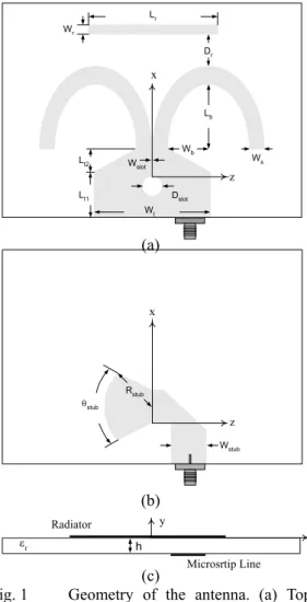
Figure 1 illustrates the geometry of the proposed antenna with the associated parameters. The antenna lies in the xz-plane with its normal direction being parallel to the y-axis. The energy is first transferred from the microstrip line to the slotline by a wideband transition. A pair of curved strips is then attached to the slotline and forms a tapered-slot feeding structure. This feeding structure acts as a wideband impedance transformer and guides the wave propagating from the slotline to the space without causing pernicious reflection. Unlike the conventional dual exponentially tapered slot antenna, in this design the outer part of the strips is curved backward to deliver part of the energy to the opposite side of the feeding aperture. An additional parasitic element is then added in front of the feeding aperture. This parasitic element alters the current distribution of the radiators and therefore has influences on both the antenna input impedance and radiation patterns. The proposed antenna was designed on a Rogers RT/Duroid 5880 substrate with h = 1.57 mm and εr = 2.2. The design parameters are
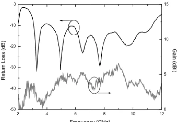
summarized in the caption of Fig. 1. The dimension of this antenna is 71 by 86 mm2. Figure 2 illustrates the measured return loss of the antenna. Referring to the figure, the operating bandwidth with |S11| < -9.5 dB (or
VSWR < 2) covers almost the whole UWB spectrum from 3.1 to 10.6 GHz. The radiation patterns were then measured, and the typical
measurement results at 3, 5, 7 and 9 GHz in both
E- (xz-) and H- (xy-) planes are illustrated in
Figs. 3 (a) and (b), respectively. The antenna gain, which is depicted in Fig. 2, is 1.5 dBi at 3 GHz, and rises to as high as 6 dBi at 9 GHz.
In addition to the radiation patterns measured at specific frequencies, we define the uniformity to quantitatively describe the performance of the radiation patterns over the entire band as
(1) where |S21,AUT(θ,φ)| is the measured radiation
pattern of the AUT at a specific plane cut and frequency, and (θmax,φmax) is the direction where maximum radiation occurs. The uniformity of the proposed antenna in E- and
H-planes are evaluated using (1) and illustrated
in Fig. 4.
(a)
(b)
(c)
Fig. 1 Geometry of the antenna. (a) Top layer (b) bottom layer and (c) cross-sectional view. The design parameters are with Lb = 25mm,
Wb = 15mm, Ws = Wr = 4mm, Lr = 38.5mm, Dr =
12mm, Wslot = 0.3mm, Dslot = 4mm, Wstub =
4.95mm, Rstub = 8mm, θstub = 100o, Wt = 22mm, Lt1 = 12mm and Lt2 = 7mm. ), )( dB 6 ) ( | ) , ( | ) ( | ) max , max ( | ( ) ( Uniformity , 21 , 21 f dB S dB S P f AUT AUT ≤ − = φ θ φ θ Lb Dr Wb Dslot Wslot z x Wt Ws Lt1 Lt2 Lr Wr Rstub Wstub z x θstub
Fig. 2 Measured return loss and gain of the proposed antenna.
(a)
(b)
Fig. 3 Measured radiation patterns of the proposed antenna (a) E-plane and (b) H-plane.
Fig. 4 Uniformity of the proposed antenna.
III. System Transfer Functions and Transient Response
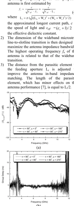
In designing UWB antennas, it is insufficient to evaluate the antenna performance solely in traditional well-defined parameters like return loss, radiation patterns and gain, etc. Instead, as indicated in [2], it is crucial to evaluate the system transfer functions as the transmitting and receiving antennas are viewed as a whole system. For UWB applications, the magnitude of this system transfer function should be as flat as possible in the operating band, and. the group delay is required to be constant over the entire band as well. A transmitting-receiving system whose transfer functions satisfy these requirements will introduce limited distortions to the baseband signals. In this project, the standard antenna pattern measurement technique is improved to evaluate the system transfer functions. The magnitudes of the measured system transfer functions at φ =0°, 90°, 180°, 270° and
θ
=90° are illustrated in Fig. 5 (a), and the corresponding group delays are depicted in Fig. 5 (b).To illustrate how the pulses are distorted by such a transmitting-receiving system, in this project a simulated baseband pulse whose spectrum completely complies with the FCC indoor emission mask is adopted to evaluate the transient waveforms. The excited pulse at the transmitting antenna terminal is assumed to be the fifth derivative of a Gaussian function,
(2) where 2 ( )2 0( ) au T t e A t g = −π . To evaluate the required transient responses, the spectrum of the simulated pulse is multiplied by the measured system transfer functions and an inverse Fourier transform is performed. The transient waveform at the receiving antenna terminal can be therefore achieved by
{
( ) ( , , ) ( )}
) , , ( 21, 1 S f S f f t sr =ℑ i ⋅ AUT ⋅∏ − θ φ φ θ , (3)where S21,AUT (f,θ,φ) is the measured system transfer function and ∏( f ) is an ideal bandpass filter from 1 to 15GHz.Figures 6 then illustrate the received waveforms evaluated using (3). Referring to the figure, it can be observed that the proposed antenna is capable of transmitting and receiving clean pulses, and is suitable for various UWB applications.
IV. Design Guideline
After performing a series of parameter study of the proposed antenna, the following design guideline is concluded.
1) In designing the antenna, the lowest
2 4 6 8 10 12 -50 -40 -30 -20 -10 0 Frequency (GHz) R e tu rn L o ss ( d B) 0 5 10 15 Ga in ( d Bi) -40 -20 0 0 30 60 90 120 150 180 -150 -120 -90 -60 -30 -40 co-pol. @ 3GHz co-pol. @ 5GHz co-pol. @ 7GHz co-pol. @ 9GHz x-pol. @ 7GHz z x θ -40 -20 0 0 30 60 90 120 150 180 210 240 270 300 330 -40 co-pol. @ 3GHz co-pol. @ 5GHz co-pol. @ 7GHz co-pol. @ 9GHz x-pol. @ 7GHz x y φ 2 4 6 8 10 12 0.0 0.2 0.4 0.6 0.8 1.0 Uni for m ity Frequency (GHz) H - plane E - plane ) ( ) ( 55g0 t dt d t si =
operating frequency fl of the proposed
antenna is first estimated by
(4) where L ( ((L W) (W W)2)/2) s b 2 s b+ + + =π l is
the approximated longest current path, c is the speed of light and εeff =(εr +1)/2 is
the effective dielectric constant.
2) The dimension of the wideband microstrip line-to-slotline transition is then designed to maximize the antenna impedance bandwidth. The highest operating frequency fu of the
antenna is related to that of the wideband transition.
3) The distance from the parasitic element to the feeding aperture Lr is adjusted to
improve the antenna in-band impedance matching. The length of the parasitic element, which has minor effects on the antenna performance [7], is equal to Ll/2.
(a)
(b)
Fig.5 (a) Magnitudes of the measured system transfer functions and (b) group delays of the proposed antenna at φ = 0o, 90o, 180o, 270o and θ
= 90o.
V. Conclusions
In this project, a novel ultra-wideband printed dipole antenna with tapered slot feed has been proposed and demonstrated. The performance of this new antenna is experimentally investigated with the help of the well-defined antenna parameters as well as the transfer functions of a
transmitting-receiving system. The evaluated transient waveforms reveal that this novel antenna is capable of transmitting and receiving clean pulses, and hence suitable for UWB applications.
Fig. 6 Transient waveforms evaluated at the receiving antenna terminal at φ = 0o, 90o, 180o,
270o and θ = 90o. Reference
[1] G. R. Aiello and G. D. Rogerson, “Ultra-wideband wireless systems,” IEEE
Microwave, vol. 4, pp. 36-47, June 2003..
[2] Z. N. Chen, X. H. Wu, N. Yang and M. Y. W. Chia, “Considerations for source pulses and antennas in UWB radio systems,” IEEE
Trans. Antennas Propagat., vol. 52, pp.
1739-1748, July 2004
[3] ——, “UWB magnetic antennas,” in 2003
IEEE AP-S Int. Symp. Dig., vol. 3, pp.
604–607.
[4] M. J. Ammann, “Improved pattern stability for monopole antennas with ultrawideband impedance characteristics,” in 2003 IEEE
AP-S Int. Symp. Dig., vol. 1, , pp. 818–821.
[5] T. G. Ma and S. K. Jeng, “A novel compact ultra-wideband printed dipole antenna with tapered slot feed,” in 2003 IEEE AP-S Int.
Symp. Dig., vol. 3, pp. 608–611.
[6] ——, “A parameter study of a novel ultra-wideband printed dipole antenna with tapered slot feed,” in Proc. Asia-Pacific
Microwave Conference, vol. 3, Nov. 2003,
pp. 1981-1984. l eff l eff l c c f L ⋅ ≈ ⋅ = ε λ ε 2 4 6 8 10 12 -120 -90 -60 -30 | S 21, AU T ( f ) | ( d B) Frequency (GHz) θ = 90o, φ = 0o θ = 90o, φ = 180o θ = 90o, φ = 90o θ = 90o, φ = 270o 2 4 6 8 10 12 0 5 10 15 20 G roup Dela y (n s) Frequency (GHz) θ = 90o, φ = 0o θ = 90o, φ = 180o θ = 90o, φ = 90o θ = 90o, φ = 270o 0 2 4 6 8 10 -0.1 0.0 0.1 θ = 90o, φ = 270o Sr (t ) (mV /m) Time (ns) 0 2 4 6 8 10 -0.1 0.0 0.1 θ = 90o, φ = 180o Sr (t) (mV /m) Time (ns) 0 2 4 6 8 10 -0.1 0.0 0.1 θ = 90o, φ = 90o Sr (t ) (mV /m) Time (ns) 0 2 4 6 8 10 -0.1 0.0 0.1 θ = 90o, φ = 0o Sr (t ) (m V /m ) Time (ns)