The 47th IEEE International Midwest Symposium on Circuits and Systems
A Generalized Methodology for Low-Error and Area-Time Efficient Fixed-
Width Booth Multipliers
Min-An Song, Lan-Da Van*, Ting-Chun Huang, and Sy-Yen Kuo
Department of Electrical Engineering, National Taiwan University, Taipei, Taiwan, R . 0 . C *National Chip Implementation Center (CIC), National Applied Research Laboratories, Taiwan, R.O.C.E-mail:
svX;uo(~~cc.ce.ntu.edu.tM.
a n dlilvan:ic?,cic.ora.t
Abstract
In this paper, we extend our generalized methodology for designing a lower-error and area-time efficient 2's-complement fixed-width Booth multiplier that receives two n-bit numbers and produces an n-bit product. The generalized methodology involving three steps results in several better error-compensation biases. These better error-compensation biases can be mapped to low-error fixed-width Booth multipliers suitable for VLSI
implementation. Finally, we successfully apply the proposed fixed-width Booth multipliers to speech signal processing. The simulation results show that the performance is superior to that using the direct-truncation fixed-width Booth multiplier.
1. Introduction
In many digital signal processing (DSP) applications such as digital filters [ l , 21 and wavelet transform, it is desirable to maintain fixed-width output word through the arithmetic operations. The Baugh-Wooley based fixed-width multipliers [ 1-
51 have been widely studied. King and Swartzlander [3] analyzed an adaptive error-compensation bias and proposed an n-bit fixed- width multiplier. In [ l , 21, we generalized this kind of Baugh- Wooley based fixed-width multipliers by properly choosing the generalized index and binary thresholding. The above scheme is based on keeping n+w colums of the subproduct array, where w is a nonnegative integer between 0 and n-I. Thus, several lower- error and area-efficient fixed-width multipliers can be obtained. However, the area-time efficient fixed-width multiplier cannot be fully achieved by the Bauth-Wooley based fixed-width multipliers. Therefore, the fixed-width Booth algorithm is currently one of the research topics.
The modified Booth algorithm proposed by the MacSorley [6] in which a triplet of bits is scanned at a time. I t is known that the recoding technique of the modified Booth algorithm has two main advantages. One is that almost half the partial products compared to the Baugh-Wooley multiplier can be saved. Hence, the number of rows of the subproduct array can be reduced by 2. The other is that, based on the first advantage, the critical delay time can be shorter than that of the Baugh-Wooley multiplier. Area saving of a fixed-width Booth multiplier can be achieved by directly truncating n least significant product bits and preserving n most significant product bits. With this method, significant truncation errors would be introduced since no error compensation is considered. In this paper, we are motivated to propose a systematic design methodology for low-error area-time efficient Booth multipliers. The methodology includes the following steps in order: 1) Propose an error-compensation bias with a new binary thresholding for a fixed value of w ; 2) simulate the value of K and error performance of the proposed error- compensation bias using our generalized index, and then select
the best index having lower error and satisfying the same value
of K for small width n; 3) construct a low-error Booth multiplier structure. Based on our methodology, while w = l , the proposed fixed-width Booth multiplier also operates lower error than those in [7] at the expense of slightly increased area-ratio with respect to each value of w. The organization of this paper is as follows. The modified Booth algorithm is concisely reviewed in Section 2. In Section 3, we propose a better error-compensation bias and present the simulation results for small width n . The improved error-compensation bias can be mapped to a new structure with respect to each value of w. The performance of the proposed is described in Section 4. Finally, brief statements in section 5 conclude the presentation.
2. Modified Booth Multiplier
Considering the multiplication of two 2's-complement integers with n-bit multiplicand A and n-bit multiplier B as
2n-1
P = A B = C P , 2 ' (1)
i=O
n-2 n-2
where A = -an.12n-'
+
C a j 2 ' , B = -bn-,2"-'+
c b j 2 j , andPi denotes the i-th output product bit. Note that ai and
b,
indicate data bits of multiplicand and multiplier, respectively. Assume n is even and the n-bit multiplier B can be rewritten asi=O j = O
( n - 2 ) / 2
B = C ( b , ; - , +b2; -2b2;+')22; , (2)
i = O
where b-, = 0 . Note that the terms in the bracket in Eq. (2) have values of {-2,
-
1, 0, I , 2). Each recoded value performs a certain operation on the multiplicand A, and then the multiple additions at each stage would be required in order to generate the correct partial product. It is worth mentioning that the operation of - A can be realized by the inversion of the multiplicand and addition of '1' at the least significant bit. Substituting Eq. (2) into Eq. (I),we can obtain Eq. (3) as
where Si =(bZiTI
+
b2; -2b2j+l)A22i, and it is known that the scanning of triplets begins from b-, to the MSB with one-bit overlapping.0-7803-8346-X/04/$20.00 02004 IEEE
So as to simplify the representation of the bit-product of each row for the Booth algorithm, we define the following notation
S I = 22r+n-1 + 5'i.n-2 22i+n-2
+
... + S l p 2 2 i,
(4)where S I , , represents the bit product of the i-th row. According to the sign-generate sign extension scheme [8], for an 8 by 8
multiplier, the sign of the final result can be expressed as
s
= (s0,7z2' )2O +(s1.7c2') 22 + I5 13 ') 24 + ( S 3 , , i Z ' )z6
~ = 8 ~ = 8 ~ = 8 ~ = 8 = (29 + g 2 7 + ( 2 1 1 + G 2 1 0 ) + ( 2 1 3 +S2,72l2)+
(215+
S3,72I4)
+
2 8 ,
(5)where S is the final result sign. From Eq. (5), the partial products of the Booth algorithm only need to add two elements
( I ,
G )
for each row and add an extra ' I ' in the 28 -weight position as shown in Fig. 1, where main and remain represent main part and remain part of the least significant bit (LSB), respectively. Thus, the sign-generate sign extension scheme can reduce many redundant full adders compared to the conventional sign extension method.1 1
Fig. 1. Modified Booth partial-product diagram with sign- generate sign extension scheme for an 8x8 multiplier.
The architecture of the Booth Multiplier as shown in Fig. 2 consists of Booth encoders, selectors (sel), full adders (FA) and half adders (HA). The Booth encoder generates Ctd,[O : 21
signals to control the selector to choose -2A, -A, 0, 1 A or 2A.
Fig. 2. An 8 X 8 modified Booth multiplier using sign-generate sign extension scheme.
3.
Design
of
Fixed-Width Booth Multiplier
The
2n
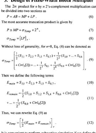
product for n by n 2's-complement multiplication can be divided into two sections asP = AB = MP+ LP
.
(6)The most accurate truncation product is given by P E MP
+
oremp
x 2",n r e m p = [ ~ p l r .
(7)
(8)
Without loss of generality, for n=8, Eq. (8) can be denoted as I 2
]
. (9)7tS3,l
+ s2.3 + sl,5 + s0.7 ) + y ( s 3 , 0 + '" + s0,6 1 1 + C W ~ ~ [ ~ ] ) + . . . + ~ S ~ , , +,(So,, + C t r l o [ 2 ] ) 2 2 r (10)I
OTemp =Then we define the following terms
= s3,1 + s 2 . 3 + s1,5 + s0,7 3 1 Eremam =
7
(S3,O + s2.2 + sl,4 + s0,6 + ctrz3L21)
(1 1) 1+
...
+
-(So,o+
Ctrlo[2]) 27Thus, we can rewrite Eq. (9) as
oTemp =
[:
- ( E m o m + E r e m a m ) . (12)l r
It is convenient to perfom exhaustive simulation if we define the generalized index. Here the generalized index for 8 by 8 multipliers is defined as
6)r~=~,r(q3'921ql,qO)=<s~,I
-,,,
>"
+ < s 2 . 3 - , , >92+<s,,-,,
>y*+
<
s0.7-%(1 3)
where the binary parameters
q3-,+,
q 2 - w ,...,
qo
E (0,I } ,
and the operatorin which is the complement of binary T
.
Furthermore,B
~
~
~
~
isreferredtoasas~
~
.
,where~
~
~
~
,
~
~
,
~
~
~
~
~
)
Q = q j ~ 2 3 + q Z ~ 2 2 + q l ~ 2 ' + q o ~ 2 0 . (15)
For example, the value of g has a range from
0 to15 for w=O
and 1. Note that if the value of the second index of Si,j in Eq.( 1 3) is less than zero, the
Si,
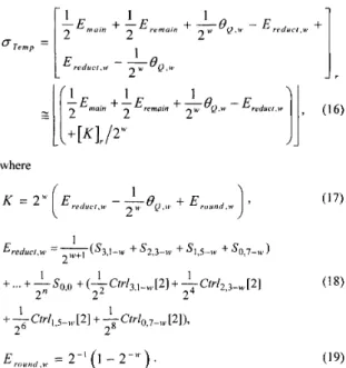
can be neglected. In [4,5], they show that lower truncation error can be obtained if larger n+w columns are kept in hardware. However, more area cost could be increased. Since the reduction and rounding errors do not own the same weight position, we adopt S-Ss' method [ 8 ] to concurrently treat reduction and rounding error. By applying Eqs.( 1 3) to ( I 5) into Eq. (12), we get
Herein, the second index of the control signal in Eq. (1 8) denotes whether the control signal exists. In case the value of the second index is less than zero, the control signal can be neglected. Note that the least significant weight of K must be limited to the n+w weight position. Concurrently treating method for reduction and rounding errors of Eq. (16). In the first step, to design a realizable error-compensation bias, two types of binary thresholding for the error-compensation bias can be change to
Type 1:
Type 2:
w = l . The restriction of the value of K can be modified as
[ K ,
I,
E{
o,
2 - 1}
for i=l,2,3 and 4. For w = I , sinceusing the same simulation procedures as mentioned in [I], we only introduce the analysis for
w
= 1 and construct the structure. In Type 1 binary thresholding, by exhaustive search we can find that one good index, shown in Fig. 3(a). We observe that the specific index, 6)Q=o,u,=I achieves better error performance where the chosen index satisfies[&Ir
= 1 and[&I,
=o,
we simulate average error as shown in Fig. 3(b). On the other hand, for Type 2 binary thresholding, the error simulation in terms of average errors are large than what find error resulted from the best index- 1 -
in
Type 1 thresholding, so we ignore the discussion in Type 2. So far, the second step is achieved. Hence, a new lower error fixed-width Booth multiplier under w=l can be described and simplified as:where B,=,,,.=, =
s3,0
+ s,,z
+
+
so.6
. In the third step, Eq. (22) can be mapped to a new structure as shown in Fig. 4.From simulation results,
ew..H-,
in Type 1 binary thresholding is still the best index for w = l . Note that the error-compensation circuit only needs three basic element gates....
3 . I....,.
\ \ J J J +Q
Fig. 3. (a) Values of KI and K2 versus different Q of the binary thresholding. (b) Average errors by exhaustive search simulation versus different Q of the binary threshoding for n = 8 .
I
1
I
I
I
I
I
I
I
I
I
_IFig. 4. Proposed low-error fixed-width 8 X 8 Booth multiplier with @,,,,,,=, .
4. Performance and Application Discussion
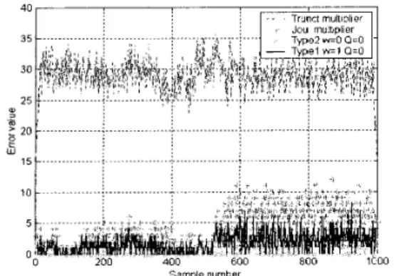
In this section, we first simulate error performance in terms of maximum error, average error, and variance of error as listed in Table 1 between the direct-truncation multiplier and the proposed fixed-width Booth multiplier. It is clearly seen that thenew structure can achieve better error performance than the direct-truncation Booth multiplier. Regarding the number of gates and the critical path delay time issues as listed in Table 2, comparison results show that the new Booth multiplier saves much area cost with respect to the full-precision Booth multiplier based on the sign-generate sign extension scheme. Most importantly, the gate count and critical delay time of the proposed structure are close to those of the direct truncation multiplier, respectively. Thus, the proposed fixed-width Booth multiplier has the area-time efficient feature with better error performance. On the other hand, we apply the proposed fixed- width multiplier to the 35-tap FIR filter for speech processing [9]. For convenience of comparison of various fixed-width multipliers, we take 1000 samples for the consonant part and vowel part of “Chicken” .We are concerned with whether the filtered waveform is accurate via our proposed fixed-width Booth multiplier, so the correct standard output is required. We use error-free output as a standard, which is used to compare the accuracy performances of fixed-width Booth multipliers. From comparison results obtain with four fixed-width Booth multipliers as show in Fig. 5 for speech processing application, we observed that Type 1 multiplier with ~ Q , o , w , , shows better
performance in the consonant and vowel parts.
Multiplier Width Maximu Average m Error Error Direct- 4 32 10.88 Truncation 6 192 70.50 z 20 ... :
;
... : ... : ... ... w Variance of Error 67.20 1465.86 i ... .i ... : ... :. ... ; ... Type 2 with Type 1 with Q=O, w=O Q=O, w = 1 SamDle numberFig. 5. Comparison results of error signals obtain with four kind of fixed-width multipliers.
5. Conclusions
This paper develops a new methodology for designing two low-error and area-time efficient fixed-width Booth multipliers. By properly choosing binary thresholding and the generalized index, we can derive several better error-compensation biases to
improve the truncation error. Furthermore, these error- compensation biases can be easily constructed as lower-error fixed-width Booth multipliers. It is very suitable for VLSI digital signal processing applications where the accuracy, area, and speed issues are crucial. Finally, we successfully apply the proposed fixed-width multiplier to a digital FIR filter for speech processing application.
6.
References
[ l ] L. D. Van, S. S. Wang, and W. S. Feng, “Design of the lower-error fixed-width multiplier and its application”,
IEEE Trans. Circuits Syst. 11, vol. 47, pp. 1 I 12-1 118, Oct. 2000.
16 4 20 IOTFA + THA
20 4 24 1 I T F A + T”,
[2] L.
D.
Van and S. H. Lee, “A generalized methodology for lower-error area-efficient fixed-width multipliers,” in Proc. IEEE Int. Symp. Circuits Syst., May 2002, vol. 1, pp. 65-68, Phoenix, Arizona.[3] E. E. Swartzlander, Jr., “Truncated multiplication with approximate rounding,” in Proc. 33rd Asilomar Conference
on Signals, Systems, and Computers, 1999, vol. 2, pp. 1480-
1483.
[4] Y. P. Lim, “Single-precision multiplier with reduced circuit complexity for signal processing applications”, IEEE Tran.
Comput. vol.41, no. 10,pp. 1333-1336,Oct. 1992.
[ 5 ] M. J. Schulte and E.E. Swartzlander, Jr. “Truncated multiplication with correction constant”, VLSI Signal Processing, VINew York: IEEE Press, 1993, pp. 338-396.
[6] 0. L. MacSorley, “High-speed arithmetic in binary computer”, Proc. IRE, vol. 49, pp. 67-9 1, 196 1.
[7] S. J. Jou and H. H. Wang, “Fixed-width multiplier for DSP application,” IEEE Int. Con$ Computer Design, Sep. 2000,
[8]
E. de Angel and E. E. Swartzlander, Jr., “Low power parallel multipliers,’’ IEEE VLSI Signal Processing IX, 1996,[9]
M. E. Paul, and K. Bruce, C Languuge Algorithms for Digital Signal Processing. Englewood Cliffs, NJ: Prentice-Hall, 199 1.
pp. 318-322.
pp. 199-208.
Table 1 : Comparison Results of Three Kinds of Errors among
with 6 1 41
I
12.25I
175.88Q=O, w=l 8
-
I
798 -,-
I
7 9 6 9 ._.-_
I
7514 AA .- -
. . . . 16I
394248I
42533.53 1186761423 Table 2: Comparison Results of Area and Critical Delay Timeamong Different Booth Multipliers for n = 8 Multiplier
Time
13TF.4 + 3THA
Direct-Truncation