System Analysis of VLSI Architecture for 5/3 and 1/3
Motion-Compensated Temporal Filtering
Ching-Yeh Chen, Chao-Tsung Huang, Yi-Hau Chen, Shoa-Yi Chien, and Liang-Gee Chen, Fellow, IEEE
Abstract—Motion-compensated temporal filtering (MCTF) is an
innovative prediction scheme for video coding and it has become the core technology of the coming video coding standard, Scalable Video Coding. Since MCTF is important, this paper provides the system analysis of MCTF for hardware architecture design, in-cluding computational complexity, external memory bandwidth, and external memory size. The one-level MCTF is analyzed first, in which several frame-level data reuse schemes are proposed and the tradeoffs between external memory usages and on-chip memory size in these frame-level data reuse schemes are also discussed. Next, the analysis is extended to multilevel MCTF. The computa-tional complexity of multilevel MCTF is close to that of tradicomputa-tional MC prediction with two reference frames. The memory bandwidth of multilevel MCTF depends on the frame-level data reuse scheme and performing the update stage or not. The external memory size is linearly proportional to the number of decomposition levels. Fi-nally, a real-life test case is given to compare the system require-ments between MCTF with various frame-level data reuse schemes and the prediction scheme of H.264/AVC.
Index Terms—Motion-compensated temporal filtering (MCTF),
scalable video coding, video coding, VLSI architecture.
I. INTRODUCTION
E
XISTING hybrid video standards, such as MPEG series [2]–[4] and the emerging H.264/AVC [5], mainly con-sist of a close-loop motion-compensated prediction (MCP) scheme and a transform-based texture coder. The “close-loop” means it uses the reconstructed previous frames to predict the current frame, which forms a feedback loop. The close-loop MCP scheme has been highly optimized for the compression efficiency in the last decade, and H.264/AVC is a landmark of this development. However, for many video applications in the present and the future, the spatial, temporal, and signal-to-noise-ratio (SNR) scalabilities become more and more demanded. The scalability means we can have multiple adap-tations in one video bitstream, such as different frame sizes, frame rates, and visual qualities. However, the close-loop MCP scheme is hard to provide these scalabilities while maintaining Manuscript received May 23, 2005; revised December 1, 2005. This work is an extension, in part, of [1], which was published by the International Confer-ence on Acoustic, Speech, and Signal Processing 2005, and its journal version is invited to be submitted to one of the Signal Processing Society’s publications by the IEEE Signal Processing Society. The associate editor coordinating the review of this manuscript and approving it for publication was Prof. Brian L. Evans.The authors are with DSP/IC Design Lab, Graduate Institute of Electronics Engineering and Department of Electrical Engineering, National Taiwan University, Taipei, Taiwan, R.O.C. 106 (e-mail: [email protected]; [email protected]; [email protected]; [email protected]. ntu.edu.tw; [email protected]).
Digital Object Identifier 10.1109/TSP.2006.880202
a high compression efficiency due to the drift problem, which is the mismatch of the reconstructed frame between the encoder and decoder. In order to avoid the drift problem, the com-pression efficiency will be degraded very much and become unacceptable when there are many scalability layers.
The open-loop interframe wavelet coding scheme becomes a good alternative for scalable video coding, which concept is to perform a wavelet transform in the temporal direction. But the coding performance is unacceptable without motion compensation (MC). In 1993, Ohm introduces a block-based displacement interframe scheme using the Haar filter [6]. How-ever, the compression efficiency is still not comparable to the existing MCP video standards, until the lifting-based wavelet interframe scheme is proposed and the longer tap wavelet filters, like 5/3 filter, are used [7], [8]. For more details, please refer to [9] and [10].
MPEG has identified a set of applications that require scal-able and reliscal-able video coding technologies. After evaluating the response to Call for Proposals on Scalable Video Coding (SVC) [11], it has been shown that there is a new and innovative video technology that MPEG can bring to industry in a future video standard [12]. In the two most significant proposals [13], [14] and many other proposals, the lifting-based motion-com-pensated temporal filtering (MCTF) is the core technology to provide scalabilities in video coding. The MCTF not only can provide a variety of efficient scalabilities because of no drift problems in the open-loop structure but also can increase the compression efficiency of H.264/AVC [14].
Since MCTF is a breakthrough and the key component of the interframe wavelet video coding and the coming video coding standard, SVC [15], we would like to present the first work on VLSI architecture of MCTF by analyzing system and memory issues in this paper. First, we analyze the frame-level data reuse schemes for one-level MCTF. And based on the analysis of one-level MCTF, the system issues of multilevel MCTF are dis-cussed. Some important factors of multilevel MCTF are intro-duced first and followed by the analysis of computational com-plexity, external memory bandwidth, external memory storage, and coding delay. Last of all, a real-life test case is given to compare the system requirements between MCTF with various frame-level data reuse schemes and the prediction scheme of H.264/AVC. This paper is organized as follows. In Section II, the operation of MCTF will be introduced, and next the analysis of one-level MCTF is discussed in Section III. In Section IV, we extend the analysis from one-level to multilevel MCTF, and a case study is given for the comparison. Finally, we conclude the analyses in Section V.
Fig. 1. The operations of MCTF and SVM. (a) One-level 5/3 MCTF scheme, where the light gray frames (H) are the H-frames, and the heavy gray frames (L) are the L-frames. (b) Two-level MCTF that applies one-level MCTF on L-frames, recursively. (c) Coding scheme of SVM.
II. MOTION-COMPENSATEDTEMPORALFILTERING MCTF is to perform a wavelet transform in the temporal di-rection with MC. The coding performance and coding delay de-pend on which wavelet filter is adopted. From recent experi-mental results [9], [16], MCTF is usually implemented by use of 5/3, 1/3, or Haar filter with the lifting scheme, which is an efficient implementation method of wavelet filters and guaran-tees the perfect reconstruction property. For simplicity, MCTF represents the lifting-based MCTF using the 5/3 or 1/3 filter in the following.
The 5/3 MCTF can be simply illustrated by Fig. 1(a), where only two lifting stages are involved. The prediction stage uses even frames to predict odd frames, and the generated residual frames are the high-pass frames (H-frames), which can also be viewed as B-frames predicted by neighboring frames. The up-date stage uses the H-frames to upup-date the even frames, and then the updated frames are the lowpass frames (L-frames). The up-date weighting factor is 1/4 for the 5/3 filter. The 1/3 MCTF is just to skip the update stage of 5/3 MCTF and treat the even
Fig. 2. The assumed architecture of MCTF.
frames as the L-frames. The open-loop MCTF means the frames used to predict or update are the original or filtered frames, in-stead of the reconstructed or coded frames in the close-loop MCP scheme.
For aligning the objects in different frames, the two lifting stages require motion vectors, but motion estimation (ME) is only performed in the prediction stage to find the best motion
vectors, and . As for the update motion
vec-tors, and , they are derived from and
for saving the motion vector cost. Fig. 1(a) only shows the operations of one-level MCTF, and multilevel MCTF can be derived by recursively performing the operations of one-level MCTF on the L-frames, as shown in Fig. 1(b).
Fig. 1(c) shows the basic coding scheme of SVM [17]–[19], which consists of MCTF, Texture Coding, and I or IPPP Coding. After the decomposition of MCTF, H-frames are directly coded by Texture Coding, and L-frames are further processed by I or
IPPP Coding. Texture Coding is a traditional transform-based
texture coder, which includes discrete cosine transform, quan-tization and entropy coding. I or IPPP Coding is a close-loop intra- or intercoder, such as H.264 I-frame or IPPP scheme. In
MCTF of SVM3.0, the motion vectors in the prediction stage,
and , can be refined in a biiterative way, which performs the integer ME of the left and right branches in Fig. 1(a) separately and refines the fractional-pixel ME jointly. And to perform update operations or not is evaluated by use of the residual energy and the overlapped area of the derived reference block and motion vector.
Multilevel 5/3 and 1/3 MCTF are performed in a bottom-to-top order that is from higher to lower frame rates, as shown in Fig. 1(b). In SVC WD1.0 [15], a coding scheme called Hierarchical B-frames (HB) is introduced to provide an H.264/AVC compatible scalable coding bitstream. HB is to perform multilevel MCTF in a top-to-bottom way that is from lower to higher frame rates to be compatible with the generic B-frames of H.264/AVC. The top-to-bottom decomposition is possible only when all update steps are ignored, so the coding performance of open-loop HB is very similar with that of 1/3 MCTF.
III. ONE-LEVEL MOTION COMPENSATED TEMPORALFILTERING
In this section, we will analyze one-level MCTF. The opera-tions of MCTF are dominated by ME and MC, so we assume a general architecture of MCTF would be like that of ME. Fig. 2 shows the assumed architecture, in which Processing Engine is
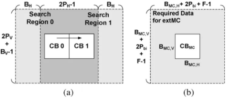
Fig. 3. The required data of ME and MC. (a) The required data for ME with level C scheme, where the heavy gray region is the overlapped and reused re-gion. (b) The required data for extMC with biiterative refinement. (P = 0 if biiterative refinement is not performed.)
responsible for all operations of MCTF, On-Chip Memory is used to store the required searching range data for data reuse, and the required reference or current data are stored and loaded from External Memory. In the following subsections, because MCTF is an open-loop video coding, it is possible to reuse the searching range data between two current frames. There-fore, several frame-level data reuse schemes are proposed and the tradeoff between the required external memory bandwidth, on-chip memory size, and external memory storage will also be discussed.
A. Redundancy Access for ME and MC in MCTF
ME and MC dominate the required memory bandwidth of MCTF. The required memory bandwidth of reference frames and on-chip memory size in ME depend on ME algorithms, architectures, and searching range data reuse schemes. In order to simplify the analysis and generalize our analyzed results, the concept of redundancy access factor, (pixels/pixel), which is used to represent the memory bandwidth of one refer-ence frame [20], [21] is adopted. The redundancy access factor is defined as Total memory bandwidth for reference
frame/Minimum memory bandwidth (pixel count in total), which
means that the required memory bandwidth is times of the minimum memory bandwidth. In another viewpoint, can be interpreted as that if one current pixel is computed, reference pixels are required to be loaded from external memory.
In [20], [21], there are four searching region data reuse schemes from Level A to Level D, in which Level C scheme is the most common used in previous works. Therefore, we take Level C scheme as an example to illustrate the computation of the redundancy access factor. Level C scheme can reuse the overlapped searching region between two successive cur-rent blocks in the horizontal direction, as shown in Fig. 3(a),
where the searching range is and in
the horizontal and vertical directions, and and are the width and height of the current block, respectively. So the
is
(1) MC in MCTF may require redundant memory access for fractional-pixel MC or biiterative motion vector refinement in
TABLE I
TYPICALVALUES OFRa ANDRa WITHBIITERATIVE
REFINEMENT,[0P ; P ),FORSVC WD1.0
SVM3.0. We classify MC into two categories, internal MC (intMC) and external MC (extMC). The former performs MC internally without external memory access because there are sufficient data in the searching region buffer for fractional-pixel MC. The latter performs MC by loading data from external memory. If the motion vector is fractional-pixel, more data than one block are required to be loaded from external memory for the interpolation of extMC. Moreover, if the biiterative refine-ment is required, the searching region data for the biiterative refinement should also be read from external memory.
For extMC without biiterative refinement, the required data from external memory can be formulated as
(2)
where and are the width and height of the block
to be performed MC (MC block), and is the interpolation filter length. The corresponding redundancy access factor
can be defined by
(3) If considering the biiterative refinement, the required data be-comes
(4) as shown in Fig. 3(b), where the excess searching region for the biiterative refinement is . The corresponding
redun-dancy access factor can be written as
(5) In SVC WD1.0, because variable block size ME is adopted, we discuss several typical values of and
for MC blocks with different block sizes in Table I. Based on Table I, the bandwidth overhead of extMC for small MC blocks is quite large, and the biiterative refinement makes the overhead larger.
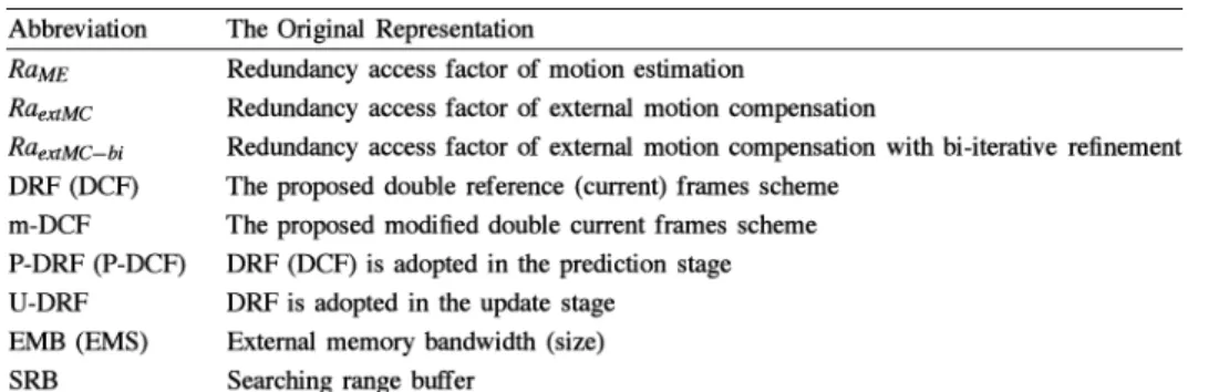
By use of redundancy access factors, the required memory bandwidth of ME and MC can be easily compared and cal-culated even if different ME algorithms, architectures, or data reuse schemes are adopted. Finally, the abbreviations in the fol-lowing subsections are summarized in Table II, first.
TABLE II THELIST OFABBREVIATIONS
B. Memory Analysis for Prediction Stage
The main difference between open-loop MCTF and close-loop MCP is that the reference frames in MCTF are the orig-inal frames or L-frames, and those in MCP are the reconstructed or coded frames. Hence, in MCTF, the ME of different frames can be performed simultaneously. Moreover, there are two refer-ence frames in the prediction stage of MCTF, so we assume that the on-chip memory size will not be larger than two searching range buffers. Based on this assumption, the possible frame-level data reuse schemes are proposed and their tradeoffs be-tween on-chip memory size and external memory bandwidth are also discussed, in the following.
1) Direct Implementation of Prediction Stage: The direct
im-plementation is to perform the left and right ME separately, as shown in Fig. 4(a). The external memory bandwidth (EMB) is
(pixels/pixel), where the divisor two exists because the pre-diction stage is performed for every two frames. The required on-chip memory is one searching region buffer (SRB), which depends on which macroblock-level data reuse scheme is used.
2) Proposed Double Reference Frames: Instead of the
di-rect implementation, we propose the double reference frames scheme (DRF) as shown in Fig. 4(b), which performs left and right ME together for one current frame. The on-chip memory size of DRF is , and its EMB is
Compared to direct implementation, DRF can save the memory access of left extMC, but its penalty is a larger on-chip memory.
3) Proposed Double Current Frames Scheme (DCF):
Be-cause of the open-loop prediction, we can reuse the searching region between two current frames. Therefore, the DCF is pro-posed and shown in Fig. 4(c) where the loaded searching region
Fig. 4. Data reuse schemes for the prediction stage. C: Current frame; R: Refer-ence frame. (a) Direct implementation (separate left and right ME). (b) The pro-posed double reference frames scheme (DRF). (c) The propro-posed DCF scheme. (d) The proposed m-DCF.
of the reference frame can be used for the ME of current frame and , simultaneously, but the MC from frame to becomes extMC. The on-chip memory size is reduced to
, and the EMB is shown in the equation at the bottom of the page. Compared to DRF, DCF can reuse the searching range and save half memory access and on-chip memory size, but the penalty is that extMC is required.
4) Proposed Modified Double Current Frames Scheme (m-DCF): Although DCF can reduce the memory access
of ME, it suffers the bandwidth overhead of extMC, which
depends on the average of all MC blocks. If
is larger than , the overhead of extMC will make DCF less efficient than DRF. Besides, the memory access of extMC is irregular and may lead to a lower efficiency of external memory access. So we propose another kind of
TABLE III
COMPARISONS OFFRAME-LEVELDATAREUSESCHEMES FOR THEPREDICTIONSTAGE OF5/3 MCTF
the frame-level data reuse scheme, the m-DCF, which can eliminate the memory bandwidth of extMC by interpolating the best matched blocks of the reference frame to be the MC frame for the current frame in advance and storing into the external memory, as shown in Fig. 4(d). Then, m-DCF not only can reduce memory access of extMC, but also can let the memory access of be regular compared to that of in DCF. The EMB of m-DCF is
and the on-chip memory size is the same as that of DCF. Note that, because MC of left ME is performed first, the number of iterations in the biiterative refinement is limited and then the coding performance of the biiterative refinement may be degraded.
5) Comparison: The four mentioned reuse schemes are
sum-marized in Table III. In terms of EMB, the direct implementation is the worst among the four schemes. As for the three proposed schemes, the performances depend on the values of and
. is the average of all MC
blocks, which is related to motion vector precision (integer-pixel or fractional-(integer-pixel) and the MC block size.
In order to illustrate this feature, we take two examples, in which Level C scheme is used. First, we assume that the
searching range is , , and the average
bandwidth of extMC with biiterative refinement
is equal to 2. Then, the ratio of the required EMB in Direct implementation, DRF, DCF, and m-DCF is 6:4:4.5:4. That is, DCF and m-DCF do not have better performances than DRF does. But when the searching range is increased to
, , and the worst case of extMC occurs
, the ratio will become 13:10:8.5:7. The reduction ratios of m-DCF are 46% and 30% of the direct implementation and DRF, respectively. That is, if the required memory bandwidth of reference frames is larger, the perfor-mances of DCF and m-DCF which can share the searching range data will be better. Besides, the performance of DCF will be seriously degraded if a large exists.
In summary, DCF requires less external memory bandwidth
than DRF does, if . On the other
hand, m-DCF requires less external memory bandwidth than DRF does if . As for on-chip memory size, DCF and m-DCF only require half of on-chip memory size in DRF. More-over, because of no extMC in DRF and m-DCF, the memory ac-cess of them is always regular. Contrarily, the memory acac-cess of direct implementation and DCF is irregular. Then, the efficiency of external memory access in DCF could be lower than that in
Fig. 5. Frame-level data reuse schemes of 5/3 MCTF. P: Prediction stage; U: Update stage. (a) P-DRF/U-DRF. (b) P-DCF/U-DRF.
DRF or m-DCF. Finally, because the direct implementation is worse than the three proposed schemes, it will be excluded from the discussion in the following.
C. The Impact of Update Stage
In the update stage, only the extMC is performed, and the motion vectors are derived from those in the prediction stage. Since ME is not performed in the update stage, DCF cannot provide advantages. The update stage of DRF is as shown in the top part of Fig. 5(a), and the EMB is
Because the MC blocks in the update stage of SVC WD1.0 are all 4 4 blocks, the required memory bandwidth of extMC is very large, as shown in Table I.
D. Memory Analysis of One-Level MCTF
The different frame-level data reuse schemes for 5/3 MCTF are shown in Fig. 5, where the abbreviation of P-DCF/U-DRF is that in the prediction stage, DCF is adopted, and in the update stage, DRF is adopted. The frames expressed by bold lines represent those need to be stored in the external memory for performing 5/3 MCTF. As shown in Fig. 5, because of the frame-level data reuse scheme, the required external memory size (EMS) of DCF is one more frame than that of DRF. And if m-DCF is used in Fig. 5(b), one more frame, , will be required to be stored in the external memory, compared to DCF. The analyzed result of one-level MCTF is listed in Table IV,
where the average bandwidth is used, and and
represent the extMC in the prediction and update stages, respectively. In a word, the update stage has large over-heads of external memory bandwidth and memory size. The former can be reduced by decreasing the average , but the latter cannot be reduced. In the prediction stage, compared
TABLE IV
SUMMARY OFMEMORYANALYSIS FORONE-LEVELMCTF
to DRF, by sharing the searching range data between two current frames, DCF can save half memory bandwidth and half on-chip memory size, but requires more external memory size for frame-level data reuse. Moreover, the performance
of DCF will be degraded due to extMC , and
this can be improved by use of m-DCF, in which the overhead is the increase of external memory size. Finally, for different
hardware systems and specifications ( , , and
), the frame-level data reuse scheme with a proper tradeoff between external memory usages and on-chip memory size can be selected, by using Table IV.
IV. ANALYSIS OFMULTI-LEVELMCTF
When extending one-level MCTF to multilevel MCTF, three preconditions should be given: decomposition level, intercoding L-frames or not, and performing update stage or not. In the fol-lowing, these preconditions are introduced, and then the system issues of multilevel MCTF are discussed.
A. The Preconditions of Multilevel MCTF
1) Decomposition Level: According to the coding results
using SVM3.0, the four-level decomposition has the best
com-pression efficiency for CIF sequences and
by use of 5/3 MCTF, as shown in Fig. 6(a) and (b), respectively. However, two- or three-level MCTF is the best se-lection for the sequence , as shown in Fig. 6(c). A higher decomposition levels does not always bring more quality be-cause of the finite searching range. It means that the number of decomposition levels should depend on the characteristics of sequences, and different decomposition levels of MCTF should be supported in the same multilevel MCTF system.
2) Intercoding for L-Frames: The second precondition is
to perform intercoding for the L-frames or not. The L-frames are the base layer in the temporal axis for multilevel MCTF coding system and they can be intracoded or intercoded using close-loop MCP schemes (IPPP), as shown in Fig. 1(c). Inter-coding can provide a better compression ratio but may suffer a worse error resilience capability. On the other hand, intracoding can provide a better scalability but has a worse visual quality. The differences of R-D curves between inter- and intracoded L-frames are shown in Fig. 6(d) and (e). The former is the
re-sult of with four-level 5/3 MCTF, where
one L-frame exists for every 16 frames, and the difference be-tween inter- and intracoded L-frames is about 1 dB. The latter shows the result of with two-level 5/3 MCTF, where one L-frame exists for every four frames, and the difference between
inter- and intracoded L-frames becomes 2–4 dB, that is a heavy penalty.
3) Update Stage: To perform update stage or not is the third
precondition. If the update stage is not performed, it can also be decided to perform 1/3 MCTF or HB. Fig. 6(f) gives an ex-ample for these different configurations by use of SVM3.0 for , where the coding result of H.264/AVC using JM9.0 [22] is also provided for comparison. The 5/3 MCTF can provide the best R-D performance. The coding efficiencies of 1/3 MCTF and HB are nearly the same under the open-loop prediction scheme. From this figure, MCTF is shown to be capable of boosting the coding performance of H.264/AVC. Especially, the H.264 Main Profile configuration uses five reference frames, while SVM3.0 only uses two refer-ence frames for the bidirectional motion estimation of MCTF and one reference frame for the intercoded L-frames.
B. Analysis of Multilevel MCTF
In the following analysis, MCTF is assumed to use the closest frame as the reference frame of each direction for the prediction stage, and the L-frames are intercoded as IPPP.. structure using previous frames as reference frames. Since the hardware re-quirements of open-loop 1/3 MCTF and HB are all exactly the same, HB will not be discussed in the following.
1) Computational Complexity and Memory Access: In
each decomposition level, the redundancy access factors, and , will be different, but for the sake of simplicity, in the following, the redundancy access factors are assumed to be the same for every decomposition level. Then the computational complexity and external memory access are exponentially decreased for higher decomposition levels. As shown in Fig. 7, the number of input frames in the second level MCTF is only half of that in the first level MCTF, and so as the workload (WL). If the workloads are assumed to be dominated by ME and MC, WL can be formulated as follows:
level
level level
(6)
where level, , and level are average
Fig. 6. R-D curves derived from SVM3.0 for three preconditions of multilevel MCTF with CIF Format and 30 fps; different level decompositions of 5/3 MCTF. (a)MobileandCalendar, SR : [016; 16). (b) Foreman, SR : [016; 16). (c) Stefan, SR : [032; 32); intercoded L-frames. (d) MobileandCalendar with four-level 5/3 MCTF,SR : [016; 16). (e) Stefan with two-level 5/3 MCTF, SR : [016; 16); update stage. (f) Comparison of SVM3.0 and JM9.0 for sequence MobileandCalendar, SR : [016; 16).
Fig. 7. Scaling effect of workload for three-level MCTF and intercoded L-frames with one reference frame.
and -level MCTF, respectively. It can be found that the compu-tational complexity of -level MCTF is very close to traditional close-loop MC prediction with two reference frames.
The EMB has a similar scaling effect as computation complexity
EMB level EMB level
Fig. 8. Signal flow graph of two-level MCTF system. (a) 5/3 MCTF. (b) 1/3 MCTF, where the solid line is P-DRF/U-DRF and the dotted line is P-DCF/U-DRF.
where EMB level is as shown in Table IV. EMB level is also close to the double of EMB level if .
2) External Memory Size: The required external memory
size (EMS) of MCTF is linearly proportional to the decomposi-tion level . For 5/3 MCTF, the external memory size is
level level (8)
where level is as shown in Table IV, which depends on the adopted data reuse scheme. For 1/3 MCTF, the frame in Fig. 4 can be shared among all MCTF levels because no update stages are performed. Thus, for 1/3 MCTF, the external memory size is
level level (frames) (9)
where level is also as shown in Table IV. The EMS of multilevel MCTF is much larger than the traditional close-loop MCP scheme, when is large.
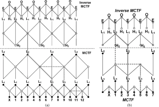
3) Coding Delay: The coding delay is an important issue
for the open-loop MCTF prediction because it is much longer than traditional MC prediction. In [23], only the encoding delay is discussed. In the following, the coding delay is considered, which is defined as the maximum distance between the decoded frame and the farthest frame that is required to encode frame . In the other words, the coding delay is the minimum timing delay between the real-time captured video and the decoded video. Fig. 8(a) and (b) shows examples of two-level 5/3 and 1/3 MCTF systems, respectively. For two-level 5/3 MCTF, the coding delay of P-DRF/U-DRF is nine frames, and that of
P-DCF/U-DRF is twelve frames. For two-level 1/3 MCTF, the coding delay of DRF is three frames, and that of DCF is five frames.
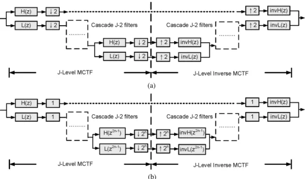
The coding delays of 5/3 MCTF and 1/3 MCTF with different schemes can be derived by using multirate filter bank equa-tions. Fig. 9(a) shows the original recursive filter-bank represen-tations of J-level MCTF and inverse MCTF (IMCTF). We can change the positions of upsample and downsample, as shown in Fig. 9(b), and then all filters of different decomposition levels which are directly cascaded can be synthesized to be one filter. Therefore, the coding delay of P-DRF/U-DRF is
(10) Similarly, the coding delay of P-DCF/U-DRF can be calculated as
(11) Note that in [23], the encoding delay of P-DRF/U-DRF is shown
to be frames. By the same method, the decoding
delay of 5/3 IMCTF can also be derived as frames. In P-DRF/U-DRF or P-DCF/U-DRF, the coding delay is equal to the sum of encoding and decoding delays, because it happens that the coding delay path is the sum of longest delay paths in 5/3 MCTF and 5/3 IMCTF. However, the coincidence does not happen to 1/3 MCTF, which can be found in Fig. 8(b). In 1/3 MCTF, the coding delay of P-DRF or P-DCF can be derived as
or frames from the signal data flow
in Fig. 8(b) or the filter-bank representation. The coding delays for different data reuse schemes are summarized in Table V.
Fig. 9. The filter-bank representation of J-level MCTF and inverse MCTF. (a) The original filter-bank representation. (b) The modified filter-bank representations.
TABLE V
CODINGDELAYS OFJ-LEVEL5/3OR1/3 MCTF WITHDIFFERENT
DATAREUSESCHEMES
In summary, the coding delays of multilevel MCTF are expo-nentially increased with . The ratio of coding delays for 5/3 MCTF with P-DRF/U-DRF, 5/3 MCTF with P-DCF/U-DRF, 1/3 MCTF with P-DRF, and 1/3 MCTF with P-DCF is about 3:4:1:1.5.
4) Summary: From the previous analysis, because of scaling
effect, the computational complexity is very similar for all kinds of configurations for multilevel MCTF, which is bounded by the computational complexity of ME with two reference frames per frame if is one. Similarly, the external memory bandwidth depends on the frame-level data reuse schemes and performing update stage or not, but it is quite similar for dif-ferent MCTF levels with the same data reuse scheme. However, the external memory storage requirement is linearly propor-tional to the MCTF decomposition level, and the coding delay is exponentially increased as the MCTF decomposition level increases.
C. Case Study
To show the real-life system requirement, based on our pre-vious analysis, a case study is given which performs four-level MCTF for D1 sequences with 30 fps. The searching range of ME is , and Level C data reuse scheme is adopted such that . Because of supporting variable block size ME, we assume the extMC is all performed on a 4 4 block such
that . And if
biiter-ative refinement is not performed for DCF in the
prediction stage. The L-frames are intercoded as IPPP.. struc-ture with one reference frame. Two configurations of H.264/ AVC, IBBPBBP and IBPBP with two reference frames, are also compared (only the MC prediction). For IBPBP configuration,
the external memory bandwidth is because of two
reference frames. As for IBBPBBP configuration, the external memory bandwidth (pixels/pixel) is calculated as
because the searching region of two B-frames can be shared. The comparisons are listed in Table VI. Compared to different frame-level data reuse schemes, m-DCF reduces the external memory access but requires the largest external storage. DRF has the smallest external memory size but requires the largest on-chip memory size and external memory bandwidth. Among various coding schemes, the required EMB of 1/3 MCTF is close to those of H.264/AVC configurations. But due to update stage, 5/3 MCTF requires nearly double of EMB of H.264/AVC. The external storage requirement of MCTF is several times of that of H.264/AVC, but the on-chip memory of MCTF is equal to or less than that of H.264/AVC.
V. CONCLUSION ANDFUTUREWORK
In this paper, we analyze system issues of MCTF to be a reference for VLSI architecture design. By using the re-dundant access factors of ME and MC, the external memory bandwidth of ME with various data reuse schemes and MC with fractional-pixel resolution and biiterative refinement is evaluated. Based on these factors, we discuss the memory issues of one-level MCTF, including external memory band-width, external memory size, and on-chip memory size, and
TABLE VI
SYSTEMREQUIREMENTCOMPARISONS OFFOUR-LEVELMCTFANDH.264/AVC WITHTWOREFERENCEFRAMES
propose three frame-level data reuse schemes for the pre-diction stage. Compared to direct implementation of MCTF, DRF can save the external memory bandwidth of extMC, and DCF can reduce the memory bandwidth and on-chip memory size by sharing the searching range data between two cur-rent frames. However, the penalty of DCF is the increase of external memory bandwidth for extMC, and m-DCF can elim-inate it with the increase of external memory size. Different frame-level data reuse schemes provide variant tradeoffs be-tween external memory size, external memory bandwidth, and on-chip memory size. Therefore, for different hardware sys-tems and specifications, the frame-level data reuse scheme with a proper tradeoff between external memory usages and on-chip memory size can be selected.
After analyzing one-level MCTF, we extend our analysis from one-level MCTF to multilevel MCTF. Three precondic-tions of multilevel MCTF, decomposition level, intercoding L-frames or not, and performing update stage or not, are discussed first, and next, many important system parameters are formulated, including computational complexity, external memory usages, and coding delay. For multilevel MCTF, the computational complexity is close to that of traditional MC prediction with two reference frames. The required memory bandwidth with or without the update stage is double of or near the same as that of traditional MC prediction with two reference frames, respectively. But the required external memory size is much more than that of traditional MC prediction with two reference frames. The coding delay is exponentially increased as the MCTF decomposition level increases.
Finally, based on our analysis, the required computational complexity and operations are very similar for MCTF, H.264 IBPBP, and H.264 IBBP, but the requirements of external memory bandwidth and size are quite variant. Therefore, it is very suitable to design one flexible hardware with rate-distor-tion-computation scalability which not only can support various coding schemes but also can fit different external requirements by adopting a suitable coding scheme. That is, given the same video quality, if more external memory bandwidth and external memory size can be used for video coding, a complicated coding scheme with a high compression ratio, such as 5/3 MCTF, can be performed in this architecture. Oppositely, if the available external memory resources are limited, this architec-ture can be configured to be a simple coding scheme, such as 1/3 MCTF, H.264 IBBP or IPPP, to guarantee that the video coding can work. Our next step is to design and implement this hardware architecture.
REFERENCES
[1] C.-T. Huang, C.-Y. Chen, Y.-H. Chen, and L.-G. Chen, “Memory anal-ysis of VLSI architecture for 5/3 and 1/3 motion-compensated temporal filtering,” in Proc. IEEE Int. Conf. Acoust., Speech, Signal Process., 2005, pp. v/93–V/96.
[2] Information Technology—Coding of Moving Pictures and Associated
Audio for Digital Storage Media at Up to About 1.5 Mbit/s—Part 2: Video, ISO/IEC 11172-2, 1993.
[3] Information Technology—Generic Coding of Moving Pictures and
As-sociated Audio Information: Video, ISO/IEC 13818-2 and ITU-T
Rec-ommendation H.262, 1996.
[4] Information Technology—Coding of Audio-Visual Objects—Part 2:
Vi-sual, ISO/IEC 14496-2, 1999.
[5] Draft ITU-T Recommendation and Final Draft International Standard
of Joint Video Specification, ITU-T Recommendation H.264 and
ISO/IEC 14496-10 AVC, Joint Video Team, 2003.
[6] J.-R. Ohm, “Advanced packet-video coding based on layered VQ and SBC techniques,” IEEE Trans. Circuits Syst. Video Technol., vol. 3, no. 3, pp. 208–221, Jun. 2002.
[7] A. Secker and D. Taubman, “Motion-compensated highly scalable video compression using an adaptive 3D wavelet transform based on lifting,” in Proc. IEEE Int. Conf. Image Process., 2001, pp. 1029–1032. [8] B. Pesquet-Popescu and V. Bottreau, “Three-dimensional lifting schemes for motion compensated video compression,” in Proc. IEEE
Int. Conf. Acoust., Speech, Signal Process., 2001, pp. 1793–1796.
[9] D. Taubman, “Successive refinement of video: fundamental issues, past efforts and new directions,” in Proc. Int. Symp. Visual Commun. Image
Process., 2003, pp. 791–805.
[10] J.-R. Ohm, “Advances in scalable video coding,” Proc. IEEE, pp. 42–56, Jan. 2005.
[11] Call for Proposals on Scalable Video Coding Technology, ISO/IEC JTC1/WG11 Doc. N5958, Oct. 2003, ISO/IEC JTC1.
[12] Scalable Video Coding and IPMP Make Big Strides, ISO/IEC JTC1/ WG11 Doc. N6303, Mar. 2004.
[13] J. Xu et al., 3D Subband Video Coding Using Barbell Lifting , ISO/IEC JTC1/WG11 Doc. M10569/S05, Mar. 2004.
[14] H. Schwarz, D. Marpe, and T. Wiegand, Scalable Extension of
H.264/AVC , ISO/IEC JTC1/WG11 Doc. M10569/S03, Mar. 2004.
[15] J. Reichel, H. Schwarz, and M. Wien, Working Draft 1.0 of 14496-10:200x/AMD1 Scalable Video Coding , ISO/IEC JTC1/SC29/WG11 and ITU-T SG16 Q.6, Doc. N6901, Jan. 2005.
[16] H. Schwarz, D. Marpe, and T. Wiegand, “MCTF and scalability exten-sion of H.264/AVC,” in Proc. Picture Coding Symp., 2004.
[17] Scalable Video Model 1.0, ISO/IEC JTC1/WG11 Doc. N6372, Mar. 2004, ISO/IEC JTC1.
[18] Scalable Video Model 2.0, ISO/IEC JTC1/WG11 Doc. N6520, Jul. 2004, ISO/IEC JTC1.
[19] Scalable Video Model 3.0, ISO/IEC JTC1/WG11 Doc. N6716, Oct. 2004, ISO/IEC JTC1.
[20] M.-Y. Hsu, “Scalable module-based architecture for MPEG-4 BMA motion estimation,” M.S. thesis, Graduate Inst. of Elec. Eng., National Taiwan Univ., Jun. 2000.
[21] J.-C. Tuan, T.-S. Chang, and C.-W. Jen, “On the data reuse and memory bandwidth analysis for full-search block-matching VLSI architecture,”
IEEE Trans. Circuits Syst. Video Technol. , vol. 12, no. 1, pp. 61–72,
Jan. 2002.
[22] Joint Video Team of ISO/IEC MPEG and ITU-T VCEG, H.264/AVC Reference Software JM9.0 2004.
[23] G. Pau, B. Pesquet-Popescu, M. Schaar, and J. Vieron, “Delay-perfor-mance trade-offs in motion-compensated scalable subband video com-pression,” in Advanced Concepts for Intelligent Vision Systems, 2004.
Ching-Yeh Chen was born in Taipei, Taiwan, R.O.C., in 1980. He received the B.S. degree from the Department of Electrical Engineering, National Taiwan University (NTU), Taipei, in 2002.
Currently, he is pursuing the Ph.D. degree at the Graduate Institute of Electronics Engineering, NTU. His research interests include intelligent video signal processing, global/local motion estimation, scalable video coding, and associated VLSI architectures.
Chao-Tsung Huang was born in Kaohsiung, Taiwan, R.O.C., in 1979. He received the B.S. de-gree from the Department of Electrical Engineering, National Taiwan University (NTU), Taipei, in 2001.
He is currently working toward the Ph.D. degree at the Graduate Institute of Electronics Engineering, NTU. His major research interests include VLSI de-sign and implementation for 1-D, 2-D, and 3-D dis-crete wavelet transform.
Yi-Hau Chen was born in Taipei, Taiwan, R.O.C., in 1981. He received the B.S.E.E degree from National Taiwan University (NTU), Taipei, in 2003.
Currently, he is working toward the Ph.D. degree at the Graduate Institute of Electronics Engineering, NTU. His major research interests include scalable video coding and associated VLSI architectures.
Shao-Yi Chien was born in Taipei, Taiwan, R.O.C., in 1977. He received the B.S. and Ph.D. degrees from the Department of Electrical Engineering, National Taiwan University (NTU), Taipei, in 1999 and 2003, respectively.
During 2003 to 2004, he was a member of the research staff in Quanta Research Institute, Tao Yuan Shien, Taiwan. In 2004, he joined the Graduate Institute of Electronics Engineering and Department of Electrical Engineering, NTU, as an Assistant Professor. His research interests include video seg-mentation algorithm, intelligent video coding technology, image processing, computer graphics, and associated VLSI architectures.
Liang-Gee Chen (S’84–M’86–SM’94–F’01) was born in Yun-Lin, Taiwan, in 1956. He received the B.S., M.S., and Ph.D. degrees in electrical engineering from National Cheng Kung University, in 1979, 1981, and 1986, respectively.
He was an Instructor (1981–1986) and an Asso-ciate Professor (1986–1988) with the Department of Electrical Engineering, National Cheng Kung Uni-versity. While in the military service during 1987 and 1988, he was an Associate Professor with the Insti-tute of Resource Management, Defense Management College. In 1988, he joined the Department of Electrical Engineering, National Taiwan University (NTU), Taipei. During 1993 to 1994, he was Visiting Con-sultant of the DSP Research Department, AT&T Bell Labs, Murray Hill, NJ. In 1997, he was a visiting scholar with the Department of Electrical Engineering, University of Washington, Seattle. Currently, he is a Professor with NTU. Since 2004, he has also been the Executive Vice President and the General Director of Electronics Research and Service Organization (ERSO) in the Industrial Tech-nology Research Institute (ITRI). His current research interests are DSP archi-tecture design, video processor design, and video coding system.
Dr. Chen is a member of the honor society Phi Tan Phi. He was the General Chairman of the 7th VLSI Design CAD Symposium. He is also the General Chairman of the 1999 IEEE Workshop on Signal Processing Systems: Design and Implementation. He serves as Associate Editor of the IEEE TRANSACTIONS ONCIRCUITS ANDSYSTEMS FORVIDEOTECHNOLOGYsince June 1996 and an Associate Editor of the IEEE TRANSACTIONS ONVLSI SYSTEMSsince January 1999. He has been an Associate Editor of the Journal of Circuits,
Systems, and Signal Processing since 1999 until now. He served as the Guest
Editor of The Journal of VLSI Signal Processing Systems for Signal, Image,
and Video Technology, November 2001. He is also the Associate Editor of the
IEEE TRANSACTIONS ONCIRCUITS ANDSYSTEMSII: ANALOG ANDDIGITAL
SIGNALPROCESSING. Since 2002, he has also been an Associate Editor of the PROCEEDINGS OF THEIEEE. He received the Best Paper Award from the ROC Computer Society in 1990 and 1994. From 1991 to 1999, he received Long-Term (Acer) Paper Awards annually. In 1992, he received the Best Paper Award of the 1992 Asia-Pacific Conference on Circuits and Systems in VLSI design track. In 1993, he received the Annual Paper Award of Chinese Engineer Society. In 1996, he received the Outstanding Research Award from NSC, and the Dragon Excellence Award for Acer. He was elected as the IEEE Circuits and Systems Distinguished Lecturer from 2001 to 2002.