International Journal of Fracture 58: 345-359, 1992.
© 1992 Kluwer Academic Publishers. Printed in the Netherlands. 345
Investigations on the stress intensity factor field for unstable
dynamic crack growth
C H I E N - C H I N G MA and S Z U - K U Z I C H E N
Department of Mechanical Engineering, National Taiwan University, Taipei, Taiwan 10764, Republic of China Received 1 September 1991; accepted in revised form 26 May 1992
Abstract. In this study, the unstable dynamic crack propagation due to static loading in an elastic material is analyzed for both antiplane and inplane conditions. Of particular concern is the investigation of limitations on the assumption that the stress intensity factor field is fully established over a region of given size near the tip of a growing crack. The transient analysis of the stress for a material particle at a small fixed distance from the moving crack tip is examined in detail. Some estimations are made of the time required for the stress at a point near the moving crack tip to reach the value it would have if the stress field were actually given by the near tip stress intensity factor field. In addition, a simple formulation obtained from the equivalent static problem is proposed which can be used as a good approximation to the associated complicated dynamic transient problem.
1. Introduction
Most of the analyses done regarding cracked bodies are quasi-static. There are numerous situations where the unstable dynamic crack growth might occur for a cracked body subjected to static loading. In the analysis of rapid crack growth in solids, it is frequently necessary to account for material inertia effects in the analysis. The inherent time-dependence of the dynamic fracture problems makes them more complex than equivalent quasi-static models.
The study of a propagation crack in a brittle solid began with the pioneering analysis of Yoffe [1], and considerable progress has been made in the area of dynamic brittle fracture on crack progation [2-16]. In a series of papers, Freund [5-8] developed important analytical methods to solve the problem of a propagation crack in a two-dimensional geometric configuration. For a semi-infinite crack growing in an otherwise unbounded body, it was found by Freund [5-8] that the stress intensity factor has the form of a universal function of instantaneous crack tip speed times the stress intensity factor for a stationary crack with the instantaneous length subjected to the given loading, whether that loading be time-independent or time-dependent.
In the study of dynamic crack growth phenomena, it is very important to have available as complete a description of the prevailing mechanical fields as possible. In the interpretation of experimental data, it is particularly important to have a detailed description of the dependence of the stress intensity factor on the applied loads and specimen geometry because it is the local stress distribution which determines the instantaneous driving force for continued crack growth. If the crack growth is dynamic, the wave character of the mechanical fields complicates the application of the stress intensity factor idea. The crack tip stress distribution for the dynamic crack growth is extremely difficult to measure directly, and the only more or less direct measurements have been made by means of the optical methods of photoelasticity and shadow spots. Of the two techniques, the shadow spot method makes use of the deformation fields over a smaller region around the crack tip, and this technique has been used in recent years by Rosakis et al. 1-14], Ravi-Chandar and Knauss [15] and others in dynamic crack growth
experiments. In both optical methods, the influence of the crack tip deformation features on a particular light field is measured, and it is always the case that the crack tip deformation features are sensed over some finite region around the crack tip. Furthermore, both the experimental data and field observations are interpreted as though the crack tip stress intensity factor field is fully established over this entire region. In the case of dynamic loading of a stationary crack, the ability to find a K-controlled field over a region of some minimal size near the crack edge may hinge only on waiting for the wavefronts to pass and the transients to die away. In the case of dynamic crack growth, however, the transients are being continuously refreshed. There are obviously limitations on the use of the stress intensity factor concept in such situations. Recently Freund and Rosakis [-16] used a higher order asymptotic expansion of crack tip fields under plane stress conditions for transient crack growth. They found that the transient nature of the stress field during the early phase of crack growth prevents a complete stress intensity factor field to be established. Which suggests that higher order transient terms should be included in the analysis of optical caustics in order to obtain accurate values of stress intensity factors. One of the purposes of this study is to consider limitations on the assumption that the stress intensity factor field is fully established over a region of given size near the tip of a rapidly growing crack subjected to static loading.
Ma and Freund [9] investigated the fracture initiation and crack growth in a plate due to dynamic pressure loading on the faces of a pre-existing crack. The crack begins to extend at constant speed at some time after the pressure begins to act on the crack faces. The ratio of the normal stress on the fracture plane to the value due to the stress intensity factor controlled field is computed for a material point at a small fixed distance ahead of the crack tip. They found that the extent of the stress intensity factor during dynamic crack growth is more limited than a steady state analysis would indicate. In this study, a particular time independent loading for both antiplane and inplane condition is considered to examine how the transient near tip field approaches the stress intensity factor controlled field. For the antiplane loading condition, the full field stresses near the propagating crack are examined in detail. But for the inplane loading condition, only the stresses on the fracture plane are investigated. The analytical techniques used in this study were first described by Freund [5] who investigated a similar problem in the inplane case but focused mainly on the stress intensity factor. We have extended Freund's result to the full field solutions which are expressed in a simple closed form for the antiplane case. We also propose a simple approximate formulation for the transient solution, this formulation is obtained from the equivalent static solution and is shown to be a good approximation of the associated dynamic problem.
2. Antiplane crack propagation with constant velocity
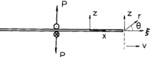
Consider a linear elastic homogeneous isotropic infinite medium that contains a semi-infinite crack, which lies along the negative x-axis with the origin of the coordinate system at the crack tip. Initially, the body is in equilibrium under the action of the applied static loads at the crack faces. The load magnitude is slowly increased until it is sufficiently large to initiate fracture, and therefore the crack extends with constant speed. The crack propagation speed is large enough for inertial effects to be important.
The solution of stresses for constant speed crack propagation can be obtained by superposi- tion of a particular fundamental solution. Suppose that the crack is extending at a constant velocity v, and the crack tip passes the origin at time t = 0. At t = 0, concentrated antiplane
Stress intensity f a c t o r field f o r unstable crack growth 347 forces of unit magnitude appear at the tip of the crack. For t > 0, the crack tip continues to move in the positive x-direction at speed v. The forces continue to act at x = 0 on the faces z = + 0. The boundary conditions of this problem can be written as
z y z ( x , O , t ) = f ( x ) H ( t ) for - ~ < x < v t , (1)
w(x, O, t) = O for vt < x < oe, (2)
where 6 is the Dirac delta function and H is the Heaviside step function. The two-dimensional antiplane wave motion is governed by
O2W O2W (~2 W
Ox-- ~ + ~ z 2 = b 2-63t2 , (3)
where w is the out-of-plane displacement, and b is the slowness of the transverse wave given by
b = 1 / v s = w / ~ l t .
Here # and p are the shear modulus and the mass density of the material, respectively. The nonvanishing stresses are
0w 0w
Zxy = Iz ~ x ' Zy~ = I~ ~z" (4)
It is convenient to eliminate the x coordinate in favor of a new coordinate ~ defined by
= x - vt. The ~, z-coordinate system is then fixed with respect to the moving crack tip. The complete transformed solution is found by means of Laplace transforms and the Wiener-Hopf technique. The exact solution can then be found by inverting the Laplace transforms by de Hoop's method. The full field solution for the fundamental problem can be expressed as follows
ZxVy(~, z, t) = - - Im i2 -- ~ (2) ' (6) where 2 = - ( ~ t + b2z2/d) + iz{t 2 - b2[(~ + t/d) 2 + z2]} 1/z ~2 ..~ (1 -- b 2 / d 2 ) z 2 ' (7) fl+(2) = [b + 2(l - b/d)] 1/2, (8) fl_(2) = [b - 2(1 + b/d)] ~/2, (9)
and d = 1/v. Then the shear stress Zyz on the plane z = 0 is
zrr ( , O, t) = - xfd[t(1 - b / d ) - 1/2
+
(1o)
With the fundamental solution in hand, it is possible to construct the dynamic field of the propagation crack subjected to general time-independent loadings on crack faces. Suppose that the cracked solid is in equilibrium under the action of applied static loads tending to open the crack, and suppose that the resulting stress on the plane z = 0 ahead of the stationary crack tip is - p ( x ) . At time t = 0, the crack begins to extend at a constant speed v and, for t > 0, new traction free faces have been created along 0 < x < vt. As the crack grows, the traction distribution p(x) appears through the crack tip and acts on each crack face tending to open the crack. This solution, when added to the initial stress distribution in the body, yields the complete solution of the problem. Furthermore, the stress distribution for the traction p(x) appearing through the moving crack tip can be obtained by the superposition scheme. The result for the stress component is a superposition integral over the corresponding stress component of the fundamental solution
fo
zy°~(x, z, t) = zrr=(x - Xo, z, t - Xo/V)p(xo) dxo, (11)
where
~ = (t/b - bx/d) - [~2 + ( 1 - b2/d2)z2-p/2 ~2~d2 ~ •
In order to examine the details of the transient field, a particular time independent loading condition is considered here. Initially, the body is at rest under the action of a pair of opposed static concentrated forces of magnitude P on the crack faces at a distance L behind the crack tip. At time t = 0, the crack begins to extend in its own plane with crack tip speed v. In terms of the stress component and the antiplane displacement components, the boundary conditions on z = 0 for the half-plane problem in z >t 0 are
zr~(x, 0, t ) = P f i ( x + L ) for - @ < x x vt, w(x, O, t) = O for vt < x < ~ .
The static full field solutions of stresses for applied point loading P at the crack faces are
P f L r cos(30/2) + L cos(0/2)
zsrz(r,O)= ~ N/ r r 2 + 2 r L c o s O + L 2 '
(12)
P f L r sin(30/2) + L sin(0/2)
Stress intensity factor field for unstable crack growth
349 The process of crack extension is viewed as the negation of the time independent traction on the crack plane due to the initial loading. In the present problem, the traction that arises from the concentrated forces P is obtained from (12)rS~(x, O) = p(x) - n(L + x)
"
(14)Then, the full field transient solution of stress
zr~(x, z, t)
for the propagation crack can be constructed by adding the result of (11) and the static solution, the results are= ~ y z ( x , z) + - x 0 , z, -
ryz(X, z, t)
s
rVrz(X
t
Xo/V)p(xo)
dxo,(15)
f0 F
rxy(x, z, t) = TSr(x, z) + "cxr(x
- Xo, z, t - Xo/v)p(xo)
dxo. (16)Now, we focus our attention on the stress along the crack tip line. After substituting the explicit expressions for v Tyz(x, 0, t) into (15), the result is
P
~
f o P w / ~ [ ( t - x ° d ) ( 1 - b / d ) - b ~ ] ~ / 2 d x o ,
~y~ (x, O,t) = rc(L + x~
+
n2 x/~ (t -- -x o--d + ~--~(L +Xo)~oo
(17) wheret b ~
d
d - b "
The integral in the second term of (17) can be worked out and expressed in an explicit form, which yields
P
X/~
[ P x / t - - - b x + ( d ~ b ) L
P
f ~ ]
• ,~(x, O, t) = n(L + x~)
+ L
n(x + L ) x / ~
n(L + x)
_ Px/t - bx + (d - b)L
( 1 8 )The dynamic stress intensity factor is defined by the following limit
K(v,
t) = lim [(2g~) 1/2"Cyz(X, O,
t)]~0
=(1 -
b/d) 1/2 w/~(vt + L) 1/2
The expression in (19) is the dynamic stress intensity factor for a crack which is in equilibrium with point applied loads for t ~< 0, and which extends at a constant velocity v for t > 0. The result has the interesting form of the product of a function of the crack velocity (1 - b/d) x/2 and the corresponding static stress intensity factor K s for applying concentrated loading P at the crack face with a distance L + vt from the crack tip. The value (1 - b/d) 1/2 is an universal function which depends only on crack speed and material properties.
The transient full field solutions expressed in (15) and (16) can also be worked out in a procedure similar to the stress along the crack tip line. The integration form in (15) and (16) can be removed by taking the integration in the complex plane and using the theorem of residue. The result contains two terms, one term is exactly the same as the static solution shown in (12) and (13) but with a minus sign. Hence, the transient full field solution of stresses can be expressed explicitly as follows
[(4 + tl) A1/2 D - dtlzC]
Zyz(X, z, t) = rc(2dAB)l/2[(r I + 3) 2 + z2], (20)
[z2r/d + (4 + rl)E]Aa/ZG + z[(¢ + tl)A - ~ldE]F
zxr(x, z, t) = - rc(2dA)l/ZB[(rl + 3) 2 + zZ][(d + b)r/+ b~] ' (21) where
A
= ( d 2 - b 2 ) q 2 -2b2~r/--
b 2 ( ~ 2 d- 2 2 ) , B = ~2 + (1 --b2/d2)z 2,
C = {(d - b)(x/B - ¢)t/+ b[~ 2 + (1 - b/d)z I - x/-B~]} '/2, D = {(d - bXx/-B + ~ ) r / - b[~ 2 + (1 - b/d)z z + x/-B~]} ~/2, E = - ( ~ t l d + zZb2/d), F = {(b + dXx/B + ~)t/+ b[~ 2 + (1 + b/d)z 2 + x/@~]} ~/2, G = {(b + dXx/@ - ~ ) r / - b[~ 2 + (1 + b/d)z 2 - x/B~]} '/2, t 1 = t/d + L.The near tip stress distribution for the propagating crack can be derived as an interior asymptotic expansion by means of standard asymptotic methods (Freund and Clifton [17]). The K-controlled stress field is the asymptotic stress distribution and is defined as follows
K K(t) cos(0J2), T Y Z - - 2 ~ (22) r = - K ( t )
sin(Os/2),
Zxy ~ s x / 2 n r f ~ whereI23/
fl = x/1 - (v sin O/v~) 2,Stress intensity factor field for unstable crack growth 351 0~ = t a n - 1 (~s tan 0),
cq = n i l - l)2/I)2 .
The coordinate system r, 0 is defined and is shown in Fig. 1, with r = v / ~ + z 2 and tan 0 = z/~.
The dynamic stress intensity factor K has a very simple relationship to the associated static a and A value K ~ as indicated in (19). We then propose a simple approximation formulation zy~ ~xr for the complicated transient full field solution as follows:
r~5(x, z, t) : (1 - b/d) "2 ~S~(x, z, t), (24)
%,A(x, Z, t) = (1 -- b/d) 1/2 zSy(x, z, t).
(25)
A has the product of the function (1 b/d) 1/2 and the corresponding The expression of Zyz
s with the crack tip at a distance vt from the original crack tip. This formula- static solution ryz
tion will be shown to be a very good approximation for the transient solution and it will become more useful especially for the complicated inplane case which will be discussed in the next section.
Now, we calculate the transient solution of ry~ at a fixed observation point along the crack tip line at a distance of 6L from the initial position of the crack tip. The crack begins to move at time t = 0, the crack tip approaches this observation point at speed v = 0.5vs. Before the arrival of the shear wave at the observation point, the stress will be the initial time independent static stress. U p o n arrival of the shear wave at normalized time 6, the material particle at the point experiences a transient stress history as shown in Fig. 2. The stress will behave as the square root singular as the crack tip approaches the observation point. In Fig. 2, we also plot the stresses r and the proposed approximate stress calculated from the K-dominance singular field zy~
solution T~. We can see that the proposed approximate solution gives a very good estimation of the transient stress field.
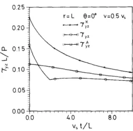
In order to estimate just how the transient field approaches the stress intensity factor controlled field, attention is focused on a moving point which is always a fixed distance r ahead of the moving crack tip. We consider the stress history at a fixed point r = L(O = 0 °, 30 °, 60 °) with respect to the moving crack tip and the crack tip speed is again taken to be 0.5vs. The results are shown in Figs. 3-5. In these figures, the transient stress zyz, the K controlled singular stress %~ and the approximate stress ry~ are plotted in comparison. We can see very clearly that the stress intensity factor singular field is not established during the early phase of crack growth. If we accept that the ratio of the stress ~yz to the stress Zffz up to 0.9, the actual stress is accurately described by the stress intensity controlled field. Then, the nondimensional time vst/L required for the K controlled stress field to be developed near the moving crack tip is about 30. It appears
P z z r
T
x t I - V i0 3 x = 6 L v = v + / 2 O 0 0 " ~ z 0 2 ~
7~
0.1 0 . 0 . . . ~ , , , 00 5.0 100 % t / LFig. 2. The transient stress history at a material point due to the approach of the moving crack tip for anti- plane loading. 0.25 0.20 n 0.15 J m ~-~" O.lO 0.05 0.00 r=L 0=0" v=0.Svs i i r , I ~ , L I ' ~ ' i , i , i i I ' i r t 0.0 4.0 8.0 v s t / L
Fig. 3. The transient stress history at a point at a fixed distance along the crack tip line for v = 0.5vs.
025 0.20 015 d N ~" OlO 0.05 0.00 r=L 0=30 ° v = 0 5 v S . . . . 7y~ o o C T y z 0.0 4.0 8.0 v s t / L
Fig. 4. The transient stress history at a point at a fixed distance (0 = 30 °) ahead of the moving crack tip for v = 0.5v~. 0.30 r=L 0=60* v=05vs yz o. o \ ° ° 0 . I 0 ~ + -5" o . o o + + + + , , . . . + . . . . 00 4.0 8.0 v s t / L
Fig. 5. The transient stress history at a point at a fixed distance (0 = 60 °) ahead of the moving crack tip for
v = 0.5vs,
from the result that the time required for the singular stress field to become a good estimate of the actual stress is quite large. Hence, the use of a singular term to represent the actual stress field should be carefully considered, especially in the early stage of the dynamic transient field. A gives a very good However, we can see from these figures that the approximate stress field rr~
estimation for the transient stress field.
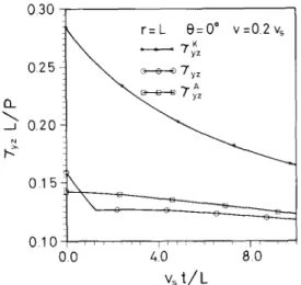
D a t a similar to that in Figs. 3-5 are also shown in Figs. 6-8. In these cases, the crack tip speed is chosen to be 20 percent of the shear wave speed. It appears from these results that the time required before the K controlled singular stress becomes a good estimate of the transient stress increases as the crack speed decreases. This interesting phenomenon indicates that the K controlled stress field needs more time to develop at low crack speed for unstable dynamic crack growth subjected to static loading. However, the proposed
Stress intensity factor field for unstable crack growth
353 0.30 \ r=L O=0* v =0.2 % 0.25 ~ o o o;y; 0 . 1 5 ~ 4 I 0 1 1 0 r ' I ; 0.0 4.0 80 vst/LFig. 6. S a m e as Fig. 3 e x c e p t t h a t results are s h o w n for
v = 0.2vs. 0.30 r=L 8=30 ° v=0.2 % ... 7~z 0.25 ~ o o O?'y z 020 N 0.15 o.10 ,, o.o . . . ' v, t / L
Fig. 7. S a m e as Fig. 4 e x c e p t t h a t results are s h o w n for v = 0.2vs. 13_ d 030 0.20 N 0.10 O 0 0 ' r=L 0=60 ° v=0.2% ~ , o o o Tyz CJ 0 [] O0 40 80 v s t / L Fig. 8. S a m e a s F i g . 5 e x c e p t t h a t r e s u l t s a r e s h o w n ~ r v = O . 2 v ~ .
approximate solution still gives an excellent estimation of the transient stress as shown in Figs. 6-8.
3. lnplane crack propagation with constant velocity
In this section, the general features of the stress history ahead of the crack tip for constant speed crack growth is investigated for inplane deformation. This problem is completely solved by Freund [5] but only the dynamic stress intensity factor was studied in detail. By a similar procedure as discussed in the previous section, the fundamental problem that should be solved can be expressed by the following boundary conditions
o = ( x , O , t ) = O for - ~ < x < o o ,
w ( x , O, t) = O for vt < x < oo.
F o r the inplane case, we focus o u r attention m a i n l y on the transient stress along the line a h e a d of the p r o p a g a t i n g crack tip. T h e expression of the solution for the stress c o m p o n e n t o = is [5] 1 a=~(~,0, t) = rc¢(d + t/~) I m [ H + ( - t / Q ] ' t > a2~ , (26) where H + ( - t / ~ ) = - s + ( - t/ Xc - t / O ( d - c) s + (dR/d + ( - S+(2) = exp - tan -~ j.:,, (2t/2 - b 2 -5 b-~--2/~ -T- 2b2tl/d) 2 ' ~(2) = (a 2 -- 2 2 + a2 ~.2/d2 - - 2a2)]d) x/2, fl(),) = (b 2 _ ,~2 "t- b2),2/d 2 - 2b2)~/d) 1/2, ~+ = [a -t- )~(1 -T- a/d)] i/2,
al = a/(1 + a/d), a2 = a/(1 - a/d), b , = a/(1 + b/d), b2 = b/(1 - b/d),
cl = c/(1 + c/d), c2 = c/(1 - c/d),
in which a = 1/vz a n d b = 1/v~ are the slownesses of longitudinal and shear waves, respectively,
d = 1Iv is the crack tip slowness a n d c = 1/vR is the slowness of the Rayleigh wave in the material which satisfies the e q u a t i o n
(2c 2 - b2) 2 + 4c2(a 2 - - c 2 ) 1 / 2 ( b 2 - c 2 ) 1 / 2 = 0.
I n order to e x a m i n e just h o w the transient near tip field a p p r o a c h e s the stress intensity factor controlled field, a particular time i n d e p e n d e n t loading condition is considered here. Initially, the b o d y is at rest under the action of a pair of o p p o s e d c o n c e n t r a t e d forces of m a g n i t u d e P which act n o r m a l l y on the crack faces at a distance L behind the crack tip and which tend to open the crack. At time t = 0, the crack begins to extend in its o w n plane with c o n s t a n t crack tip speed v. As noted in the previous section, the process of crack extension is viewed as the negation of the time independent traction on the crack plane due
Stress intensity factor field for unstable crack growth 355 to the initial loading. In the present problem, traction arises from the static concentrated forces at x = - L and can be shown to be
X/~ for x > 0. (27)
P
azS (x, O, t) = p(x) - zc(L + x)
With the fundamental solution (26) and static solution (27) in hand, the transient stress history at any point on the prospective fracture plane z = 0, x > vt can be calculated by superposition. It is noted that for a fixed distance ~ ahead of the moving crack tip, there will be no influence of the crack tip motion of t - x/v < a2 ~, so that x < tv - a2 ~v. Hence, we have
Ozz(X, O, t) - zr(L + x~) + afz(X - Xo, O, t - Xo/V)p(xo) dxo, (28)
where
= t v - a 2 C v .
The dynamic stress intensity factor K a is obtained by considering the limiting behaviour ~ ~ 0 + of (28) at the moving crack tip
Ka(t, v) = lim 2x/~azz(~, 0, t)
~ 0 +
vt S+(d)(U + c 2 ) 0 - a/d) 1"
= K'¢(d). (29)
The expression for K a in (29) has the interesting form of the product of a function of the crack velocity K(d) and the corresponding static stress intensity factor K s. The value K(d) = d/[S+ (d) (d + c2)(1 - a/d) 1/2] is an universal function which depends only on crack speed and material properties. The function ~c(d) decreases monotonically from one at v = 0 to zero when the crack speed reaches the Rayleigh wave speed of the material. This important phenomenon of the dynamic stress intensity factor has also been discussed in detail by Freund [5]. The stress on the prospective fracture surface due to the stress intensity factor field is defined as follows
K a
= ( 3 0 )
For the inplane case, we also propose an approximation formulation for the transient solution which is similar to the antiplane case indicated in the previous section. The approximation solution is defined to be
As an illustration, consider a fixed observation point at a distance of 0.75L from the initial position of the crack tip. As the crack begins to move at time t = 0, the crack tip approaches this observation point at speed v. Before the crack tip reaches this observation point, the material particle at the point experiences a transient stress history. All subsequent numerical results are valid for v = 0.25. A typical transient stress history is shown in Fig. 9 for a crack tip speed of 30 percent of the longitudinal wave speed of the material. The stress has been normalized by P/L
and time has been normalized by the time required for the longitudinal wave to travel the distance L. Before the arrival of the longitudinal wave at the observation point, the stress is just the initial time independent stress. Upon arrival of the longitudinal pulse at normalized time 0.75, the stress decreases from the initial static value. It decreases even further upon arrival of the shear wave at normalized time 1.3. The stress does not return to its initial value until after the shear wave passes, and the increase is quite rapid thereafter.
The general features of the stress history for the inplane crack shown in Fig. 9 can be explained in terms of well-known results in wave propagation theory. The initial transient in the process is the sudden application of large compressive loads. The dilatational response is compressive, and this accounts for the initial reduction of stress. The dashed curve in Fig. 9 is the stress which would be predicted by the stress intensity factor controlled singular field of K Only after the shear wave passes does the stress history begin to approach the correspond- azz.
ing K-controlled stress history.
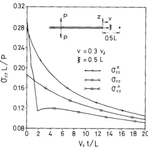
Next, the stress history at a point fixed with respect to the moving crack tip is considered. The particular point at ~ = 0.5L is selected, and the crack tip speed is again taken to be 0.3yr. The transient stress history is calculated numerically and is plotted in Fig. 10. The longitudinal wave arrives at this point at normalized time 0.714, and the shear wave at 1.8. Before the arrival of the longitudinal wave, the stress at the observation point is the same as the static solution, and the stress changes rapidly upon arrival of the longitudinal pulse. The two stress histories approach
13_ 1.0 0.5 0.( 0 P z t v v = O. 3 v~ // x = 0 7 5 L // , , L , , , t , 1 2 V~ t / L
Fig. 9. The transient stress history at a material point due to the approach of the moving crack tip for inplane loading.
Stress intensity factor field for unstable crack growth
357 13-- Nt3
0.32-
028 l
o.22
0.2(
°-16- I
0 .I P
0.5L
v =0.3 v~
.~ =0.5 L
~,~ c cs 0"zz½ 4 6 8 1'0 1'2 12, (6 1'8 20
V4t/L
Fi9. 10. The transient stress history at a point at a fixed distance along the crack tip line for v = 0.3v~.
0.44-
0.40-
0.36-
~_ 0.32
Nb~
0.28.0.24-
0.20-
0.16
0
IP
z v
tS.~ .\
" ~
v =0.1V 1
~ =05L
4 6 8 1'o 7'z 12, 16 18 2o
v4 t/L
Fig. I1. The transient stress history at a point at a fixed distance along the crack tip line for v = 0.lye. each other after the transients associated with the onset of crack growth have died away. As shown in Fig. i0, the approximation solution gives a very good estimation for the transient solution. Figure 11 shows a similar result but for a crack speed taken to be 0.lye.
4. Conclusions
In this study, the exact transient stress field is obtained by superimposing the fundamental solution. The analysis is based on Laplace transform method and the Wiener-Hopf technique. With the fundamental solution in hand, the stress field for crack advance which negates any time independent load can be constructed by linear superposition. The analysis of constant speed
crack propagation is important in some situations. In some cases, crack growth in a real material is indeed steady for a long enough time so that the constant speed results obtained in this study are useful in the interpretation of the phenomenon. Although the analysis is carried out for a semi-infinite crack in an unbounded body, it is applicable to crack propagation in a bounded body only until waves reflected from the boundaries return to the moving crack tip.
We investigate a particular time-independent loading condition to explain the general features of the stress history ahead of the crack tip for unstable dynamic crack growth. Of special interest in this analysis is the time required for the stress at a point near the moving crack tip to reach the value it would have if the stress field were actually given by the near-tip stress intensity factor field. This analysis is particularly important for experimental results of dynamic crack growth. Many experimental observations are interpreted by assuming the crack tip stress intensity factor controlled field is fully established over the observed region. We found that the transient nature of the stress field during the early phase of dynamic crack growth prevents the stress intensity factor field to be established and there are limitations on the use of the stress intensity factor concept in this situation, which suggests that higher order transient terms should be included in the analysis in order to obtain accurate results. A simple approximate formulation for the transient solution is proposed which is shown to be a good estimation for the complicated transient field.
The extent of the stress intensity factor field during dynamic crack propagation under transient conditions is more limited than a steady state analysis would indicate, as was first suggested by Ma and Freund [9]. A higher order asymptotic expansion of the crack tip field under plane stress conditions is obtained for transient crack growth by Freund and Rosakis [16]. The leading term is the familiar stress intensity factor contribution and the higher order terms take into account the past history of stress intensity factor and crack motion. The analytical result is used to interpret some experimental observations and to conclude that the higher order expansion provides a good representation of crack tip fields under fairly severe transient conditions. Experimental results of the crack tip field were obtained by means of the full field conjugate gradient sensing method. It was found that over the region near the crack tip where the elastodynamic field is expected to be essentially a two dimensional plane stress field, both the observed radial and angular variation of the data are consistent with the higher order expansion. The experimental results and the expansion are in close agreement over a region of significant size around the crack tip. However, during the earlier phase of crack propagation, nowhere within this region of agreement is the field dominated by a stress intensity factor field. The method of caustics has been successfully applied for measuring the stress intensity factor for the static case. The accuracy of the caustic method for the determination of the stress intensity factor is based on the restriction that the stress intensity factor field is fully established at which point the experimental data are taken. It was found by Ma [18] that the experimental measurement of the caustics to evaluate the stress intensity factor for stationary crack subjected to dynamic loading may result in an error of 20 percent. For the case of dynamic crack propagation, the error could be up to 50 percent as investigated by Ma and Freund [9]. Hence very careful measurement of the dynamic stress intensity factor in transient crack propagation experiments by using the singular field alone is needed in order to get good results. The full field optical methods such as photoelasticity or conjugate gradient sensing method are advantageous because the measurement of the dynamic stress intensity factor does not hinge on the assumption of the singular field dominance.
Stress intensity factor field for unstable crack growth
359 AcknowledgmentThe research support of the National Science Council, Republic of China through Grant NSC81-0401-E002-18 at National Taiwan University is gratefully acknowledged.
References
1. E.H. Yoffe, Philosophical Magazine 42 (1951) 739. 2. K.B. Broberg, Arkivfor Fysik 18 (1960) 159.
3. B.R. Baker, Journal of Applied Mechanics 29 (1962) 449.
4. J.D. Achenbach and R. Nuismer, International Journal of Fracture Mechanics 7 (1971) 77-88. 5. L.B. Freund, Journal of the Mechanics and Physics of Solids 20 (1972) 129.
6. Ibid., 20 (1972) 141. 7. Ibid., 21 (1973) 47. 8. Ibid., 22 (1974) 137.
9. C.C. Ma and L.B. Freund, Journal of Applied Mechanics 53 (1986) 303. 10. C.C. Ma and P. Burgers, Journal of Applied Mechanics 55 (1988) 111. 11. C.C. Ma, Journal of Applied Mechanics 55 (1988) 587.
12. Ibid., 57 (1990) 117.
13. C.C. Ma and Y.C. Hou, International Journal of Engineering Science 28 (1990) 1321.
14. A.J. Rosakis, J. Duffy and L.B. Freund, Journal of the Mechanics and Physics of Solids 32 (1984) 443. 15. K. Ravi-Chandar and W.G. Knauss, International Journal of Fracture 25 (1984) 247-262.
16. L.B. Freund and A.J. Rosakis, Journal of the Mechanics and Physics of Solids 40 (1992) 699. 17. L.B. Freund and R.J. Clifton, Journal of Elasticity 4 (1974) 293.