An Efficient Approach to Multicast Routing with Backup Paths in Wireless Ad Hoc Networks
6
0
0
全文
(2) protocols. Furthermore, although the packet is lost, the packet delivery ratio can still be improved if any effort to reduce the influence of delivery failure of the multicast group is made. In this paper, we propose a new method to construct a multicast tree and establish the associated alternate paths at the same time. A long backup path can tolerate continuous link breakages, but the success rate of constructing long backup paths is low and the additional routing overhead is high. Accordingly, we only maintain 2-hop backup paths for each member of the multicast tree. To discover the 2-hop routes, we introduce a concept called “Medium node”. The formal definition of Medium node will be given later. Ad hoc networks can be modeled as a directed graph G = (V, E), where V is a finite set of nodes and E is a set of bi-directional and one-hop links. Each node has a unique ID to represent a distinct mobile host. Each mobile host has a wireless communication device with a predefined transmission range. To facilitate the description of our proposed method, we have the following two definitions. Definition 1. Neighbor nodes Given a network G= (V, E), for a node X ∈ V, the neighbor nodes of X are the nodes that locate within the transmission range of X and are one-hop connected to X. We use the notation NB X to denote the set of the neighbor nodes of X. That is, NB X = {Y| (X, Y). ∈ E, X,. Y ∈ V}.. Definition 2. Medium node Given a network G= (V, E), for any two nodes X, Y ∈ V, Z is a Medium node of X and Y if only if Z ∈ NB X and Z ∈ NBY . Note that, in definition 2, Z is one-hop connected to X and Y.. 3.2. Data structure In the proposed protocol, each node should maintain following data structures to provide routing ability. Routing Table: This table is used for multicast routing and is consisted of 5 fields: DIA, NH, HCD, MF and SN. DIA stands for Destination IP Address; NH stands for Next Hop and stores the first node on the route to the DIA; HCD stands for Hop Count to the Destination; MF stands for Member Flag. This flag is used to indicate whether the node has been added on to the multicast tree. SN stands for Sequence Number. Member Table: this table is maintained by each member of the multicast group and is consisted of 3 fields: MGID, MRIA and HCR. MGID stands for Multicast Group ID; MRIA stands for Multicast Root IP Address; HCR represent the Hop Count to the Root. A node updates its Member Table only when it becomes a member of a multicast tree. Backup Table: this table is used to record the backup path information and is consisted of 3 fields: NBP, NH. and BP. NBP represents the Number of Backup Paths; NH represents the Next Hop node; BP represents Backup Path and stores the pointer that points to the head of the linked list of the backup paths. M-Table: a node will check if it is a Medium node by using this table. The detail of the checking process will be described in section 3.4. M-Table is consisted of four fields: PRH, PH, SIA and DIA. PRH represents Previous Hop and records the TIA of the ACT (see section 3.3); PH represents Post Hop and records the next hop of the ACT; SIA stands for Source IP Address and stores the address of the node that generates the ACT; DIA stands for Destination IP Address and records the address of the node that the ACT will be sent to.. 3.3. Multicast tree construction When a node requires a route to a multicast group and it does not have a route to the destination, it will broadcast a route request packet. If a node that is not a member of the multicast group, it will rebroadcast the route request. The route reply is used to inform the requesting node that there exists a route to the destination, and the node that have received route requests will unicast a route reply to the requesting node through the reverse route if it is a member of the multicast group. When a node receives a route reply, it will update its routing table and build a reverse route. So, after the route reply is sent back to the source node, a route between the source and the destination is built. Since each reply will build an individual route, the source must choose one reply as the primary route. The path selecting procedure is described below: Step 1. Choose the route(s) that have the smallest hop count from the replies Step 2. From the chosen route(s) in Step 1, choose a route that the responding member has the largest number of Medium nodes Step 3. Send an ACT to the NH in the Routing Table to active the route The details of Medium node discovery will be discussed in section 3.4. By Step 2, we can choose a more efficient route than other protocols. After choosing the specific route, the node will unicast an Activation packet (ACT) to the selected next hop to active the primary route. The ACT packet contains 3 fields: SIA, DIA and TIA. SIA stands for source IP address; DIA stands for destination IP address; TIA stands for IP address of the transmitter. A node will set TIA to its own address if it forwards the ACT. By using the ACT packet, only one route will be added to the multicast tree and routing loop is thereby avoided. The next hop, on receiving the ACT packet, sets the MF in the routing table and then delivers the ACT packet to the selected next hop. This process will continue until the DIA is reached. If the source does not receive the route reply within a certain period, it will broadcast another route request with longer TTL (time to live). After a certain. - 677 -.
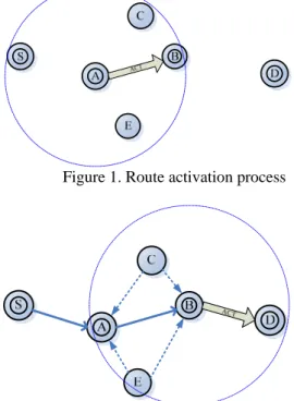
(3) number of retries, the source assumes that there are no other multicast group members that can be reached and declares itself as the root.. 3.4. Backup path setup Since other nodes that are close to the primary route will also hear the ACT packet, we can find the Medium node without any additional control packet by using the routing information in the ACT packet. When a node, which is not a tree member, receives an ACT packet, it will record the TIA and the next hop of ACT in the PRH and the PH field of the M-Table, respectively. If the node receives another ACT, it will check weather the TIA is equal to the PH field. If it is, the receiving node will send a set_backup packet to PRH and PH to inform that it is a Medium node of PRH and PH. The set_backup packet has two fields: PRN and PN. PRN stands for Previous Node and store the address of PRH. PN stands for Post Node and stores the address of PH. The pseudo code of the Medium node checking algorithm is described below. Medium-Check(G) 1. { For a node not in the multicast tree with M-table m 2. When receive an ACT x { 3. mflag=0; 4. if there is an entry in m with the same data of (x.TIA, next hop of x, x.SIA, x.DIA) {discard the packet; exit;} 5. for i=1 to (max no. of entries in m) 6. if (m.SIA[i]==x.SIA&& m.DIA[i]==x.DIA){ 7. if(x.TIA == m.PH[i]){ 8. send set_backup packet to m.PRH[i] and m.PH[i]; mflag=1; //this node is a medium node 9. }} 10. if (mflag==0) // insert a new entry into m 11. insert ( x.TIA, next hop of x, x.SIA, x.DIA) as a new entry in M-Table; 12. }} Analysis of the algorithm Medium-Check(G): Assume that the number of the member of the multicast tree is k. That is, a node may receive k-1 ACT packets. And, for a node, the maximum number of entries in the M-Table is k. In the above pseudo codes, line 2 may execute k-1 times. Lines 5 to 9 may execute k times. So, the time complexity of the Medium node 2. checking algorithm is O(k ). Example: When node A forward ACT to node B, node C and E will also receive the packet, as shown in Figure 1. Figure 2 shows that, when B send ACT to D, C and E will also receive the ACT from B, and they find that the TIA of the packet is the same as their PH field of the M-table. So, they send set_backup packets to both A and B to inform that they are Medium nodes. The way we establish the backup path is similar to AODV-BR, which forms a mesh structure. But we change the process by adding a Backup Table to nodes. on the primary route. This table will improve the efficiency of the path recovery process. In AODV-BR, it performs a 1-hop broadcast to its immediate neighbor to finding an alternate path and this action may cause some delay and collision. By maintaining the Backup Table, we can shorten the response time of path discovery and save the channel bandwidth.. Figure 1. Route activation process. Figure 2. Route activation and backup path setup To provide fresh routing information, each member should update its Backup Table periodically. Using the hello message can easily discover and maintain Medium nodes. A member of the multicast tree receives a hello message will record the sender in the PRH field of the M-Table and waits for the reply for this hello message. If the node receives a reply and the destination is equal to its PRH field of the Check Table, it records the sender of the reply in the PH field in the Check Table and then delivers a set_baackup packet to PRH and PH. The pseudo code of the Medium node maintaining process is described below. Medium-maintain(G) 1. {For a node not in the multicast tree with M-table m 2. When receive a hello message y { 3. if there is no entry in m that the PRH field is equal to the sender of y 4. {record the sender of y to the PRH field as a new entry} 5. else 6. {discard the packet}} 7. When receive a reply of hello message z 8. { 9. for all the entries i in m 10. if(destination of z==m.PRH[i]) 11. { 12. Record the sender of z in the m.PH[i]. - 678 -.
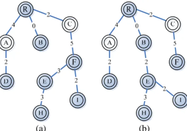
(4) 13. send set_backup packet to m.PRH[i] and m.PH[i] 14. } 15. else 16. {discard the packet} 17. }} When a node receives the set_backup packet, it will update its Backup Table. Besides, if the old entry has not been updated for (Hello_interval × (1+allowed hello loss)) milliseconds, it would be deleted. This procedure can make sure that the routing information is up to date.. 3.5. The influence of link failure In the construction process of the multicast tree, our goal is to form a multicast tree with backup paths for each link and to locate nodes that have less Medium nodes in the lower level of the tree to reduce the influence of link failure. According to the route activation process, the multicast tree member that has more Medium nodes will have more chance to be connected by the joining node. Thus, the member with less Medium nodes will be located near a leaf. Since link breakage occurs more frequently around nodes with less Medium nodes, locating the nodes in the lowest level of the multicast tree will reduce the influence of link failure.. (a) (b) Figure 3. Examples of multicast tree construction For example, as shown in Figure 3, nodes E, H and I join a multicast tree (with nodes R, A, D, B and C).By MRP-BP, the constructed multicast tree is shown in Figure 3(a); while the multicast tree constructed by MAODV is shown in Figure 3(b). Obviously, node B is apt to lose contact with node R since there is no backup path between nodes R and B. On the contrary, node F will not disconnect easily due to multiple backup paths. That is, compared with MAODV, with the proposed MRP-BP, nodes I, E and H won’t be affected by the failure of nodes B and R. 3.6. Multicast tree maintenance A link breakage is detected if there is no packet receiving operation from its neighbor in Hello_interval × (1+allowed hello loss) millisecond. When a link breakage is detected, the node that is farther away from the root a will check its Backup Table. to recover the link and send a route request to the root to rebuild the route. If there is more than one BP in the Backup Table, the node will schedule random delay prior for each BP to avoid packet collision. Nodes that are waiting for relaying the packet would terminate the process if they receive the acknowledgment from the destination caused by other salvage transmission. In this manner, the waste of bandwidth and packet collision is therefore avoided. A node may want to terminate the member ship with the multicast group. If the node were not a leaf, it would revoke its member status and still serve as the router for the multicast tree to keep it working. Otherwise, if the node is a leaf node, it will prune itself from the multicast tree by setting MF to zero.. 4. Performance analysis 4.1 Simulation model We have developed a simulation model that is based on C++ as an experimental platform. The simulation environment consists of 50 nodes in 1000 m × 1000 m area. The transmission range of the mobile host is 250m. A source multicast 1000 256-byte data packet to the multicast group and the transmission rate is 1 sec. Network bandwidth is 2Mbps and the MAC protocol is 802.11. The random waypoint model [9] is used and the max speed is set to 0m/s, 1m/s, 10m/s or 20m/s.In our simulation model, the multicast source is chosen at random from the multicast group. Nodes join as members at the start of the simulations and remain members throughout the duration of the simulation. Performance metrics: Packet Delivery Ratio: this is the ratio of the number of the multicast data packets delivered to total number of transmitted multicast data packets. Retransmission ratio: the ratio of the number of data packets retransmission to while the link is broken. This metric can reflect the improvement by the backup path more clearly. Normalized packet overhead: this is defined as the total number of control and data packets sent and forwarded normalized by the total number of packets successfully delivered across all the multicast receivers.. 4.2 Simulation results 4.2.1. Effects of varying speed Figure 4 shows that the packet delivery ratio of MRP-BP in comparison with other routing protocols under different velocities. First, we consider the situation: when the link breakage is detected, the source node will retransmit the data. In this situation, MRP-BP shows better performance even in high dynamic environment. This is because MRP-BP is more stable and it does not retransmit the packet if there is a backup path. The tree maintenance mechanism of AMRIS[3] operates in background instead of using the link. - 679 -.
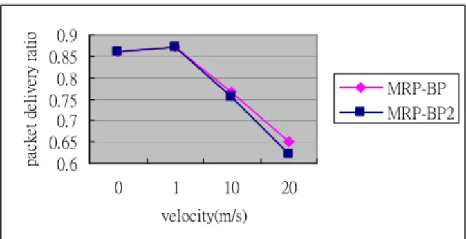
(5) packet delivery ratio. 1.2. 0.9 0.85 0.8 0.75 0.7 0.65 0.6. MRP-BP MRP-BP2. 0. 1. 10. 20. velocity(m/s). Figure 6. Comparison of different path selecting policy. 1. The normalized packet overhead rises with the increment of speed because the link breaks more often and the rebuilding process causes more control packets. MRP-BP generates the lowest normalized packet overhead in different speed, as shown in Figure 8. MZRP shows extremely high overhead due to the frequently information collecting of the zone of each node. The group hello message of MAODV and the NEW-SESSION message of AMRIS will propagate through the entire network and the broadcasting packets are the main reason of the rising of the normalized packet overhead. For this reason, the overhead of AMRIS and MAODV are similar even though the ways they maintain the multicast tree are different.. MRP-BP. 0.8. MAODV. 0.6. AMRIS. 0.4. MZRP. 0.2 0 0. 1. 10. 20. speed(m/s). Figure 4. Packet delivery ratio as a function of speed with packet retransmission 1.2 1 MRP-BP. 0.8 0.6 0.4. MAODV. 0.6. AMRIS. 0.5. retransmission ratio. packet delivery ratio. packet delivery ratio. breakage detection, and therefore the packet delivery ratio goes down a little slower than MAODV[5] and MZRP[4]. Let us consider another situation. When the link failure causes a packet loss, the source node won’t retransmit the data. MRP-BP can significantly improve the packet delivery ratio since the backup paths will relay the packets when the primary link is down. The simulation results are shown in Figure 5.. MZRP. 0.2 0 0. 1. 10. 20. speed(m/s). MRP-BP. 0.4. MAODV. 0.3. AMRIS. 0.2. MZRP. 0.1 0. Figure 5. Packet delivery ratio as a function of velocity without packet retransmission. 1. 10. 20. speed(m/s). Figure 7. Number of retransmission as a function of speed Normalized packet overhead. As described in section 3.5, we use the number of Medium nodes for selecting the route. This criterion is useful for selecting a better path so as to derive better packet delivery ratio. Figure 6 illustrates this result. MRP-BP2 does not use the information of the number of Medium nodes when selecting the route. When the mobility is low, links will not easily break, so the results are the same. The improvement is significant when the speed increases to 10m/s and 20m/s and the packet delivery ratio is about 2%. Figure 7 shows that as the speed increases, the number of packet retransmission grows fast. MRP-BP will not retransmit the data packet until there is no backup path to recover the broken link, so the retransmission ratio is lower than others. AMRIS may rebuild the route before the data packet transmission, so the retransmission ratio is not high. Since MAODV and MZRP use only link breakage detection mechanism to initiate the route recovery process, the retransmission ratio is higher than others.. 0. 16 14 12 10 8 6 4 2 0. MRP-BP MAODV AMRIS MZRP. 0. 1. 10. 20. speed(m/s). Figure 8. Normalized packet overhead as a function of speed. - 680 -.
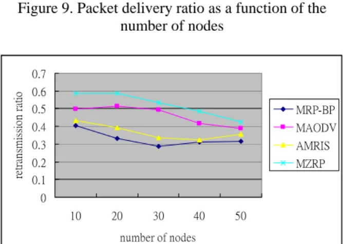
(6) packet delivery ratio. Figure 9 shows that MRP-BP works better than other protocols even if there is nearly no router for the multicast group. The simulation results show that when the number of nodes is more than thirty, the packet delivery ratio is nearly stable for MRP-BP and AMRIS. The number of the data retransmission can reflect the frequent change of network topology. MRP-BP does not need to retransmit data if there is a backup path, so it has the lowest retransmission ratio. Figure 10 illustrates the simulation results. Figure 11 shows the normalized packet overhead as a function a number of nodes. Although more nodes will provide more alternate path, the number of control packets will also increase. The simulation results show that when the number of nodes is more than thirty, the normalized packet overhead increases slightly. However, since other protocols use broadcasting packet to maintain the routing information, their overheads are much higher than MRP-BP. 0.8 0.7 0.6 0.5 0.4 0.3 0.2 0.1 0. MRP-BP AMRIS. 30. 40. 50. number of nodes. Figure 9. Packet delivery ratio as a function of the number of nodes. retransmission ratio. 0.7 0.6 0.5. MRP-BP. 0.4. MAODV. 0.3. AMRIS. 0.2. MZRP. 0.1 0 10. 20. 30. 40. MRP-BP MAODV AMRIS MZRP. 10. 20. 30. 40. 50. number of nodes. Figure 11. Normalized packet overhead as a function of number of nodes. proposed method is useful for multicast tree construction and route recovery. The main contributions are that the backup paths provide immediate link recovery when the primary link is down and the information of Medium nodes can be used to determine an efficient route. Simulation results show that MRP-BP outperforms other related protocols, such as MAODV, AMRIS and MZRP, in several scenarios.. [1] Internet Engineering Task Force MANET Working Group, Mobile ad-hoc networks (MANET), Available from: http://www.ietf.org/html.charters/manet-charter.html. [2] W. Chen, S. Cai, Ad hoc peer-to-peer network architecture for vehicle safety communications, IEEE Communications Magazine, 2005, 43(4), pp. 100-107. [3] C.W. Wu, Y.C. Tay, AMRIS: A Multicast Protocol for Ad hoc Wireless Networks, Proceedings of MILCOM'99, 1999, pp. 25-29. [4] X. Zhang, L. Jacob, Multicast Zone Routing Protocol in Mobile Ad Hoc Wireless Networks, IEEE Conference on Local Computer Networks, 2003, pp.150. [5] E.M. Royer, C.E. Perkins, Multicast Ad hoc On-Demand Distance Vector (MAODV) Routing, IETF Internet Draft, 2000. [6] S.J. Lee, M. Gerla, AODV-BR: Backup Routing in Ad hoc Networks, Wireless Communications and Networking Conference, 2000, pp. 1311-1316. [7] C.M. Perkins, E.M. Royer, Ad Hoc on Demand Distance Vector (AODV) Routing, IETF Internet Draf, 2000. [8] Y.S. Chen, T.S. Chen, C.J. Huang, SOM: Spiral-Fat-Tree-Based On-Demand Multicast Protocol in a Wireless Ad-Hoc Network. Computer Communications, 2002, 25(17), pp. 1684-1695. [9] D.B. Johnson, D.A. Maltz, J. Broch, Dynamic source routing protocol in ad hoc wireless networks, Mobile Computing, Kluwer Academic Publisher, 1996.. MZRP. 20. 16 14 12 10 8 6 4 2 0. 6. References. MAODV. 10. Normalized packet overhead. 4.2.2. Effects of varying number of nodes. 50. number of nodes. Figure 10. Number of data retransmission ratio as a function of the number of nodes. 5. Conclusion Restoration of wireless links in face of node or link failure poses many challenges to multicast communications. In this paper, we introduce the Multicast Routing Protocol with Backup Path (MRP-BP) which uses backup paths built as a complement to the primary multicast tree for fault tolerance purpose. The. - 681 -.
(7)
數據
相關文件
An additional senior teacher post, to be offset by a post in the rank of APSM, is provided to each primary special school/special school with primary section that operates six or
An additional senior teacher post, to be offset by a post in the rank of APSM, is provided to each primary special school/special school with primary section that operates six or
This kind of algorithm has also been a powerful tool for solving many other optimization problems, including symmetric cone complementarity problems [15, 16, 20–22], symmetric
We have also discussed the quadratic Jacobi–Davidson method combined with a nonequivalence deflation technique for slightly damped gyroscopic systems based on a computation of
Shih, “On Demand QoS Multicast Routing Protocol for Mobile Ad Hoc Networks”, Special Session on Graph Theory and Applications, The 9th International Conference on Computer Science
n The information contained in the Record-Route: header is used in the subsequent requests related to the same call. n The Route: header is used to record the path that the request
“Ad-Hoc On Demand Distance Vector Routing”, Proceedings of the IEEE Workshop on Mobile Computing Systems and Applications (WMCSA), pages 90-100, 1999.. “Ad-Hoc On Demand
In an ad-hoc mobile network where mobile hosts (MHs) are acting as routers and where routes are made inconsistent by MHs’ movement, we employ an associativity-based routing scheme
