1. INTRODUCTION
Generation of electrical energy faces many problems today. In a world of growing environmental awareness, nuclear power plants find less and less acceptance and conventional combustion power plants are criticized owing to air pollution. The natural world is filled with a large amount of clean and safe renewable energy such as solar light, ocean waves, wind flow, etc. and therefore regenerative energy systems are becoming more important then ever. The common features of these energy sources are that the amount of energy in a locally small area is small and usually not stable and is therefore useless, while the amount of renewable energy over large areas is very large and is useful if it is collected effectively and stored safely.
Many converters such as solar modules, wave converters, wind turbines, etc. have been successfully developed to transfer renewable energy into electricity so far.1 – 5
If all renewable energy were converted into DC electric sources by highly efficient DC-to-DC or AC-to-DC converters with maximum power point tracking (MPPT),6 – 7
high-power regenerative systems could be created by directly connecting these DC current sources in parallel or directly connecting DC-to-DC voltage sources in series via DC mains. However, the electric stress applied to every converter along the DC mains will be increased as the total number of converters is increased, which implies that more costs will be incurred.
Innovative transmission line collection systems with lower costs and high efficiency are proposed in this paper. We assume that the renewable energy can be converted into AC electricity by DC-to-DC or AC-to-AC inverters with MPPT first. These collection systems are constructed from a large number of inverters which are dispersed over very large areas and connected by a transmission line network. The power from the renewable sources is automatically accumulated into a large power flow at the target load via the transmission line collection networks by using transmission line theory and the phase relation between sinusoidal outputs of inverters. Based on mathematical analysis, the electric stress of only those inverters which are closer to the target load is larger. Therefore the total costs of the proposed collection systems can be reduced effectively.
2. TRANSMISSION-LINE-TYPE VOLTAGE SOURCE AND CURRENT SOURCE 2.1. TL-type voltage source
A uniform transmission line of length l with characteristic impedance ZO can be described by the
two-port equations V1 V2 = A(l ) B(l ) C(l ) D(l) V2 V1 (1) CCC 0098 – 9886/97/010043 – 07 Received 21 August 1995
© 1997 by John Wiley & Sons, Ltd. Revised 8 January 1996
LETTER TO THE EDITOR
NEW TRANSMISSION LINE SYSTEMS FOR ACCUMULATING POWER FROM
DISTRIBUTED RENEWABLE ENERGY
MING YING KUO, CHING CHUAN KUO AND MEI SHONG KUO‡
where A(l) = D(l) = cos(2πl/λ), B(l) = jZOsin(2πl/λ) and C(l) = jYOsin(2πl/λ) are functions of the
length l. Figure 1(a) shows the schematic diagram of a transmission-line-type voltage source (TLT-VS) with n current sources, which are equally spaced along a transmission line of length λ/4 with characteristic impedance ZO each, and a load resistance RL= ZO. The notation IS, k + 1 represents the phasor current of the
(k + 1)th current generator, where k = 0. …, n − 1. The length of transmission line between the current generatorS, k + 1 and the open-circuited terminal is kλ/4n and that between IS, k + 1 and the load RL is (n − k)λ/
4n. First, the equivalent circuit in Figure 1(b) can facilitate the output response at the load to the individual current source IS, k + 1. The phasor voltage drop Vn + 1 and the phasor current flow Ir, n + 1 are obtained from
Vn + 1= ZOIr, n + 1= ZOcos kπ 2n e −jπ 2/ IS, k + 1 (2)
The TLT-VS In Figure 1(a) can be regarded as a linear system. Ir, n + 1 and Vn + 1 are really the sum of the
response to individual current sources. Letting IS,1= IS,2= ··· = IS, n= IS, the phasor voltage Vn + 1 across RL is
Vn + 1= ZO m
4
= 0 n − 1 cos 4 π + n (mφ)e −jπ 2 /IS= −j Z O 2 cot 1 IS (3)where φ = π/2n. Notice that since the input impedance looking towards the transmission line of length λ/4 with an open-circuited terminal is equal to zero, the equivalent circuit of the TLT-VS at port n + 1 is an ideal voltage source whose phasor voltage is Vn + 1. Additionally, the desired equivalent voltage phasor Vn + 1,
created by properly selecting the current phasor IS, is proportional to the total number n of sources.
Figure 1. (a) Transmission-line-type voltage source (TLT-VS). (b) The equivalent circuit is obtained by only considering the individual source IS, k + 1. (c) Transmission-line-type current source (TLT-CS)
2.2. TL-type current source
The algorithm for finding the topological dual is well known and can be found in texts on the duality transformation of basic network theory.8
The duality principle operates on a network of two-terminal elements to produce another network with the same number of elements. The original and transformed circuits are said to be duals of each other and their properties are closely related in many ways.
According to the dual transformation, one interchanges the voltage and current wave-forms of the uniform transmission line, i.e. let υ be i* and i be υ*, and simultaneously the value of Z*O equals that of
ZO − 1
. As a result, the dual of a transmission line with characteristic impedance ZO is also a transmission line
with characteristic impedance Z*O numerically equal to ZO − 1
, which has the same two-port equations as (1) but its ABCD matrix with A(l) = D(l) = cos(2πl/λ), B(l) = jZ*Osin(2πl/λ) and C(l) = jY*Osin(2πl/λ).
The transmission-line-type current source (TLT-CS) can be derived from the TLT-VS by utilization of the duality algorithm, as illustrated in Figure 1(c), where the phasor voltage of every source is V*S and the
terminal R*L equals Z*O. It is emphasized that since the input impedance looking towards the transmission
line of length l =λ/4 with a short-circuited terminal at port n + 1 is equal to infinity, the TLT-CS acts as an ideal current source with phasor current I*n + 1 with respect to the (n + 1)th port. The relationship between
I*n + 1 and V*S for the TLT-CS can be obtained by interchanging the voltage and current wave-forms in
equation (3): n + 1= −j 1 4 π + n I É 2Z OÉ cot 1 VS É (4)
The phasor current I *n + 1 through R *L is proportional to the total number of sources.
3. ONE-DIMENSIONAL COLLECTION SYSTEMS 3.1. Current-type collection system
Figure 2(a) shows the collection system with distributed current sources, called the current-type transmission line collection system (CT-TLCS), where the transmission line is matched with both load
Figure 2. (a) Current-type transmission line collection system (CT-TLCS). (b) Voltage-type transmission line collection system (VT-TLCS)
terminals, i.e. RL1= RL2= ZO. The CT-TLCS was presented in Reference 9 and here we state only its
important aspects. 1. By letting IS, k= Ime
j kθ
and βl = θ, the phasor voltage drops at RL1 and RL2 are V1 and Vn, respectively,
given by V1= n 2 ZOIme jθ (5) Vn= 1 2 ZOIm(e + −j(n − 2) + θ e−j(n − 4)θ e−j(n − 6)θ+ +ejnθ) (6) It is noted that when, βl = θ = π/n, Vn is equal to zero but V1 is not, which implies that the CT-TLCS
transmits power to RL1 but transmits no power to RL2.
2. Similarly, by letting βl = − θ, V1 and Vn are expressed as
Vn= 1 2 ZOIm(e + 3 j 5 θ+e j θ e j θ+ +ej n θ) (7) Vn= n 2 ZOIme j θ n (8)
The importance is that when βl = –θ = π/n, V1 equals zero but n does not, which implies that the
CT-TLCS transmits power to RL2 but transmits no power to RL1. In addition, the length l of every
subtransmission line notably equals λ/2n, as derived from βl = 2πl/λ = π/n.
The renewable power form distributed current sources can be accumulated and propagated towards the target load of RL1 or RL2 via the CT-TLCS, where the length l of all subtransmission lines is equal to λ/2n
and the current source I = Ime j kθ
must satisfy the phase condition θ = − π/n or θ = π/n. 3.2. Voltage-type collection system
Based on the duality principle, the voltage-type transmission line collection system (VT-TLCS) can be easily developed from the CT-TLCS, as shown in Figure 2(b), where the phasor representative of the voltage source is V*S, k= Vme
j kθ
and both terminals satisfy R*L1= R*L2= ZO.Note that Z*O numerically equals
Z0 − 1
and the value of Vm equals Im. The voltage and current wave-forms of both transmission line collection
systems are interchanged with each other. By controlling the phase degree of θ, the net power flow of the VT-TLCS can be towards R*L1 for θ = π/n or towards R*L2 for θ = − π/n. Therefore we can interchange the
voltage and current wave-forms in equation (8) and the current I*n through RL2 for θ = − π/n is given by
In É = n 2 ZOÉ Vme jnθ (9)
4. TWO-DIMENSIONAL COLLECTION SYSTEMS
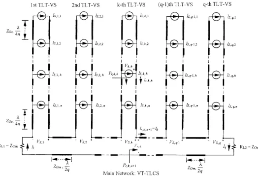
Two-dimensional transmission line collection systems (2D-TLCSs) can be simply derived from the CT-TLCS or VT-CT-TLCS by replacing distributed AC electric sources with TLT-VSs or TLT-CSs. Figure 3 shows the schematic diagram of a two-dimensional voltage-type transmission line collection system (2D-VT-TLCS) in which the main collection system is a CT-TLCS with the distributed AC current sources IS, k= IMe
j kθ
and every distributed AC current source is created by a TLT-CS, where the characteristic impedance of the main TL, denoted by ZOm, is equal to two times that of a sub-TL, denoted by ZOs, i.e.
ZOm= 2ZOs, and all voltage sources VS, k, h in the kth TLT-CS are identical and determined by substituting
Figure 3. Two-dimensional voltage-type transmission line collection system (2D-VT-TLCS)
Figure 4. Two-dimensional current-type transmission line collection system (2D-CT-TLCS)
power supplied by TLT-CSs towards RL2, but RL1 will receive no power, as analysed in Section 3. The
phasor voltage Vq across RL2 is given by Vq= (q/2)ZOmIMe
− jπ from equation (8).
Similarly, Figure 4 shows the schematic diagram of a two-dimensional current-type transmission line collection system (2D-CT-TLCS) that adopts a VT-TLCS as the main collection system and constructs every distributed AC voltage source VS, k= VMe
ZOm= 1 _
2ZOs, and all current sources IS, ,k, h in the kth TLT-VS and VS, k have the relationship of equation (3).
It should be pointed out that the 2D-VT-TLCS and 2D-CT-TLCS are duals of each other. In Figure 3, the PS, k, h=
1 _
2VS, k, hÄ Ik, h is defined as the complex power supplied by the voltage source VS, k, h
where Ik, h is the current through the voltage source VS, k, h. Pr, k, h= 1 _
2Vr, k, hÄ Ik, h is also defined as the complex
power looking towards the main network at the kth TLT-CS. Moreover, Pr, k, n + 1= 1 _ 2Vr, k, n + 1Ä Ir, k= 1 _ 2VkÄ Ir, k is
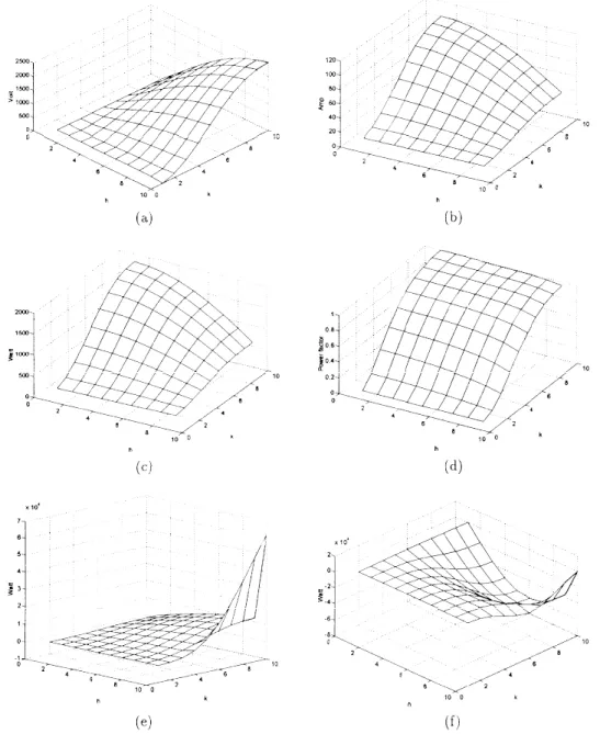
defined as the complex power looking towards RL2 in the main network CT-TLCS. Figure 5 shows the
simulated results of a 2D-VT-TLCS with ZOm= 50Ω, ZOs= 25Ω, n = 9, q = 10 and IS, k= 10e − j
kπ/q amps. The target load RL2 is at (k, h) = (q, n + 1) = (10, 10). The voltage magnitude | Vr, k, h| in the kth TLT-CS has
a minimum at h = 1 and a maximum at h = 10, as shown in Figure 5(a). In contrast, the minimum and maximum of the current magnitude | Ik, h| through the voltage source occur at h = 10 and h = 1 respectively,
Figure 5. Simulated results of 2D-VT-TLCS with ZOm= 50Ω, ZOs= 25Ω, n = 9, q = 10 and IS, k= 10e
− j ( kπ/ q) amps: (a) magnitude
as shown in Figure 5(b). As observed from Figures 5(c) and 5(d), the power rating and power factor supplied by the voltage source VS, k, h increase as the location of the TLT-CS becomes closer to the target
load RL2. It should be stressed that the 2D-VT-TLCS can automatically accumulate the distributed electric
energy towards the target load RL2 along the transmission line network and into a large power flow at the
target, as illustrated by Figure 5(e).
It is emphasized that the two-dimensional transmission line collection systems in Figures 3 and 4 really accumulate the power from distributed renewable energy sources towards the target load and incur less costs, because larger voltage/current and power rating are required for only some AC electrical sources and transmission lines.
5. CONCLUSIONS
This paper proposes one-dimensional and two-dimensional transmission line collection systems for automatically accumulating power from renewable energy, which is distributed over a very large region, into a large power flow at the target load. Both current-type and voltage-type transmission line collection systems for accumulating the distributed renewable power have been discussed in this paper. Based on transmission line theory and controlling the phase of AC sources, the net electrical power of the proposed transmission-line-type networks can flow towards the target load. Moreover, the proposed novel 2D-VT-TLCS and 2D-CS-2D-VT-TLCS incur less costs, because only those sources which are far from the target load and those transmission lines which are close to the target load are required to have larger power rating.
REFERENCES
1. E. Edelson, ‘Photovoltaics: solar cell update’, Popular Sci., June, 95 – 99 (1992). 2. M. DiChristina, ‘Sea power’, Popular Sci., May, 70 – 73 (1995).
3. D. Stover, ‘The forecast for wind power’, Popular Sci., July, 66 – 72 (1995).
4. R. Shaw, Wave Energy: A Design Challenge, Ellis Horwood, Chichester, 1982.
5. H. J. Krock, Ocean Energy Recovery, American Society of Civil Engineers, 1990.
6. S. M. M. Woff and J. H. R. Enslin, ‘Economical, PV maximum power point tracking regulator with simplistic controller’, Proc. 24th Ann. IEEE Power Electronics Specialists Conf., PESC’93, IEEE,. New York, 1993, pp. 581 – 587.
7. C. Y. Won, D.-H. Kim, S.-C. Kim, et al., ‘A new maximum power point tracker of photovoltaic arrays using fuzzy controller’, Proc. 25th Ann. IEEE Power Electronics Specialists Conference, PESC’94, IEEE, New York, 1994, pp. 396 – 403.
8. C. Desoer and E. Kuh, Basic Circuit Theory, McGraw-Hill, New York, 1969.
9 M. Y. Kuo, C. C. Kuo and M. S. Kuo, ‘Novel transmission-line collection systems for photovoltaic power’, Proc. IEEE Int.