Optimal design and experimental verification of a magnetically actuated optical image
stabilization system for cameras in mobile phones
Chi-Wei Chiu, Paul C.-P. Chao, Nicholas Y.-Y. Kao, and Fu-Kuan Young
Citation: Journal of Applied Physics 103, 07F136 (2008); doi: 10.1063/1.2839782
View online: http://dx.doi.org/10.1063/1.2839782
View Table of Contents: http://scitation.aip.org/content/aip/journal/jap/103/7?ver=pdfcov Published by the AIP Publishing
Articles you may be interested in
Design and optimization of voice coil actuator for six degree of freedom active vibration isolation system using Halbach magnet array
Rev. Sci. Instrum. 83, 105117 (2012); 10.1063/1.4764002
Fuzzy control design of a magnetically actuated optical image stabilizer with hysteresis compensation J. Appl. Phys. 105, 07F124 (2009); 10.1063/1.3068542
Performance comparison of various magnetic circuits of integrated microspeakers and dynamic receivers used for mobile phones
J. Appl. Phys. 103, 07F125 (2008); 10.1063/1.2839343
Intelligent actuation strategy via image feedbacks for a magnetically actuated autofocusing module in mobile phones
J. Appl. Phys. 103, 07F123 (2008); 10.1063/1.2835451
Three-axis lever actuator with flexure hinges for an optical disk system Rev. Sci. Instrum. 73, 3678 (2002); 10.1063/1.1505098
[This article is copyrighted as indicated in the article. Reuse of AIP content is subject to the terms at: http://scitation.aip.org/termsconditions. Downloaded to ] IP: 140.113.38.11 On: Wed, 30 Apr 2014 23:10:13
Optimal design and experimental verification of a magnetically actuated
optical image stabilization system for cameras in mobile phones
Chi-Wei Chiu,1Paul C.-P. Chao,1,a兲 Nicholas Y.-Y. Kao,2and Fu-Kuan Young2
1
Department of Electrical and Control Engineering, National Chiao Tung University, Hsinchu 300, Taiwan
2
Department of Mechanical Engineering, Chung Yuan Christian University, Chungli 320, Taiwan
共Presented on 9 November 2007; received 2 October 2007; accepted 19 December 2007; published online 10 April 2008兲
A novel miniaturized optical image stabilizer共OIS兲 is proposed, which is installed inside the limited inner space of a mobile phone. The relation between the VCM electromagnetic force inside the OIS and the applied voltage is first established via an equivalent circuit and further validated by a finite element model. Various dimensions of the VCMs are optimized by a genetic algorithm 共GA兲 to maximize sensitivities and also achieving high uniformity of the magnetic flux intensity. © 2008
American Institute of Physics.关DOI:10.1063/1.2839782兴
I. INTRODUCTION
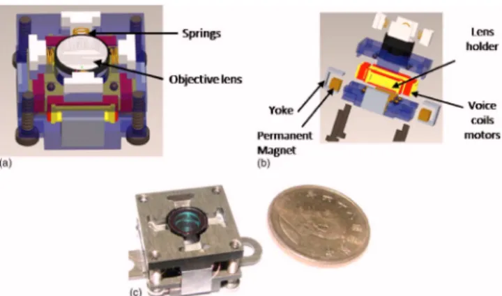
Recently, cameras become indispensable features in a mobile phone. One of the important design objectives is to minimize the image blurring caused by the handshaking of users. To this aim, an optical image stabilization 共OIS兲 mechanism,1,2 is proposed in this study, which is shown in Figs.1共a兲and1共b兲. It is aimed to design a miniaturized OIS module with high actuation forces around handshaking fre-quencies. The magnetic field simulation and analysis per-formed by the softwareANSYSare then conducted to ensure required actuation. An optimization method, the genetic al-gorithm共GA兲,3is next applied to search for the best dimen-sions of the mechanism to simultaneously achieve compact-ness of the OIS and high sensitivity in a satisfied uniformity. Finally, the optimized structure is fabricated to verify the optimal results predicted by the theoretical design.
II. MAGNETIC FIELD ANALYSIS
The lens holder in the OIS module is actively moved by the magnetic force from the VCMs of the OIS module. It is expected that the lens holder is actuated in a uniform and sufficiently strong magnetic field to counteract the handshak-ing vibrations. To this end, an equivalent magnetic circuit for the VCM is first established to predict the driving electro-magnetic forces, which is followed by ANSYS analysis for validation.
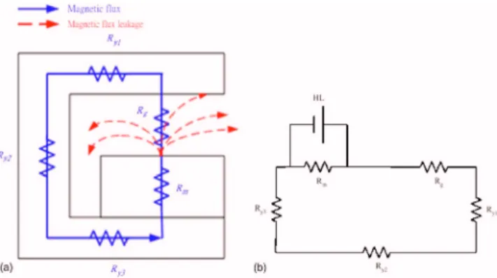
The proposed magnetic structure of each VCM, consist-ing of yoke and a permanent magnet, is shown in Fig.2共a兲, along with its generated magnetic field. To derive an equiva-lent magnetic circuit, the reluctances of the yoke in different dimensions are denoted, respectively, by Ry1, Ry2, and Ry3. On the other hand, Rm denotes the reluctance of a magnet
while Rgdoes the air gap between the magnet and yoke. An
equivalent magnetic circuit is then built, as shown in Fig.
2共b兲, where the reluctances are represented by resistances and the magnet by a voltage source. A yoke reluctance in this equivalent magnetic circuit can be calculated by
Ryi=
Li Ai
, i = 1,2,3, 共1兲
where Liis the length of magnetic flux,is the permeability
of the material, and Ai are the cross sections of the three
different parts of the yoke, as shown in Fig.2共a兲, with mag-netic flux flowing through. Moreover, the reluctance for the air gap between the yoke and permanent magnet could be calculated as Rg= 1 Pg = 1
冋
wd␦ + 1.04共w + d兲 + 0.616␦册
, 共2兲where Pg is the magnetic conductivity of the air, w is the
yoke width; d is the yoke length,␦is the thickness of air gap, and is the permeability. With all the expressions of the reluctances in hand, the net equivalent reluctance Req
⬘
is ob-tained based on the basic circuit theory as shown in Fig.2共b兲 withReq= Rg+ Ry1+ Ry2+ Ry3, 共3兲
Req
⬘
= RmReqRm+ Req
. 共4兲
Thus, the net magnetic flux ⌽ could be obtained as
a兲Author to whom correspondence should be addressed. Electronic mail: pchao@mail.nctu.edu.tw.
FIG. 1. 共Color online兲 共a兲 Schematic of the OIS; 共b兲 blown up; 共c兲 photo-graph of the proposed OIS.
JOURNAL OF APPLIED PHYSICS 103, 07F136共2008兲
0021-8979/2008/103共7兲/07F136/3/$23.00 103, 07F136-1 © 2008 American Institute of Physics
[This article is copyrighted as indicated in the article. Reuse of AIP content is subject to the terms at: http://scitation.aip.org/termsconditions. Downloaded to ] IP: 140.113.38.11 On: Wed, 30 Apr 2014 23:10:13
⌽ = Fm
Req
⬘
, 共5兲where Fm= HdLm; Hd is the field intensity at the operating
point obtained from the magnetization curve共or called B-H curve兲 for the magnet and the load line. Lmis the thickness of
the magnet. With Eq.共5兲 in hand, the magnetic flux density between the permanent magnet and yoke, the gap, can be calculated by
Bg=
⌽
Ag
, 共6兲
where Ag is the cross section area of the gap.
The equivalent magnetic circuit established provides the means to calculate the resulted magnetic flux density with varied VCM structure dimensions. However, the method only gives a bulk value of the flux density instead of a real-istic distribution of the magnetic flux density along the air gap width. To validate the effectiveness of the bulk flux den-sity predicted by the previous equivalent magnetic circuit, the commercial simulation software, ANSYS, is utilized to simulate the areal flux density in the air gap. Three basic steps:- preprocessing, solver, and postprocessing, are con-ducted. The parameters including the relative permeabilities of air, yoke, and magnet are set to be 1, 2000, and 1, respec-tively. The magnitude of coercive force is set equal to 995 000 for the magnet made of neodymium-iron-boron 共NdFeB兲. The lower-order finite element PLANE13 is con-structed for most area and high-order PLANE53 for rela-tively complicated geometry.
The practical dimensions of the VCM structures built in a typical OIS are used for both analyses of the equivalent
magnetic circuit and ANSYS field emission microscopy 共FEM兲. The resulting flux viaANSYS is shown in Fig. 3共a兲, while Fig. 3共b兲does the magnetic field vectors, with which the flux density Bg can be calculated along the air gap. The
calculated Bg exhibits the nonlinearity along the gap being
only 0.98%共uniformity is 99.02%兲. It is also resulted that the averaged value of flux density, Bg, calculated by ANSYS is
0.5022 Wb/m2, which is close to the averaged intensity of
0.5305 Wb/m2 by equivalent circuitry. The closeness con-firms the effectiveness of the proposed equivalent magnetic circuit to be used for subsequent optimization in the next section.
III. GENETIC ALGORITHM FOR OPTIMAL DESIGN
In order to be installed inside the limited inner space of a mobile phone with the market acceptable size of 15⫻15 ⫻9 mm2, the OIS is minimized herein to have as a small
size as possible. An optimization is performed to determine the final sizes of OIS parts without sacrificing the perfor-mance by the VCM actuation force. This optimization is ac-complished by GA,3 which starts with defining 14 varied dimensions of the OIS as design variables, and also deter-mining their corresponding constraints that resulted from the limited space for the OIS to be installed in a mobile phone. Note that the major dimensions of the OIS components to be optimized are the total length, width, and thickness of the OIS; the varied dimensions of the yoke; and the gap between the yoke and magnet. The second step is to assign the sensi-tivity of a VCM as the fitness function to maximize, with the aim to minimize traveling time of lens holders. The sensitiv-ity is then defined as the ratio of square of lens holder accel-eration, G, over the applied power by VCM; i.e.,
S =G 2 P =
冉
Fe− ffri− kx − mg m冊
2 V2 R , 共7兲where P is the power; Ferepresents the electromagnetic
ac-tuation force from the VCM; ffriis the friction force of the
lens holder; k is the net stiffness constant of the spring as shown in Fig.1共a兲; x is the displacement of the lens holder;
m is the total mass of the moving parts which consists of a
lens holder, lens module, and voice coil motors; V is the applied voltage; while R denotes the resistance of the voice coil. The electromagnetic force could be obtained by
Fe= NilwBg= N
VA
LlwBg, 共8兲
where N is the number of coil winding; i is the applied cur-rent to the voice coil; lmis the effective length of the voice
coil; Bg is the magnetic flux density; and V, A,, and L are
the applied voltage, the cross section area of the coil, the electric conductivity of coil, and total length of the coil, re-spectively. Note that the derivation of Eq.共8兲is based on the negligence of back emf of VCM due to the much slower motion of the moving lens holder than the dynamics of VCM electricity.
FIG. 2. 共Color online兲 共a兲 Structure of the magnetic field; 共b兲 equivalent magnetic circuit.
FIG. 3. 共Color online兲 共a兲 Magnetic flux from ANSYS; 共b兲 magnetic flux vector fromANSYS.
07F136-2 Chiu et al. J. Appl. Phys. 103, 07F136共2008兲
[This article is copyrighted as indicated in the article. Reuse of AIP content is subject to the terms at: http://scitation.aip.org/termsconditions. Downloaded to ] IP: 140.113.38.11 On: Wed, 30 Apr 2014 23:10:13
With design variables, constraints, and fitness function in hands, the optimization is performed by the GA,3 which is widely applied for searching optimal values in complicated optimization problems. A GA program is constructed with setting population size to be 1000 for each parameter, the crossover and mutation rate to be 0.9 and 0.008, respectively, and entire program runs for 2000 generations to find opti-mum dimensions of the OIS module. TableI lists the opti-mization results by the built GA, where it is seen that the major dimensions are determined with the resulted electro-magnetic force larger than the minimum required 0.0371 to overcome the friction induced by lens holder movement.
IV. EXPERIMENTAL RESULTS
A practical OIS module is fabricated in this study, as shown in Fig.1共c兲. The major dimensions of this module are those optima listed in TableI. Figure4shows the comparison of the computed magnetic flux density along the gap between those fromANSYS, equivalent magnetic circuit, and measure-ments. It is shown from this figure that in the actuation range, which is approximately from 6 to 13 mm of lens holder traveling distance, three sets of resulted flux densities are close to each other. However, as considering broader
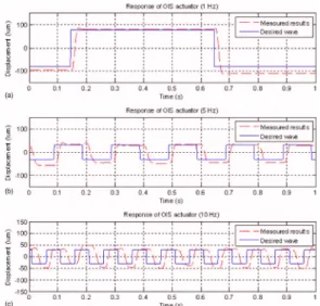
ranges of the traveling distance,ANSYSrenders larger density than the experimental counterparts and an averaged value close to that from equivalent magnetic circuit. To test the response of the actuator, experiments are conducted to mea-sure the motions of the lens holder in the proposed OIS system by a laser displacement sensor under the applied pe-riodic voltage. Figure 5 shows the measured results for square wave commands under three different driving fre-quencies: 1, 5, and 10 Hz. It is shown from this figure that the OIS is actuated by the input signal in satisfactory re-sponses. Note that the tracking performance of the OIS sys-tem could be easily improved to the error less than 0.5% if a closed-loop control scheme is applied in the future.
V. CONCLUSIONS
A novel miniaturized OIS module for a camera phone is successfully proposed, optimized, and manufactured in this study. The analysis of the magnetic field for the VCMs in the OIS is conducted by using the equivalent magnetic circuit and then verified by commercial software, ANSYS, and ex-perimental data. A good agreement with error less than 6.1% in the actuation range of the lens holder in the OIS is present. The established and verified equivalent circuit model is then successfully adopted for GA optimization to minimize the overall size of the OIS and at the same time maximizes the sensitivity of the VCM actuator under a high uniform mag-netic field. Finally, a prototype OIS system is fabricated with the dimensions resulted from the GA optimization with sat-isfactory experimental performance.
The authors would like to express special thanks to the National Science Council of Taiwan for financially support-ing this research project under NSC 96-2622-E-009-010-CC3.
1H. Kusaka, Y. Tsuchida, and T. Shimohata, “Control technology for optical image stabilization,” SMPTE J. 111, 609共2002兲.
2C.-W. Chiu, Pa. C.-P. Chao, and D.-Y. Wu, “Optimal design of magneti-cally actuated optical image stabilizer mechanism for cameras in mobile phones via genetic algorithm,”IEEE Trans. Magn.43, 2582共2007兲. 3M. Mitchell, An Introduction to Genetic Algorithms共MIT Press, 1998兲. TABLE I. GA optimization results.
No. The values to represent Design variables for GA optimum
program Constraints Optima
1 Total length of OIS lគsub 0.013艋lគsub艋0.015 0.015 2 Total wide of OIS wគsub 0.013艋wគsub艋0.015 0.015 3 Total thickness of OIS hគsub 0.008艋hគsub艋0.009 0.009 4 Total thickness of OIS T 0.000 06艋T艋0.000 42 0.042 5 The electromagnetic force Fe 0.0371艋Fe 0.011 146 6 Thickness of the yoke hគyoke 0.0008艋hគyoke艋0.001 0.000 8 7 The air gap dគyoke 0.001艋dគyoke艋0.0012 0.001 8 Length of the yoke lគyoke 0.004艋lគyoke艋0.005 0.005
FIG. 4. 共Color online兲 Comparison of the magnetic flux density between ANSYS, equivalent circuit analysis, and experimental results.
FIG. 5. 共Color online兲 Responses of the OIS system for square waves in three driving frequencies:共a兲 1, 共b兲 5, and 共c兲 10 Hz.
07F136-3 Chiu et al. J. Appl. Phys. 103, 07F136共2008兲
[This article is copyrighted as indicated in the article. Reuse of AIP content is subject to the terms at: http://scitation.aip.org/termsconditions. Downloaded to ] IP: 140.113.38.11 On: Wed, 30 Apr 2014 23:10:13