The system-on-chip design of a silicon micromachined
condenser microphone array
Mingsian R. Baia)and Shihwei Huang
Department of Mechanical Engineering, National Chiao-Tung University, 1001 Ta-Hsueh Road, Hsin-Chu 300, Taiwan, Republic of China
共Received 29 August 2003; revised 25 March 2004; accepted 30 March 2004兲
A miniature condenser microphone array that combines array signal processing and micro-electro-mechanical systems共MEMS兲 technologies is presented. A linear dynamic model and a quasistatic analysis are presented. The array configuration serves two purposes: enhancement of the signal-to-noise ratio共SNR兲 and the directivity of sensor. A least-squares beamforming design based on the template resulting from the Multiple Signals Classification algorithm is proposed to achieve a directive beam pattern. To minimize the parasitic effects on the MEMS device, a system-on-chip design composed of a microphone module, a dc bias circuit, an impedance matching circuit, and array beamforming filters is proposed in the paper. The performance of the proposed design is evaluated in terms of the frequency response, SNR improvement, and directional response through numerical simulations and experiments. © 2004 Acoustical Society of America.
关DOI: 10.1121/1.1753295兴
PACS numbers: 43.38.Bs, 43.38.Gy, 43.38.Hz, 43.38.Kb关AJZ兴 Pages: 303–312
I. INTRODUCTION
3C 共computer, communication, and consumer兲 industry has recently emerged as one of the most rapidly growing industries of modern days. Commercial products such as notebook computers, personal data assistants, mobile phones, and MP3 players are currently making their way into peo-ple’s lives. Miniaturization has been known to be one of the chief concerns of 3C products. This is particularly true for microphones that are important components of 3C products. A condenser microphone based on micro-electro-mechanical systems 共MEMS兲 technology offers a potential solution in achieving ultimate miniaturization for 3C products. Silicon microphones have received a great deal of research interest for years and an excellent review can be found in Ref. 1. However, there remain technical issues that need to be re-solved before we find widespread use of such device. Al-though conventional capacitive microphones have higher sensitivity than piezoresistive microphones, sensitivity is still a crucial consideration in micromachined capacitive phones. This sensitivity problem pertinent to silicon micro-phones is due partly to the built-in stress in the diaphragm resulting from the MEMS fabrication process, and partly to the parasitic capacitance in electrical connections. This prob-lem is further worsened by the self-noise in the chip, which may overwhelm the exceedingly weak signal generated by the device. Hence, the signal-to-noise ratio共SNR兲 has always been one of the major design factors in MEMS microphones. To address this issue of low sensitivity, a system-on-chip 共SoC兲 design of the microphone that integrates the sensor structure, a dc bias circuit, an impedance buffer, and array beamforming filters in one chip is presented in this paper. The purpose of this paper is threefold. The first purpose is to
show how electroacoustic transducers, array signal process-ing, and MEMS technology can be applied in a multidisci-plinary design problem. The second purpose is to improve SNR through integration into arrays. The third purpose is to improve directionality through integration into arrays. How-ever, for the last purpose, it shall be shown that it can be achieved above moderately high frequency due to the physi-cal constraint of array size. In the single chip design, para-sitic effects are reduced due to elimination of interconnec-tions between modules. Apart from the SoC design, a microphone array configuration is also proposed in this study to further enhance the SNR of the device. One benefit of using such array configuration is that the SNR 共in terms of power兲 increases by the number of elements in the array.2 Furthermore, the microphone array serves as a spatial filter to focus only on the source and reject unwanted noise at the other directions, making the array an attractive solution for hands-free communications. In order to achieve a highly di-rective beam pattern, a constant beamwidth array based on the template from the Multiple Signals Classification 共MUSIC兲3 algorithm is designed using the least-squares
method. For simplicity, the resulting filters are realized by analog circuits. The MEMS fabrication is well suited for such multichannel array SoC design.
In this paper, the properties of the condenser micro-phone and array filters are investigated. Electro-acoustical analogy is employed to establish a linear dynamic model of the silicon microphone, while a quasistatic analysis based on the finite difference method is conducted to find the collapse condition. Some previous research on this aspect should be mentioned. Hohm and Ku¨hnel4,5 applied an analytical ap-proach to calculate the nonlinear deflection of the diaphragm of a silicon microphone. Bergqvist6 suggested a more com-plex model based on the finite elements method 共FEM兲. Pedersen1examined the effects of the perforation in the back plate on microphone stability and performance by using the a兲Author to whom all correspondence should be addressed; electronic mail:
finite differences method 共FDM兲. Similar to the work by Pedersen and other researchers,4 – 6 electro-acoustical analogy7–9is exploited in this paper to account for the com-plex coupling among the acoustical, mechanical, and electri-cal domains. The collapse condition of the microphone is determined from a quasistatic analysis of the nonlinear sys-tem. On the basis of the linear dynamic model, performance analysis was carried out to justify the proposed MEMS mi-crophone array. As for the MEMS mimi-crophone arrays, two references are relevant to the present study. Chowdhury et al. presented a 3⫻3 MEMS capacitive microphone array.10 In their design, beamforming was accomplished by the simple delay-sum method. However, there was an error in the analy-sis of directional response, and no experimental results are presented. Another work by Arnold et al. developed a 16-element MEMS piezoresistive microphone array for wind tunnel studies.11 The fast Fourier transform is used for frequency-domain beamforming. However, instead of being fabricated on one chip, the microphones are mounted on a printed circuit board. Thus, the performance of such design was found comparable to conventional microphone arrays.
II. DESIGN OF MEMS CONDENSER MICROPHONE ARRAY
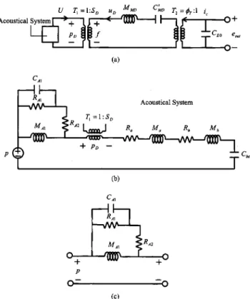
Consider a four-channel MEMS microphone array shown in Fig. 1共a兲. Four condenser microphones are fabri-cated with equal spacing on a straight line. In this section, the quasistatic and the linear dynamic models and the array beamforming design will be presented.
A. Quasistatic analysis and linear dynamic analysis We begin with a single channel condenser microphone with a square diaphragm and a perforated backplate, as shown in Fig. 1共b兲. In the metallization process, Cr and Au are deposited using evaporation as the adhesion layer and the electrode layer, respectively. The metallization layer can be
released by a lift-off process. The metallization scheme should play a role in the diaphragm stress and the parasitic capacitance. Like traditional condenser microphones, a dc bias voltage source is needed in our MEMS microphone. To predict the large deflection of the diaphragm resulting from an excessive dc bias, a quasistatic analysis in Ref. 1 is re-viewed.
Assume that the backplate is rigid and the deflection is small so that the linear model applies. For simplicity, nonlin-ear stiffening that may affect the prediction of the electro-static collapse point is not considered in the following pre-sentation. The equation of motion for the diaphragm is given as12 C11 4w d x4 ⫹2共C12⫹2C44兲 4w d x2y2⫹C11 4w d y4 ⫽12 hd3
冋
psp⫹pel⫹dhd冉
2w d x2 ⫹ 2w d y2冊
册
, 共1兲where hdis the plate thickness,d is the built-in stress, and
wd(x,y ) is the deflection. C11⫽C22, C12⫽C21, and C44are
material constants of the plate. For isotropic materials, the forgoing material constants are given by
C11⫽ E 1⫺2, C12⫽ E 1⫺2, C44⫽ E 2共1⫹兲, 共2兲 where E andare the Young’s modulus and Poisson’s ratio, respectively. In Eq. 共1兲, pspis the sound pressure, pel
repre-sents the electrostatic force per unit area due to the dc bias between the diaphragm and the backplate and is given by
pel共x,y兲⫽Kholes
⑀d⑀0
2共hd⫹⑀d共ha⫺wd兲兲
Vba2 , 共3兲
⑀dis the relative permittivity of the diaphragm material,⑀0is
the vacuum permittivity, ha is the distance of air gap, and
Vba is the dc bias voltage. The constant Kholesaccounts for
the effect when the backplate is perforated.1Although in a practical setting the diaphragm is fixed by a tapered and somewhat asymmetric junction, it is assumed for conve-nience that the diaphragm is clamped at the edge, i.e.,
wd共x,y兲⫽
wd共x,y兲
x ⫽0, wd共x,y兲⫽
wd共x,y兲
y ⫽0
on the boundary. An iterative quasistatic analysis based on the FDM is carried out for the partial differential equations in Eq. 共1兲. The large deflection of diaphragm and the collapse condition of the microphone is found from this analysis. The details of the procedure can be found in Ref. 1.
Next, electro-acoustical analogy1,8,9 is adopted for pre-dicting the linear dynamic behavior of the MEMS condenser microphone. The equivalent circuits of the microphone are shown in Fig. 2, wherein the acoustical, mechanical, and electrical domains are coupled through ideal transformers.
In the acoustical subsystem of Fig. 2共b兲, the radiation impedance is approximated by the analogous circuits8in Fig. 2共c兲, where RA1⫽0.4410c/Lm 2 , CA1⫽5.94Lm 3 /0c2
冑
, RA2⫽0c/Lm 2, MA1⫽80/3
冑
Lm,0is the density of air, FIG. 1. A schematic diagram of the microphone array.共a兲 The microphonearray with four MEMS condenser microphones.共b兲 Cross section of a con-denser microphone with a perforated backplate.
c is the sound speed in air, and Lmis the width of the square
diaphragm. Similar to the approach taken by Skvor,13 the effect of the air gap is modeled as equivalent resistance and mass elements in the acoustical domain: Ra
⫽(1.22b2/ha3Lm2)B and Ma⫽(0.1020b2/haLm
2
)B, where⫽1.86⫻10⫺5N s/m2at 20 °C is the dynamic viscos-ity of air, hais the distance of the air gap, and B is defined as
B⫽1 4ln
冉
0.16b2 ah2冊
⫺ 3 8⫹ ah2 0.16b2⫺ ah4 0.204b4, 共4兲 where ah is one-half of the width of the acoustical hole. Theacoustical holes are modeled by an acoustical resistor Rh
⫽12hb/b2Lm
2
and mass Mh⫽240hbah
2
/5b2Lm2, where hb
is the thickness of the backplate. The acoustical compliance of the backchamber is Cbc⫽Vbc/0c2, where Vbc is the
ef-fective volume. A transformer T1 with turn ratio 1: SD 共the
area of diaphragm兲 accounts for the coupling of the acousti-cal system and mechaniacousti-cal system.
In the mechanical subsystem, the flexural rigidity of the diaphragm is predominantly due to the built-in stress ac-quired during MEMS fabrication. That renders the compli-ance of the diaphragm5 CM D⫽32/6dhdLm
2
, where d is
the built-in stress and hd is the thickness of the diaphragm.
The mechanical mass of the diaphragm is given as MM D
⫽dhdLm
2
, with d being the density of the diaphragm
ma-terial. The mechanical-electrical coupling factor T
⫽CE0/CE M, where CE0is the capacitance due to the dc bias
and is given by CE0⫽Kholes⑀b⑀d⑀0Lm
2
/(ha⑀b⑀d⫹hb⑀d
⫹hd⑀b), and CE M⫽(ha⫺wd)/Vba. Hence, the impedance
matrix for the condenser microphone can be written as
Zmic⫽
冋
ZE 1 jCE M 1 jCE M ZM册
, 共5兲where ZE and ZM are the equivalent electrical impedance
and mechanical impedance, respectively. Note that this ma-trix is symmetric, as expected for a reciprocal electro-static transducer.
B. Constant beamwidth design based on the MUSIC template
Assume that M microphones are uniformly distributed with interelement spacing d. One benefit of using arrays is the improvement of SNR that can be assessed by the array white noise gain 共WNG兲 defined as the increase of the SNR between one sensor and the output of the entire array2
G⫽ SNRarray SNRsensor
.
The array inputs 共x兲 and the output 共y兲 are given, respec-tively, by
x⫽s共t兲a⫹n,
y⫽wHx⫽s共t兲wHa⫹wHn,
where s(t) is the source signal, a
⫽关1 exp关jc(d sin/c)兴¯ exp关jc(M⫺1)d sin兴/c兴T is
called the ‘‘manifold vector’’ associated with the look angle 共with respect to the normal兲 and the center frequency c, n
is the noise vector共assumed to be wide-sense stationary un-correlated white noise with equal power n2), and w is the array coefficient vector. Hence,
SNRarray⫽E兵兩s共t兲w Ha兩2其 E兵兩wHn兩2其 ⫽ E兵兩s共t兲兩2其wHaaHw n 2wHw . Recognizing that E兵兩s共t兲兩2其 n 2 ⫽SNRsensor, we end up with G⫽w HaaHw wHw .
For example, the array WNG of a benchmark delay-sum ar-ray can be calculated by setting w⫽a/M:
G⫽共1/M
2兲aHaaHa
共1/M2兲aHa ⫽a Ha⫽M.
The physical ground to result in this desirable feature is that uncorrelated noises tend to add or cancel with equal prob-ability, while signals add in phase among the array channels. Our goal is to design a narrow beam throughout a wide range of frequency. Pattern inversion by Fast Fourier
Trans-FIG. 2. The equivalent circuit based on electro-acoustical analogy of the condenser microphone. 共a兲 Complete system composed of three coupled subsystems: the acoustical system, mechanical system, and electrical sys-tem.共b兲 Detailed circuit representation of the acoustical subsystem. 共c兲 Cir-cuit representation of the radiation impedances.
form 共FFT兲 would not work well in this case because the aperture size of the four-element MEMS microphone array is just too small to produce any meaningful directivity. The spectral leakage of the truncation effect resulting from the small aperture simply destroys the directivity.
To achieve high directivity, a beamforming design based on MUSIC3 template is adopted. In the MUSIC algorithm, the beam pattern is given as
SM U共兲⫽
1
aHPNa
, 共6兲
where the angle and the manifold vector a are as defined previously, the projection matrix PN⫽兺m⫽J⫹1
M
umum H
, J is the number of sources, and um is the mth eigenvector of the
signal correlation matrix.
The beam pattern produced by the MUSIC is known to be highly directional. However, the MUSIC is mainly in-tended for finding direction of arrival and it requires inten-sive computation in the correlation matrix and eigen-decomposition. Instead of direct implementation, we adopted a practical approach that utilizes the beam pattern resulting from MUSIC as a design template. That is, we seek the array
filters to yield a narrow beam throughout a wide frequency range, as close as possible to that generated by the MUSIC template. To this end, a MUSIC template is generated using Eq. 共6兲 with a source located at 0°, at frequency c, e.g.,
one-half of the sampling frequency fs. This template with
identical subtending angle applies to all frequencies, hence the name ‘‘constant beamwidth.’’ The vector of the MUSIC template denoted as sT⫽关SM U(1)¯SM U(Qd)兴T is created
by uniformly sampling at Qd discrete angles (⫺90°⭐1 ⭐¯⭐Qd⭐90°) the MUSIC beam pattern in Eq. 共6兲. Next,
Pw equally spaced discrete frequencies, fr(l)⫽( fs/ Pw)l (1
⭐l⭐Pw, are selected within the Nyquist frequency. Let the
filter gain at the mth element and the lth frequency be wm(l).
The array pattern at the lth frequency can be written as PT共l,兲⫽
兺
m⫽1 M wm*共l兲exp冉
j 2fr共l兲共m⫺1兲d sin c冊
. 共7兲 The symbol*denotes complex conjugate. Since we wish to match an array pattern to the MUSIC template, i.e., PT(l,)⬇SM U(), the model matching problem for aspe-cific angle can be written as
冋
1 exp冉
j2fr共l兲d sin c冊
¯ exp冉
j 2fr共l兲 共M⫺1兲d sin c冊册
冋
w1*共l兲 w2*共l兲 ] w*M共l兲册
⫽SM U共兲. 共8兲Assembling all angles, 1,...,Qd of Eq.共8兲 leads to the following matrix equation:
冤
1 exp冉
j 2fr共l兲 d sin1 c冊
¯ exp冉
j 2fr共l兲 共M⫺1兲d sin1 c冊
1 exp冉
j 2fr共l兲 d sin2 c冊
¯ exp冉
j 2fr共l兲 共M⫺1兲d sin2 c冊
] ] ] 1 exp冉
j2fr共l兲d sinQd c冊
¯ exp冉
j 2fr共l兲 共M⫺1兲d sinQd c冊
冥
冋
w1*共l兲 w2*共l兲 ] wM*共l兲册
⫽冋
SM U共1兲 SM U共2兲 ] SM U共Q d兲册
. 共9兲Let the array gain vector w(l)⫽关w1*(l)¯wM*(l)兴T, sT⫽关SM U(1)SM U(2)...SM U(Qd)兴T, and
⌽共l兲⫽
冤
1 exp冉
j 2fr共l兲d sin1 c冊
¯ exp冉
j2fr共l兲 共M⫺1兲d sin1 c冊
1 exp冉
j 2fr共l兲d sin2 c冊
¯ exp冉
j2fr共l兲 共M⫺1兲d sin2 c冊
] ] ] 1 exp冉
j 2fr共l兲 d sinM c冊
¯ exp冉
j 2fr共l兲 共M⫺1兲d sinM c冊
冥
. 共10兲The optimization problem can be written as a model match-ing problem
min w共k兲
⫽储sT⫺⌽共l兲w共l兲储2, 共11兲
where we choose the two norm储•储2as the measure of match.
In general,⌽(l) is not square and Qd⬎M. This
‘‘overdeter-mined’’ problem has the least-squares solution, wLS(l) ⫽(⌽H⌽)⫺1⌽Hs
often yields impractical solutions because ⌽(l) usually has very small singular values. Alternatively, Tikhonov regularization14 is employed to solve this problem,
wLS共l兲⫽共⌽H⌽⫹I兲⫺1⌽HsT. 共12兲
By varying the parameter , we can control the degree of regularization. Repeating the same procedure for Pw
fre-quencies, the frequency response samples of the mth channel wm*(l) can be obtained. To ensure real impulse responses, the following symmetry of frequency response must be applied
Hm共0兲⫽wm*共l兲,
Hm共l兲⫽wm*共l兲, l⫽1,2,...,Pw, 共13兲
Hm共l兲⫽wm共l兲, l⫽共Pw⫹1兲,共Pw⫹2兲,...,共2Pw⫺1兲.
The impulse response for each channel is then calculated with the aid of inverse FFT,
hm共k兲⫽ 1 2 Pw
兺
l⫽0 2 Pw⫺1 Hm共l兲ej共/Pw兲lk, k⫽0,1,...,共2Pw⫺1兲. 共14兲The resulting hm(k) is generally noncausal and circular shift
is required to obtain a causal impulse response hm
⬘
(k). Since we wished to simplify the array design on the chip, we chose simple implementation using analog filters. The frequency responses of the FIR filters hm⬘
(k) are calcu-lated Hm⬘
共l兲⫽兺
k⫽0 2 Pw⫺1 hm⬘
共k兲e⫺ j共/Pw兲lk, l⫽0,1,...,共2P w⫺1兲. 共15兲 The transfer functions of the analog filters are fitted with the MATLAB15command invfreqs. The resulting analog filters of array beamforming are realized by using active filter tech-niques such as the biquad circuits.16C. Discussion of self-noise
The self-noise, or background noise, is defined as the rms output signal of the microphone in the absence of acoustical excitation. An in-depth comparison of the back-ground noise in piezoresistive, eletret condenser, and ceramic microphones can be found in the paper by Zuckerwar et al.17 Their analysis identified four types of background sources: 共1兲 mechanical Johnson noise due to the Brownian motion
of air molecules impinging on the diaphragm, as repre-sented by a damping resistor RA, and 1/f 共inversely pro-portional to frequency兲 noise generated by motion of the diaphragm;
共2兲 thermal channel noise generated in the FET channel; 共3兲 gate shot noise generated in the FET;
共4兲 electrical Johnson noise generated in the drain resistor Rd.
An equivalent circuit analysis in their work led to the follow-ing expression of the power spectral density of background noise in terms of the above-mentioned sources:
J⫽ S 2共4kT R A⫹Am 2 / f兲 共1⫺2/ 0 2兲2⫹共/ 0Q兲 2⫹
冋
4共0.65兲kT gm ⫹ 2qIG 共Ct0兲2册
共gmRd兲2⫹4kTRd. 共16兲In Eq.共16兲, S is the diaphragm area, k is the Boltzmann constant, T is the absolute temperature, f andare frequen-cies in Hz and rad/s, respectively, 0 and Q are the
reso-nance and quality factor of the diaphragm, Am2 is the 1/f coefficient, gm is the FET transconductance, Ct0 is the
diaphragm-backplate capacitance, q is the electronic charge, and IG is the gate leakage current. As revealed in Eq.共16兲,
the gate shot noise introduces a 1/2component. At frequen-cies well below the resonance, the membrane damping 共Brownian兲 component behaves as a Johnson noise source, which dominates over the channel and drain resistor compo-nents.
An important finding in their work is a formula obtained by linear regression that correlates the 1/f noise coefficient (b1) with the diaphragm damping resistor RA.
log共b1兲⫽⫺24.1⫹1.89 log共RA兲. 共17兲
This empirical relationship applies to any diaphragm-based microphone, independent of detection technology. Because the diaphragm damping resistance increases inversely with diaphragm diameter, one may expect a significant 1/f com-ponent in MEMS microphones. As a caveat, the SNR of a microphone with overly damped diaphragm can be quite poor at low frequencies due to the associated 1/f noise.
III. NUMERICAL AND EXPERIMENTAL INVESTIGATIONS
A. Quasistatic analysis
Following the aforementioned iterative procedure of FDM, the quasistatic analysis was carried out to predict the collapse condition. Table I shows the parameters assumed in this simulation. The diaphragm material was assumed to be silicon nitride. The FDM calculation was based on a mesh with 25⫻25 grid points, covering a quarter of the diaphragm. The built-in stress⫽50 MPa and the Young’s modulus⫽300 GPa is assumed for a 1 mm square diaphragm made of sili-TABLE I. The parameters assumed in the FDM procedure for the quasistatic analysis of the MEMS condenser microphone.
Diaphragm material Silicon nitride
Diaphragm length (Lm) 1 mm
Diaphragm thickness (hd) 1m
Air gap distance (ha) 3m
Acoustical holes number (Nm) 100
Acoustical holes side length (ad) 60m
Vacuum permittivity (e0) 8.85⫻10⫺12F/m Dielectric constant of the diaphragm (ed) 7
Young’s modulus共E兲 300 GPa
Built-in stress (d) 50 MPa
Poisson’s ratio共兲 0.2
Bias voltage (Vba) 50 V
con nitride.18The calculated deflection profiles for three dif-ferent conditions including ‘‘bending effect only,’’ ‘‘built-in stress only,’’ and ‘‘stress⫹bending’’ are shown in Fig. 3. The results indicate that the effect due to built-in stress is the dominant factor in overall diaphragm stiffness 共about two orders higher than the bending effect兲. If only the built-in stress is considered, the maximum deflection at the center of the diaphragm reaches 7 nm, which is of the same order as the value 3.3 nm predicted by a parallel plate/linear spring model with the spring constant deduced from CM D
⫽32/6
dhdLm
2
. Using this FDM model, the critical bias voltage near collapse was found to be 84 V for the present setting. For stability of the device, a conservative value, 60% of the previously calculated critical voltage, or 50 V, was thus selected to be the dc bias. The maximum static deflec-tion of the diaphragm corresponding to such dc bias voltage attained 0.32 m. Since the predicted deflection is far less
than the nominal air gap 共3m兲, the condenser microphone should be rather safe during operation without the risk of collapse.
B. Simulation of linear dynamic model and preamplifier circuits
The linear dynamic model is simulated with the aid of thePSPICE.19Table II summarizes the parameters assumed in this simulation. For simplicity, the linear analysis considers only the dynamic response, but not the dc deflection of the diaphragm caused by the bias voltage. The partial pull-down may change the effective compliance, increasing it or de-creasing it depending on the proximity to snap-down. In-creasing共decreasing兲 the compliance reduces the bandwidth 共responsivity兲. Figure 4 shows the simulated frequency re-sponse between the incident sound pressure and the open-circuit output voltage of the microphone with a 1 mm⫻1 mm
FIG. 3. The deflection profiles calculated by the FDM for three different conditions: bending effect only, built-in stress only, and ‘‘stress⫹bending.’’ The diaphragm material was assumed to be silicon nitride. The built-in stress⫽50 MPa, the Young’s modulus⫽300 GPa, and the diaphragm is sub-ject to a uniform load of 5 Pa.
FIG. 4. The frequency response of the MEMS condenser microphone simu-lated by using the PSPICE. The effects of parasitic capacitance on sensitiv-ity are also indicated in the same plot. In the simulation, 10 pF parasitic capacitance is assumed.
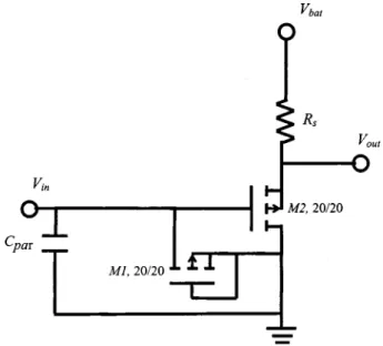
FIG. 5. The PMOS source-follower preamplifier. Two PMOS transistors of 20m/20m are selected to implement the amplifier.
TABLE II. The parameters assumed in the linear dynamic analysis of the MEMS condenser microphone.
Diaphragm material Silicon nitride Diaphragm length (Lm) 1 mm
Diaphragm thickness (hd) 1m
Diaphragm density (d) 3440 kg/m3
Backplate thickness (hb) 20m
Air gap distance (ha) 3m
Air density (0) 1.3 kg/m3
Sound speed共c兲 343 m/s
Dynamic viscosity of air共兲 1.86⫻10⫺5N s/m2
Acoustical holes number (Nm) 100
Acoustical holes side length (ad) 60m
Vacuum permittivity (e0) 8.85⫻10⫺12F/m
Dielectric constant of the diaphragm (ed) 2
Dielectric constant of the back plate (eb) 2
Young’s modulus共E兲 300 GPa Built-in stress (d) 50 MPa
Poisson’s ratio共兲 0.2 Bias voltage (Vba) 50 V
square diaphragm. The 3 dB cut-off frequency occurs at 42.7 kHz. The frequency response is relatively flat throughout the band 0– 42 kHz. The predicted open-circuit sensitivity was approximately ⫺39.7 dB V/Pa, or 10.35 mV/Pa. The ob-tained sensitivity of MEMS microphone is comparable to conventional 1/4 in. condenser microphones.
The preamplifier shown in Fig. 5 is needed because of the relatively large output impedance of the condenser mi-crophone. This buffering preamplifier utilizes the PMOS transistor as the bias element, owing to its high impedance characteristic. The optimum SNR is achieved by having much higher input impedance than the sensor impedance. After the preamplifier, the signal should be robust and can be taken off chip if necessary. However, on-chip integration of the buffering preamplifier is still important to reduce parasit-ics. Figure 4 also plots the microphone frequency response if the parasitic capacitance Cpar⫽10 pF is present. The loss of
sensitivity is frequency dependent. The sensitivity of MEMS
microphones is significantly reduced by 10 dB up to the cutoff frequency due to the parasitic capacitance. As evident from this result, the SoC design is crucial for MEMS micro-phones to yield sufficient sensitivity.
C. Constant beamwidth design based on the MUSIC template
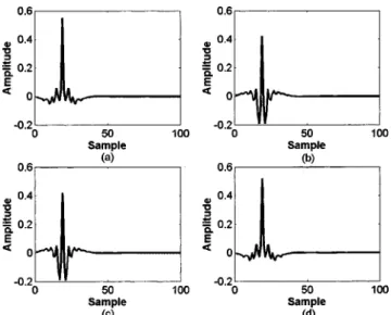
In this section, the constant beamwidth design based on the MUSIC template is presented. The array contains four microphones in a line, with interelement spacing 5 mm. A MUSIC template is constructed using Eq. 共6兲 for Qd⫽181 discrete angles and Pw⫽256 discrete frequencies. The beam pattern of the resulting template is shown in Fig. 6. This is the MUSIC spectrum plotted in the angle space, and not the conventional Fourier spectrum. This template exhibits a sharp peak at 0° with beamwidth approximately 10° for 40 dB attenuation. After obtaining the frequency response of the microphone array, the impulse response, or the FIR filter coefficients, are calculated using inverse FFT. Circular shift is applied to obtain causal FIR filters. The resulting impulse responses of the array FIR filters are shown in Fig. 7. The MATLABfunction invfreqs is used to find the continuous time
FIG. 6. A template obtained using MUSIC algorithm for Qd⫽181, Pw
⫽256. The beam pattern of this template exhibits a sharp peak at 0° with beamwidth approximately 10° for 40 dB attenuation.
FIG. 7. The calculated impulse responses of the array FIR filters after the circular shift. 共a兲 Channel one. 共b兲 Channel two. 共c兲 Channel three. 共d兲 Channel four.
FIG. 8. Analog implementation of the array filters.共a兲 Four channel micro-phone array implemented by the biquad modules.共b兲 Detailed biquad cir-cuit.
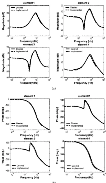
transfer functions of the array filters, applicable to the fre-quency range 0– 8 kHz. Next, these array filters are imple-mented by using analog biquad circuits. Since each analog transfer function is of order four, two biquad circuits shown in Fig. 8 are cascaded to realize the array filter. The param-eters of the biquad circuits are shown in Table III. The fre-quency responses obtained using the simulation and the ex-periment, respectively, are compared in Fig. 9. The equivalent filter weights at four frequencies are shown in Table IV. The magnitude and phase responses are in good agreement. It is worth noting that the 180° phase inversion at 6 kHz for elements 2 and 3 results in the increased directiv-ity.
D. Experimental investigation
In order to verify the proposed array microphone sys-tem, experiments were carried out using a commercial prod-uct of silicon condenser microphone, SP0103NC3-2 of EMKAY. This omni-directional microphone has the fre-quency range of 100 Hz–10 kHz and sensitivity of ⫺42 dB V/Pa at 1 kHz. With the same configuration as in the simu-lation, a linear array comprising four elements of such mi-crophones with 5 mm interelement spacing was constructed, as shown in Fig. 10. The previously designed array filters for these four microphone elements were realized by using op-erational amplifier circuit. Using this experimental arrange-ment, tests were conducted inside an anechoic chamber to evaluate the SNR as well as the directivity for various mi-crophone configurations.
First experiment compares the SNRs of one single mi-crophone and the four-element array. In each case, the SNR is calculated by subtracting the power of the sensor output when the microphones are exposed to a white noise input band-limited to 20 kHz, from the power of the sensor output
when the source is switched off. Hence, the noise would be the combination of the electronic self-noise and the back-ground noise inside the anechoic chamber. The thus mea-sured SNRs were found to be 24.1 and 35.5 dB for the single microphone and the array microphone, respectively. The SNR was improved by 11.4 dB, which was not far from the theoretical prediction, 12 dB. This experimental result sug-gests that array configuration is capable of enhancing SNR, as compared to one sensor element. However, the broadband measurement does not assess the performance at 6 kHz.
A second experiment compares the measured directional responses of the silicon microphones for three cases. The results are shown in Fig. 11. The first case labeled in Fig. 11共a兲 as ‘‘one microphone’’ refers to the measured directivity of a single microphone. The second case labeled in Fig. 11共b兲 as ‘‘four microphones’’ refers to the measured directiv-ity produced by the direct sum of four microphone outputs. The third case labeled in Fig. 11共c兲 as ‘‘four microphones with filters’’ refers to the measured directivity produced by TABLE III. The parameters used in the analog biquad circuits of the array
filters.
Module 1 Module 2 Module 3 Module 4
R2 2.65⫻103⍀ 3.64⫻103⍀ 1.75⫻103⍀ 5.60⫻103⍀ R4 8.31⫻102⍀ 7.68⫻103⍀ 7.89⫻102⍀ 1.07⫻104⍀ R5 Infinite 3.44⫻103⍀ Infinite 3.18⫻103⍀ R6 Infinite 4.34⫻103⍀ Infinite 2.83⫻104⍀ R7 7.87⫻102⍀ 2.22⫻104⍀ 2.75⫻102⍀ 1.74⫻104⍀ RC 6.82⫻103⍀ 2.39⫻103⍀ 9.75⫻103⍀ 5.25⫻103⍀ RD 1.17⫻103⍀ 1.72⫻103⍀ 1.11⫻103⍀ 1.24⫻103⍀ r2 10.0⫻103⍀ 10.0⫻103⍀ 10.0⫻103⍀ 10.0⫻103⍀ C1 0.01F 0.01F 0.01F 0.01F C2 0.01F 0.01F 0.01F 0.01F Module 5 Module 6 Module 7 Module 8
R2 2.26⫻103⍀ 5.52⫻103⍀ 1.64⫻103⍀ 3.82⫻103⍀ R4 7.88⫻102⍀ 8.59⫻103⍀ 8.15⫻102⍀ 1.32⫻104⍀ R5 Infinite 3.42⫻103⍀ Infinite 2.78⫻103⍀ R6 Infinite 2.19⫻104⍀ Infinite 7.71⫻103⍀ R7 4.26⫻102⍀ 1.99⫻104⍀ 2.76⫻102⍀ 7.18⫻104⍀ RC 6.83⫻103⍀ 4.20⫻103⍀ 1.63⫻104⍀ 4.15⫻103⍀ RD 1.17⫻103⍀ 1.31⫻103⍀ 1.07⫻103⍀ 1.32⫻103⍀ r2 10.0⫻103⍀ 10.0⫻103⍀ 10.0⫻103⍀ 10.0⫻103⍀ C1 0.01F 0.01F 0.01F 0.01F C2 0.01F 0.01F 0.01F 0.01F
FIG. 9. Comparison of the frequency responses of the analog array filters obtained using the simulation and the experiment, respectively.共a兲 Magni-tude response.共b兲 Phase response.
filtering the four microphone outputs with the aforemen-tioned analog filter circuits. Comparison of the experimental results of cases 1 and 2 reveals that only minor improvement on directivity is obtained if the array outputs are directly summed. However, significant improvement on directivity is observed by comparing cases 1 and 3 if the array outputs are preprocessed by the previously designed constant beam-width array filters. Specifically, at the frequency 6 kHz, deep notches appear at the end-fire direction and the 10 dB beam-width reaches approximately ⫾60° when the four micro-phone outputs are filtered with the aforementioned analog filter circuits. This is also revealed in the measured directiv-ity indices at four frequencies in Table IV: 0.533 dB for the delay-sum array versus 1.997 for the MUSIC array at 6 kHz.
IV. CONCLUSIONS AND FUTURE PERSPECTIVES The present work represents a multidisciplinary effort that combines the knowledge in electroacoustic transducers,
array signal processing, and MEMS technology. The original contribution of this paper can be summarized as follows. First, by taking advantage of MEMS process, we have ac-TABLE IV. The equivalent filter weights and directivity indices at four
frequencies.
Frequency
共Hz兲 Element
Weights Directivity index共dB兲 Magnitude
共dB兲
Phase
共degree兲 Delay Sum MUSIC 1 0.678 36 ⫺15.87 500 2 1.586 ⫺13.619 0.004 0.004 3 1.352 ⫺13.576 4 0.475 28 ⫺15.285 1 2.498 5 ⫺27.868 1000 2 0.602 49 ⫺24.254 0.015 0.016 3 0.360 99 ⫺24.558 4 1.260 2 ⫺31.171 1 5.659 4 ⫺52.9 2000 2 ⫺4.723 8 ⫺44.433 0.060 0.087 3 ⫺5.925 4 ⫺43.677 4 4.780 6 ⫺58.882 1 17.578 ⫺194.06 6000 2 12.482 ⫺14.345 0.533 1.997 3 12.652 ⫺14.392 4 17.859 ⫺202.77
FIG. 10. Experimental arrangement of the four-element MEMS microphone array.
FIG. 11. Comparison of the measured directional responses of the silicon microphones.共a兲 The measured directivity of a single microphone. 共b兲 The measured directivity produced by the direct sum of four microphone out-puts.共c兲 The measured directivity produced by filtering the four microphone outputs with the analog filter circuits.
complished a system design which attempts to integrate a microphone array and the associated circuit on one chip. This differs from common approaches of microphone arrays that are predominantly based on single channel conventional mi-crophones. Second, a beamforming technique more sophisti-cated than simple delay-sum method was developed in this study to improve the SNR and directionality. A least-squares model match procedure is proposed in the synthesis of the array filters to modify a DOA algorithm into a practical beamforming method. Third, in addition to the array beam-forming design, the proposed idea was actually implemented and verified through experiments. The array filters are based on analog implementation that avoids the complexity of digi-tal implementation.
Apart from the work accomplished in this study, certain limitations concerning the proposed system should be men-tioned. Although the SNR is improved using the array con-figuration, little directivity is seen in the results of the array for frequencies below 5 kHz, which is the range for human speech. To further enhance the array directivity, a number of solutions are planned for the future research. The array con-figuration adopted in the present study is the so-called ‘‘di-mensional array.’’20Directivity of such arrays is frequency-dependent and proportional to the aperture size of the array. Under the physical constraint of the small aperture of the present MEMS microphone, instead of the present analog implementation, high directivity can possibly be attained by using direct digital implementation of the beamforming al-gorithms. Yet, another possibility is using the so-called dif-ferential array.20 In contrast to the dimensional arrays, the directivity of differential arrays is independent of frequency and aperture size. However, the price to pay using this ap-proach is that its frequency response hasn共: frequency, n: element number ⫺1兲 dependence. This is a characteristic with differential arrays—higher directivity but lower array WNG, and hence lower dynamic range. This suggests that equalization is required to boost the gain at the low frequen-cies, while suppressing the noise amplification at the high frequencies. This could be quite challenging for a MEMS device since the SNR is generally a crucial problem at low frequencies due to the previously mentioned 1/f noise com-ponent. The issue of whether both attributes—SNR improve-ment and good directivity in terms of array configurations— can be best compromised will be addressed in future research.
ACKNOWLEDGMENTS
The work was supported by the Nation Science Council in Taiwan, Republic of China, under Project No. NSC 91-2212-E009-032. The authors also wish to thank Knowles Electronics, Inc. for free samples of the MEMS micro-phones.
1M. Pedersen, ‘‘A polymer condenser microphone realized on silicon con-taining preprocessed integrated circuits,’’ Ph.D. dissertation, University of Twente, The Netherlands, 1997.
2H. L. Van Trees, Optimal Array Processing共Wiley, New York, 2002兲. 3R. O. Schmidt, ‘‘Multiple emitter location and signal parameter
estima-tion,’’ IEEE Trans. Antennas Propag. AP-34, 276 –280共1986兲.
4D. Hohm and G. Hess, ‘‘A subminiature condenser microphone with sili-con nitride membrane and silisili-con back plate,’’ J. Acoust. Soc. Am. 85, 476 – 480共1989兲.
5W. Ku¨hnel and G. Hess, ‘‘A silicon condenser microphone with structured back plate and silicon nitride membrane,’’ Sens. Actuators, A 30, 251–258 共1992兲.
6
J. Bergqvist, ‘‘Finite element modeling and characterization of a silicon condenser microphone with a highly perforated back plate,’’ Sens. Actua-tors, A 39, 191–200共1993兲.
7H. F. Olson, Acoustical Engineering共Van Nostrand, Princeton, NJ, 1957兲. 8
L. L. Beranek, Acoustics共McGraw–Hill, New York, 1954兲.
9M. Pedersen, W. Olthuis, and P. Bergveld, ‘‘High-performance condenser microphone with fully integrated CMOS amplifier and DC-DC voltage converter,’’ J. Microelectromech. Syst. 7, 387–394共1998兲.
10
S. Chowdhury, M. Ahmadi, G. A. Jullien, and W. C. Miller, ‘‘A MEMS Implementation of an Acoustical Sensor Array,’’ Proceedings of the IEEE International Symposium on Circuits and Systems共ISCAS 2001兲, Sydney, Australia, 2 May, 2001, pp. 273–276.
11D. P. Arnold, T. Nishida, L. N. Cattafesta, and M. Sheplak, ‘‘A directional acoustic array using silicon micromachined piezoresistive microphones,’’ J. Acoust. Soc. Am. 113, 289–298共2003兲.
12S. P. Timoshenko and S. Woinowsky-Krieger, Theory of Plates and Shells 共McGraw–Hill, New York, 1959兲.
13
Z. Skvor, ‘‘On the acoustical resistance due to viscous losses in the air gap of electrostatic transducers,’’ Acoustica 19, 295–299共1968兲.
14A. Schuhmacher, J. Hald, K. B. Rasmussen, and P. C. Hansen, ‘‘Sound source reconstruction using inverse boundary element calculations,’’ J. Acoust. Soc. Am. 113, 114 –127共2003兲.
15
A. Grace, A. J. Laub, J. N. Little, and C. M. Thompson, Matlab Control
System Toolbox共The Math Works, Natick, MA, 1999兲.
16W. K. Chen, Passive and Active Filters: Theory and Implementations 共Wiley, New York, 1986兲.
17A. J. Zuckerwar, T. R. Kuhn, and R. M. Serbyn, ‘‘Background noise in piezoresistive, electret condenser, and ceramic microphones,’’ J. Acoust. Soc. Am. 113, 3179–3187共2003兲.
18M. Madou, Fundamentals of Microfabrication 共CRC Press, New York, 1997兲.
19
OrCad, PSPICE, Mixed A/D Circuit Simulator共Cadence Design Systems,
San Jose, CA, 2002兲.
20G. M. Sessler and J. H. West, ‘‘Directional Transducers,’’ IEEE Trans. Audio Electroacoust. AU-19, 19–23共1971兲.