Design example: From Table IV of Reference 4 for a 12-element array (llth-order Zolotarev polynomial), with a speci-fied sidelobe level of 27-71 dB (in the terminology of Reference 4, a large amplitude ripple of 24-29549), the optimum element excitations are given here in Table 1, and the corresponding
60 90
Fig. 1 Radiation pattern of a 12-element Zolotarev array with 27-71 dB
sidelobe levels
Table 1 EXCITATIONS FOR OPTIMUM 12-ELEMENT ARRAY
Excitation
Value (unnormalised) obtained directly
from Reference 4 Value (normalised) 2-239697 5-918025 7-597763 7026568 4-918025 2-810892 0-294784 0-778917 1000000 0-924821 0-647299 0-369963 array pattern is shown in Figure 1. Note that the sidelobes are of uniform height at the correct design value. This represents an improvement on results obtained by discretisation of the continuous Bayliss distribution.5
Conclusions: An exact method for optimum difference pattern synthesis of linear arrays, corresponding to that of the Dolph-Chebyshev method for optimum sum patterns, has been demonstrated. A complete investigation is nearing completion and a more comprehensive paper, giving methods of comput-ing element excitations, sidelobe levels, difference lobe beam-widths and boresight slope, will be published in the near future.
D. A. McNAMARA 18th June 1985
CSIR PO Box 395
Pretoria, 0001 South Africa References
1 DOLPH, c. L.: 'A current distribution for broadside arrays which optimises the relationship between beamwidth and side-lobe level',
Proc. Inst. Radio Engrs., 1946, 34, pp. 335-348
2 PRICE, o. R., and HYNEMAN, R. F. : 'Distribution functions for mono-pulse antenna difference patterns', IRE Trans., 1960, AP-8, pp. 567-576
3 LEVY, R.: 'Generalised rational function approximation in finite intervals using Zolotarev functions', IEEE Trans., 1970, MTT-18, pp. 1052-1064
4 LEVY, R. : 'Characteristics and element values of equally terminated Achieser-Zolotarev quasi-low-pass filters', ibid., 1971, CT-18, pp. 538-544
5 ELLIOTT, R. s.: 'Antenna theory and design' (Prentice Hall, Engle-wood Cliffs, NJ, 1981)
SYSTOLIC ENCODER FOR FAST WAVEFORM VECTOR QUANTISATION
Indexing term: Codes
The letter presents a systolic architecture that can efficiently perform the encoding operations of waveform vector quanti-sation using the squared-error distortion measure. In the system, squared-error cells and comparing cells are used to achieve modularity and concurrency. An index offset approach is employed for reducing I/O pins.
Introduction: Vector quantisation is a rather attractive approach to achieve both low bit rate and high quality in speech and image waveform coding.12 A (waveform) vector quantiser is a system that maps a K-dimensional input (waveform) vector into an M-dimensional vector suitable for communication over a digital channel or storage in memory. It consists of a codebook of possible codewords (reproduction vectors) and a minimum encoding rule. Structurally a vector quantiser can be decomposed into one encoder and one decoder.
Let K be the dimension of the input vector X and the codeword X, N be the number of codewords, C = {Xh i = 1,
2, ..., N} be the codebook and d(X; X) be the cost or distor-tion measure for mapping a vector X into X. Since minimising the squared error is the most common criterion for waveform vector quantisation,2 the distortion measure between the ;th input vector Xi = [x] xj ... xf] and the ith codeword X{ =
[c,1 cf ... cf\ is defined as follows:
d(Xy, Xt) = £ (x° - c?)2 n = l
(1)
With such a minimum distortion mapping, operations of the encoder can be partitioned into two parts: (i) computing d(X; J?,) for i = 1, 2, ..., N, where i is a codeword index; (ii) selecting the value of i for which d(X; X^ is minimised. Oper-ations of the decoder are simply to look up the codeword indexed by the encoder from the stored codebook. Clearly, the encoder involves more complicated operations than the decoder.
Hence, to improve the processing speed of a waveform vector quantiser, fast processors for the encoder are necessary. Although the systolic primitive recogniser with 50% efficiency described by Liu and Fu3 can be used for this task, it usually requires many I/O pins in realisation. In this letter a systolic architecture based on an index offset approach for the encoder is proposed to alleviate the I/O pin problem. Besides, we also describe how to make the proposed encoder possess 100% instead of 50% efficiency. As described by Kung,4 a systolic system is particularly suitable for VLSI implementation and gains considerable speed improvement over a Von-Neumann one.
Systolic encoder: The data flow used in the proposed system is similar to that for primitive recognition described by Liu and Fu,3 with the difference that in the proposed system the feeding of identifier (codeword index) streams, which may require many I/O pins, is removed (see Fig. 1). The input vector streams and the codeword streams move through the array in opposite directions. The former is delayed for N — 1 cycle periods (shown by one '*') to let the 1st input vector meet the 1st codeword at the 1st row. The latter should recir-culate continuously in order to process streams of input vectors. Also, adjacent data in these two must be separated by one cycle period (shown by one 0), otherwise some input vectors and some codewords will just pass by instead of meeting each other.
In Fig. 1, a distortion calculator comprising K x N squared-error cells is used for the distortion computation. Each row of it realises eqn. 1 for the coming input vector and the coming codeword. Each squared-error cell evaluates a spe-cific term of the summation over n in eqn. 1. All the oper-ations are pipelined in such a way that each cell is doing part of the computation and passes the data and the results to the neighbouring cells. An index selector composed of N
ing cells, one modulo-N counter and one adder is used for the index selection. Each comparing cell compares the current distortion value coming from the left with the computed minimum-distortion value from the above, and passes the smaller one along with its identifier to the lower cell. Note that the identifier of the current distortion value coming from the ith row (simply called the ith current identifier) is assigned with index i and stored in the corresponding cell, as shown in Fig. 1.
We can see from the above and Fig. 1 that the N compari-sons between a given input vector and the N codewords are started at the 1st row and ended at the iVth row. The sequence of codewords in comparison with the 1st input vector is 1, 2, ..., N, with the 2nd one 2, 3, ..., N, 1, and so forth. Since the current identifiers used in the N comparing cells are fixed in the sequence 1, 2,..., N, the resulting identifier obtained from the Nth comparing cell must be offset properly to correctly encode the input vectors. With little effort, we can find that offset value 0 is required for the 1st input vector, offset value 1 is required for the 2nd one, and so forth. Note that, when
comparing cell squarec cell X \ a
-•-t
y -error Vf
— a'!
uTT
a ' - • - a* (x - u ) v - • - u ( i ) if b < c then z—-b else ( i i )offsetting the identifier, mod-N addition is required. Since N is usually a power of 2 in most applications, we simply use a log2 N-bit adder for this operation. Besides, one mod-N counter is enough to provide all possible offset values due to the recirculating nature of the N codewords.
Since the encoding operations are pipelined and the data streams are separated by one cycle period, the encoding results will come out at a rate of one per two cycles after some initial delay, and the mod-JV counter should be triggered by half of the clock. Also, it must be properly initialised to provide the offset value in such a manner as described above.
The complete architecture of the proposed system for K = 3 and N — 4 is shown in Fig. 2. Two buffers and two delay
buffer
D = delay element
the removed identifier streams
( i n )
Fig. 1 Dataflow of proposed system
Fig. 2 Proposed architecture for K = 3 and N = 4
wedges are used for the data flow. The clock rate of 0j used for the buffers is K times that of $2, which is used in the other parts of the system except for the mod-N counter. The mod-N counter is triggered by 02/2 and initialised by 3 in the present case. When the input (codeword) buffer is filled with K samples, one input vector (codeword) is generated and loaded into the next stages. The loading operations are assumed fast enough so that the samples can come in continuously. We can see from Fig. 2 that it takes K + N + 1 cycle periods of <p2 for
the encoder to encode one given input vector. However, for a stream of inputs, a new encoding result will come out every two cycles.
Discussion: In the proposed system, if the interspersed zero vectors are replaced with codewords and some other input vectors properly, as shown in Fig. 2, its efficiency will become 100% rather than 50%. Besides, for further improving the throughput, it is worthwhile to pipeline the operations in each squared-error cell.
Owing to the use of the index offset approach, there is no need to feed index streams to the system. Hence I/O pin requirements of the proposed system are greatly reduced when compared with those of the primitive recogniser described in Reference 3. To make the system more modular, the hardware for offset indices containing one mod-N counter and one adder can be moved to the decoder or the next processing stage in applications.
As described in this letter, our proposed encoder is in fact a vector pattern matcher. Systems based on the absolute-value distortion measure, which may be popular in other applica-tions, can be achieved simply by altering the functions of the squared-error cell. Hence, besides for waveform vector
sation, it can be used in many other applications, such as primitive recognition.
CHIN-LIANG WANG 10th June 1985 CHE-HO WEI
SIN-HORNG CHEN*
Institute of Electronics
Institute of Communication Engineering* National Chiao Tung University Hsin-Chu, Taiwan, Republic of China
References
1 GERSHO, A., and CUPERMAN, v.: 'Vector quantisation: a pattern-matching technique for speech coding', IEEE Commun. Mag., Dec. 1983, pp. 15-21
2 GRAY, R. M. : 'Vector quantization', IEEE Acoust., Speech & Signal Process. Mag., Apr. 1984, pp. 4-29
3 LIU, H. H., and FU, K. S. : 'A VLSI systolic processor for fast seismic signal classification'. Proceedings of 1983 international symposium on VLSI technology, system and applications, Taipei, Taiwan, 1983, pp. 240-244
4 KUNG, H. T.: 'Why systolic architecture', Computer, 1982, 15, pp. 37-46
2-18 GHz DISTRIBUTED AMPLIFIER IN HYBRID FORM
Indexing terms: Microwave devices and components, Micro-wave amplifiers
Practical results for a four-stage hybrid distributed amplifier built on 25-4 mm-square alumina substrate using Avantek AT10600 MESFETs are presented. The power gain is (4-5 ± 1-5) dB from 2 to 18 GHz with input and output return loss of better than 10 dB. The noise figure across that band is better than 6-3 dB.
Very wideband distributed amplifiers in monolithic form have been presented.1-2 Building distributed amplifiers in hybrid form has the advantages of ease of construction and freedom of choice of MESFET used. The performance of the distrib-uted amplifier is mostly determined by the characteristic of the MESFET selected. Factors limiting the bandwidth and gain flatness of the distributed amplifier were analysed, and the results used to select a suitable commercially available MESFET.
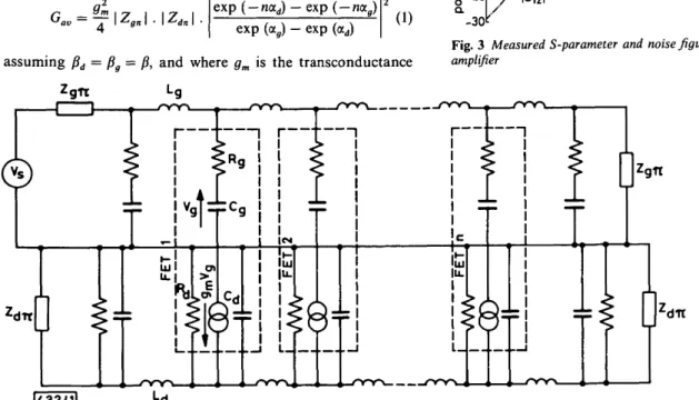
The available gain of a distributed amplifier with lossy FETs as shown in Fig. 1 can be shown to be
av
=
d-f\z
gn\.\z
dn\.
exp (-n<xd) - exp (-Ma )
exp (a ) - exp (ccd)
(1)
assuming /?d = /? = /?, and where gm is the transconductance
of the FET, Zgn is the n section characteristic impedance of
the gate line, Zdn is the n section characteristic impedance of
the drain line, ag is the attenuation coefficient per section of
the gate line, ad is the attenuation coefficient per section of the
drain and gate line, and n is the number of stages in the amplifier.
The frequency-dependent terms in eqn. 1 are Zgn, Zdn, ag, ad
and /?. These terms are found by deriving the ABCD matrices of a n section of the gate and drain line. A computer is used to plot their variation with frequency. Results show that the gate capacitance of the MESFET limits both the bandwidth and gain flatness of the amplifier. The input resistance /?, of the MESFET limits the gain flatness. The output resistance Rds of
the MESFET lowers the gain of the amplifier across the band-width. Thus we can summarise the equivalent circuit require-ments for the choice of MESFET as (i) low value of Cgs, (ii)
low value of Rg, (iii) high value of Rd, (iv) high value of gm and
(v) low noise figure.
A four-stage distributed amplifier is built on 25-4 mm-square alumina substrate using four AT10600 MESFET chips. The gate and drain line inductors are implemented using bond wires of 25 fim diameter. The layout of the circuit is shown in Fig. 2 and the performance of the amplifier is shown in Fig. 3. The drain of the first FET is connected to the padding
capac-via-holes loaded with silver epoxy
Fig. 2 Layout of four-stage distributed amplifier on alumina substrate 10r
&"
»
1-10 T3 O-15 c a-20 -30 noise figure__ 8 10 12 frequency, GHz 16 18Fig. 3 Measured S-parameter and noise figure of four-stage distributed amplifier
<m
1432/11
Fig. 1 Schematic diagram of equivalent circuit of n-stage distributed amplifier