Soft-mold-induced self-construction of polymer patterns under microwave irradiation
Fu-Hsiang Ko, Chia-Tien Wu, Mei-Fen Chen, Jem-Kun Chen, and Tieh-Chi Chu
Citation: Applied Physics Letters 90, 191901 (2007); doi: 10.1063/1.2737364 View online: http://dx.doi.org/10.1063/1.2737364
View Table of Contents: http://scitation.aip.org/content/aip/journal/apl/90/19?ver=pdfcov Published by the AIP Publishing
Articles you may be interested in
Super-resolution fluorescence imaging of nanoimprinted polymer patterns by selective fluorophore adsorption combined with redox switching
AIP Advances 3, 102128 (2013); 10.1063/1.4827155
Influence of gas rarefaction on the lateral resolution achievable by thermocapillary patterning Appl. Phys. Lett. 98, 063107 (2011); 10.1063/1.3551535
Hybrid mold reversal imprint for three-dimensional and selective patterning J. Vac. Sci. Technol. B 24, 2968 (2006); 10.1116/1.2366676
Polymer nanofibers by soft lithography
Appl. Phys. Lett. 87, 123109 (2005); 10.1063/1.2046731
Dynamic modeling and scaling of nanostructure formation in the lithographically induced assembly and self-construction
Appl. Phys. Lett. 82, 3200 (2003); 10.1063/1.1572963
This article is copyrighted as indicated in the article. Reuse of AIP content is subject to the terms at: http://scitation.aip.org/termsconditions. Downloaded to IP: 140.113.38.11 On: Thu, 01 May 2014 00:29:49
Soft-mold-induced self-construction of polymer patterns under microwave
irradiation
Fu-Hsiang Koa兲and Chia-Tien Wu
Institute of Nanotechnology, National Chiao Tung University, Hsinchu 300, Taiwan and Department of Materials Science and Engineering, National Chiao Tung University, Hsinchu 300, Taiwan
Mei-Fen Chen and Jem-Kun Chen
National Tsing Hua University, Hsinchu 300, Taiwan and National Taiwan University of Science and Technology, Taipei 106, Taiwan
Tieh-Chi Chu
Yuanpei University of Science and Technology, Hsinchu 300, Taiwan
共Received 17 January 2007; accepted 12 April 2007; published online 7 May 2007兲
In this study, the authors used a soft-mold-induced self-construction method to fabricate three-dimensional patterns under microwave irradiation for 1 min. The authors estimated the actual pattern growth temperature using a fluorescence probe technique. The temperature at which pattern growth originated was, by necessity, higher than the glass transition temperature of the novolak resist. Electrostatic forces and surface tension effects under the electromagnetic field contributed significantly to the pattern growth, and the use of an antisticking agent allowed easy demolding. © 2007 American Institute of Physics.关DOI:10.1063/1.2737364兴
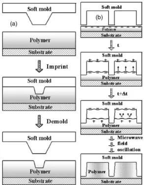
The use of nontraditional lithography techniques, i.e., those using molds, for pattern generation has several advan-tages over the relatively more costly conventional photon and electron lithography methods. When the mold is a hard material, usually fabricated from silicon or fused silica sub-strates, the approach is known as “hard imprint lithography.”1,2 Imprint lithography requires tools that can offer either the high pressure3required for pattern definition or UV light4 for curing of the monomer. When the mold is soft, e.g., when the mold material is an elastomer, the litho-graphic method is referred to as “soft lithography.”5 If the pattern on the soft mold is pressed forcefully into the poly-meric material coated onto the substrate, the pattern dimen-sions achieved关Fig. 1共a兲兴 are narrower than those of mold itself because of the compression effect of the elastomer upon the applied force.6 Indeed, with soft mold imprint methods it is not easy to control the pattern dimensions be-cause of the effects of elastic deformation. In comparison, soft-mold-induced self-construction共SMISC兲 关Fig.1共b兲兴 has
several advantages: patterns having dimensions identical to those of the mold pattern, a reduced number of fabrication steps, the avoidance of using highly expensive exposure tools, and low cutting costs.7–9
The method used to form the self-construction pattern is complex; it relies upon the effects of the electric field gradi-ent, surface tension, and/or dispersive interactions.9–12 The prerequisite for the SMISC is to melt the polymer by raising the film’s temperature above the glass transition temperature 共Tg兲. The melting polymer is attracted upward, against the
gravitational force and surface tension, to the mold surface. Several experimental and theoretical reports suggest9,10 that the rigid mold-induced pattern first grows at the site of a local strong electric field. The most challenging aspect of the present self-construction method is the long processing time 共from 10 min to several hours兲, in addition to the voltage
applied at both electrodes. A decrease in the pattern growth time is desirable.
We present a rapid microwave-assisted SMISC pattern-ing technique uspattern-ing a polymeric soft mold. A CEM MARS-5 microwave system13 was used in this study, with the turn-table inside the instrument rotated to randomize the direction of electromagnetic absorption. Prior to soft mold fabrication, we used a Canon I-line stepper and a LAM etcher to fabri-cate the silicon master with the following dimensions: 3m lines, 1.5m spaces, and 500 nm thickness. The master was then immersed into the antisticking agent solution according
a兲Electronic mail: [email protected]
FIG. 1. Schematic illustration共not to scale兲 of 共a兲 soft mold imprinting under a force field and共b兲 soft-mold-induced self-construction under a mi-crowave field.
APPLIED PHYSICS LETTERS 90, 191901共2007兲
0003-6951/2007/90共19兲/191901/3/$23.00 90, 191901-1 © 2007 American Institute of Physics This article is copyrighted as indicated in the article. Reuse of AIP content is subject to the terms at: http://scitation.aip.org/termsconditions. Downloaded to IP:
to a procedure described previously.2The flexible soft mold was fabricated from the silicon master. The Sylgard 184 agent 共Dow Corning兲 was mixed at a ratio of 10:1 共rubber base:cure兲 to form the polydimethylsiloxane 共PDMS兲 solu-tion. The solution was degassed within a vacuum chamber and then poured onto the silicon master and cured at 70 ° C for 1 h to provide the PDMS mold. The polymeric photore-sist共FH-6400L, Fujifilm Arch兲, which contained ⬃20% no-volak polymer 共average molecular weight: 5321 g/mol兲, ⬃60% ethyl lactate, ⬃15% ethyl-3-ethoxy propionate, and ⬃5% diazonaphthoquinone, was spin coated to a thickness of 500 nm onto the silicon substrate. Fluorescent rhodamine B was spiked at a concentration of 8⫻10−4M into the
poly-mer solution prior to film formation. A previously described optical system14 was used for fluorescence intensity mea-surements.
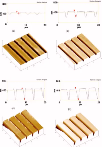
The morphologies of the SMISC patterns after various irradiation times are depicted in Fig.2; they were recorded in the tapping mode 共300 kHz兲 using a Veeco DI5000 atomic force microscope. The marked step heights were 67, 242, 471, and 489 nm for microwave irradiation times of 20, 40, 60, and 180 s, respectively; i.e., the dimensions of the poly-mer patterns increased gradually with respect to the irradia-tion times. None of the samples in Fig.2 exhibited undula-tions in the surface morphology of its novolak polymer patterns. This result for patterning under microwave irradia-tion is quite different from the patterns obtained when using either a strong electric force or a temperature cycle induced by surface tension and electrostatic force. Schaffer et al.10
observed surface undulations that were due to a film desta-bilization effect caused by the strong electric field. They claimed that the pattern could not be achieved in the absence of an applied electric field. Wu and Chou were able to grow a polymer pattern without applying an external electric field by taking advantage of the competition between the instabil-ity arising from the electrostatic force and the stabilization effect provided by the surface tension force.9 In our case, dipole rotation from the residual solvent and diazonaphtho-quinone in the photoresist film played an important role in providing rapid dielectric heating. At 2.45 GHz, the field os-cillates 4.9⫻109times/ s. The electromagnetic wave quickly
induces a temperature increase in the photoresist film, whereas the PDMS remains at a relatively lower temperature because of its low dissipation factor共tan␦Ⰶ0.001兲.15In ad-dition, the electromagnetic field in the microwave oven os-cillated in a random direction. This result implies that the external electric field on the SMISC sample may oscillate with time. Therefore, the dipole moment from charge sepa-ration on both the surfaces also varied with the field oscilla-tion. The field oscillation关e.g., from t to t+⌬t in Fig.1共b兲兴 may allow the polymer molecule to relax during pattern growth, i.e., the polymer molecules become disentangled. If the electric field is unidirectional, as in the case of Schaffer
et al.,10 the annealing time for pattern growth must be very long共⬎10 h兲 because the force disentangles only those mol-ecules that are aligned with the electric field. The advantage of the microwave-assisted SMISC approach is that it allows the polymer pattern to grow efficiently under a randomly distributed electric field.
The total surface energy7,9is another decisive parameter that affects pattern formation. Together with the Lifshitz-van der Waals 共LW兲 and Lewis acid-base 共AB兲 theories,16 the detailed energy contributions from the polymeric polar and apolar terms can be extracted individually. Surface tension 共␥i兲 of a phase i can be expressed as ␥i=␥LWi +␥iAB=␥iLW
+ 2冑␥i +␥ i −, where␥ i LWand␥ i
ABrepresent the dispersion
共apo-lar兲 and polar terms of the surface tension, respectively, and
␥i+ and ␥i− are the electron acceptor and electron donor
pa-rameters, respectively, in the polar part. The following con-tact angle equilibrium, based on the Young-Dupre equation, was formulated16by van Oss et al. to describe the interfacial tension between the liquid共L兲 and the polymer surface 共S兲,
共1 + cos兲␥L= 2共冑␥S LW␥ L LW +
冑
␥S +␥ L − +冑
␥S −␥ L +兲,whereis the contact angle determined using three different liquids with known values of ␥LLW, ␥L+, and ␥L−, e.g., water 共21.8, 25.5, and 25.5 mJ/m2, respectively兲, ethylene glycol
共29, 1.92, and 47 mJ/m2, respectively兲, and diiodomethane
共50.8, 0, and 0 mJ/m2, respectively兲.
For the novolak polymer film, the contact angles of wa-ter, ethylene glycol, and diiodomethane were 72.9°, 74.1°, and 31.9°, respectively, whereas they were 111.2°, 114.8°, and 96.7°, respectively, for the PDMS surface coated with the antisticking agent. Hence, the calculated values of the surface tensions ␥SLW, ␥S+, and ␥S− for the novolak polymer film were 56.3, 43.4, 1.93, and 21.4 mJ/ m2, respectively. Similarly, the corresponding surface tensions for the PDMS surface coated with the antisticking agent were 14.1, 9.91, 0.69, and 6.36 mJ/ m2, respectively. The novolak polymer
film has very much larger values for the Lifshitz-van der Waals共43.4 mJ/m2兲 and Lewis electron donor 共21.4 mJ/m2兲
FIG. 2. Growth of polymer patterns through SMISC after microwave irra-diation for共a兲 20, 共b兲 40, 共c兲 60, and 共d兲 180 s.
191901-2 Ko et al. Appl. Phys. Lett. 90, 191901共2007兲
This article is copyrighted as indicated in the article. Reuse of AIP content is subject to the terms at: http://scitation.aip.org/termsconditions. Downloaded to IP: 140.113.38.11 On: Thu, 01 May 2014 00:29:49
terms than does the PDMS surface coated with the antistick-ing agent. Durantistick-ing the SMISC process, the total surface en-ergy of the PDMS surface coated with the antisticking agent is only one quarter that of the novolak polymer. Thus, ther-modynamically, a driving force arises to minimize the sur-face tension of the novolak polymer by adsorption onto the surface of the PDMS mold. In addition to the electrostatic attraction, the surface tension—mainly from the Lifshitz-van der Waals interaction—also contributes to the pattern forma-tion.
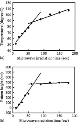
Figure3共a兲depicts a plot of the temperature of the poly-mer film with respect to the microwave irradiation time. The temperature increased linearly with the time 共slope: 0.638 ° C / s兲 during the first stage 共10–60 s兲 of microwave irradiation. The heating rate decreased, however, to 0.184 ° C / s during the latter stage共60–180 s兲. We attribute this behavior to the intrinsic property of the dissipation factor for the novolak resist. The efficiency of microwave absorp-tion during the first stage共10–60 s兲 was approximately 3.5-fold higher than that during the latter stage共60–180 s兲. This phenomenon is related to the solvent effect: the coexisting solvent in the film evaporated rapidly at higher temperatures and, therefore, the polymer film’s dissipation factor reduced accordingly. The film’s solvent had evaporated totally after approximately 60 s of microwave irradiation.
Figure3共b兲displays a plot of the pattern height obtained through SMISC as a function of the microwave irradiation time. The pattern height increased gradually with linearity共at a rate of 8.89 nm/ s兲 with respect to the irradiation time dur-ing first stage 共10–60 s兲, but leveled off during the latter
stage共60–180 s兲 as a result of the pattern reaching its physi-cal limits. We note that no pattern formed after irradiation for 10 s because the film’s temperature was only 51 ° C, whereas a 20 s irradiation共equivalent to 62.5 °C兲 produced a 67 nm polymer pattern through the synergetic effects of the electro-static and surface tension forces. This temperature after 10 s of microwave irradiation was lower than the Tg of the
no-volak resist共i.e., 60.5 °C兲; thus, it could not induce pattern formation. The great advantage of microwave irradiation is that a 471-nm-high pattern can be grown after irradiation for only 60 s, which is a significantly shorter time than those reported previously.7–10The step height of the pattern gradu-ally closed in on the mold depth upon increasing the irradia-tion time from 60 共471 nm兲 to 180 s 共489 nm兲. This result suggests that most of the surroundings of the novolak pattern surface after 60 s were stabilized by the PDMS surface, greatly reducing the surface tension forces for the growing pattern. Once pattern growth had concluded, demolding of the polymer pattern from the flexible PDMS mold was favor-able because of the low surface tension of the PDMS mold modified with the antisticking agent.
In summary, we have developed a rapid 共1 min兲 tech-nique for soft-mold-induced pattern growth under a micro-wave field. Both electrostatic forces and surface tension ef-fects contribute to the origin of pattern growth. The low surface tension of the mold surface, which had been modi-fied with an immobilized antisticking agent, facilitated the demolding process.
This study was supported financially by the National Science Council, Taiwan, through Contracts Nos. NSC 95-2120-M-009-003 and NSC 95-2113-M-009-032-MY3.
1S. Y. Chou, P. R. Krauss, and P. J. Renstrom, Appl. Phys. Lett. 67, 3114
共1995兲.
2J.-K. Chen, F.-H. Ko, K.-F. Hsieh, C.-T. Chou, and F.-C. Chang, J. Vac.
Sci. Technol. B 22, 3233共2004兲.
3S. Y. Chou, P. R. Krauss, and P. T. Reustrom, Science 272, 85共1996兲. 4D. J. Resnick, W. J. Dauksher, D. Mancini, K. J. Nordquist, E. Ainley, K.
Gehoski, J. H. Baker, T. C. Bailey, B. J. Choi, S. Johnson, S. V. Sreenivasan, J. G. Ekerdt, and C. G. Willson, J. Microlithogr., Microfabr., Microsyst. 1, 284共2002兲.
5Y. Xia and G. M. Whitesides, Angew. Chem., Int. Ed. 37, 550共1998兲. 6K.-S. Chen, I.-K. Lin, and F.-H. Ko, J. Micromech. Microeng. 15, 1894
共2005兲.
7S. Y. Chou, L. Zhuang, and L. J. Guo, Appl. Phys. Lett. 75, 1004共1999兲. 8Y. S. Kim, K. Y. Suh, and H. H. Lee, Appl. Phys. Lett. 79, 2285共2001兲. 9L. Wu and S. Y. Chou, Appl. Phys. Lett. 82, 3200共2003兲.
10E. Schaffer, T. Thurn-Albrecht, T. P. Russell, and U. Steiner, Nature
共London兲 403, 874 共2000兲.
11Z. Suo and J. Liang, Appl. Phys. Lett. 78, 3971共2001兲. 12S. Herminghaus, Phys. Rev. Lett. 83, 2359共1999兲.
13H. M. Kingston and L. B. Jassie, Introduction to Microwave Sample
Preparation, 1st ed.共ACS, Washington, DC, 1988兲, Chap. 6, p. 102.
14F.-H. Ko, L.-Y. Weng, C.-J. Ko, and T.-C. Chu, Microelectron. Eng. 83,
864共2006兲.
15J. C. Lotters, W. Olthuis, P. H. Veltink, and P. Bergveld, J. Micromech.
Microeng. 7, 145共1997兲.
16C. J. van Oss, M. K. Chaudhury, and R. J. Good, Chem. Rev.
共Washing-ton, D.C.兲 88, 927 共1988兲. FIG. 3. Relationships between the microwave irradiation time and共a兲 the
temperature of the polymer film and共b兲 the pattern height after SMISC.
191901-3 Ko et al. Appl. Phys. Lett. 90, 191901共2007兲
This article is copyrighted as indicated in the article. Reuse of AIP content is subject to the terms at: http://scitation.aip.org/termsconditions. Downloaded to IP: 140.113.38.11 On: Thu, 01 May 2014 00:29:49