Design of binary long-period fiber grating filters by
the inverse-scattering method
with genetic algorithm optimization
Gia-Wei Chern and Lon A. WangDepartment of Electrical Engineering and Institute of Electro-Optical Engineering, National Taiwan University, Taipei, Taiwan, China
Received February 23, 2001; revised manuscript received August 2, 2001; accepted August 30, 2001 An approach is presented to the design of binary long-period fiber grating (LPFG) filters based on the Gel’fand–Levitan–Marchenko (GLM) inverse-scattering method and genetic algorithm optimization. The nonuniform coupling strength of the binary grating can be realized by varying the local duty ratio. A coupled-mode theory combined with the Poisson sum formula for treating the binary index perturbation is developed for the application of the GLM synthesis method. Since the coupled-mode theory, which smears out the dis-crete coupling nature, can be regarded only as an approximation to the modeling of a binary LPFG, we use instead the transfer-matrix model to analyze the coupling behavior of a nonuniform binary LPFG. Based on the synthesized grating patterns from the GLM method, a real-coded genetic algorithm with the transfer-matrix model is used to compensate for the discrepancies resulting from use of the coupled-mode theory and to optimize the design. We exemplify the above procedure by designing a flatband LPFG filter and a high-visibility all-fiber Mach–Zehnder filter. © 2002 Optical Society of America
OCIS codes: 050.2770, 060.2310, 060.2340.
1. INTRODUCTION
A long-period fiber grating (LPFG) provides transmission-type loss filters by coupling optical power from the funda-mental core mode to the phase-matched cladding modes.1,2 The transmission spectrum of an LPFG con-sists of many dips that can be attributed to light cou-plings from the core mode to various cladding modes. Such all-fiber optical filters play an important role in op-tical communication systems. One important application of an LPFG is as a gain equalizer for an erbium-doped fi-ber amplifier (EDFA).3 The transmission dip of a uni-form LPFG corresponding to a specific cladding mode resonance has a sinclike profile with appreciable side-lobes. To construct a loss filter with an inverted excess gain spectrum of the EDFA, two uniform LPFGs with dif-ferent loss depths and center wavelengths are concat-enated to realize the desired filter response in Ref. 3. When a phase shift is placed in the middle point of a uni-form LPFG and the length of the phase shift is properly adjusted, the original loss dip corresponding to coupling from the core mode to a specific cladding mode splits into two dips, with relative peak losses controlled by the amount of the inserted phase shift. Such an LPFG can also be used as a gain-flattening filter for an EDFA.4 Re-cently, Bae et al. proposed a multiport lattice filter model for synthesizing piecewise-uniform LPFGs and applied it to the gain equalization of an EDFA.5 In addition to gain equalization, other optical communication applications may require special filters with arbitrary amplitude and phase responses. It is the goal of this paper to propose a general solution to the synthesis problem of a nonuniform binary LPFG.
Many methods have been proposed to fabricate a
complex-patterned fiber Bragg grating (FBG) whose pe-riod is submicrometer; e.g., by the moving fiber-scanning beam technique.6 Conversely, since the grating period of an LPFG is tens to hundreds of micrometers, the line-width of the mask for fabricating a complex nonuniform LPFG will be larger. Since most LPFGs are fabricated by using amplitude masks, the resultant LPFG assumes a binarylike index variation. Those regions exposed to ul-traviolet irradiation will thus be termed as regions 1, in which the core index is slightly increased as a result of photosensitivity of the germanosilicate core. The other regions are of a conventional fiber structure and will be referred to as regions 0. The transfer-matrix method for modeling the photoinduced binary LPFG based on a mode-matching technique and perturbation expansions have recently been developed by the authors in Ref. 7. Nonuniformity of the coupling strength of a binarylike waveguide grating, e.g., a grating-assisted codirectional coupler (GACC), can be realized by varying the local duty ratios.8,9 We shall use this principle to propose a design procedure for a nonuniform binary LPFG with the desired spectral response in the following and use the transfer-matrix model to analyze the grating response. Unlike the fabrication of an FBG, this method has the advantage that no scanning steps or positioning facilities are needed for the fabrication of the complex-patterned LPFG. Once the variation of the duty ratio and the local period is de-termined for the binary LPFG with the desired spectrum, one has only to fabricate the amplitude mask with the de-signed pattern of 0s and 1s. By direct exposure through the amplitude mask, the designed pattern can easily be transferred to a fiber. Our procedure for the design of a binary LPFG is as follows. A coupled-mode theory based
on the Poisson sum formula for treating the nonuniform binary index perturbation is developed for the analysis of a nonuniform binary grating.10 Then, by applying the well-developed Gel’fand–Levitan–Marchenko (GLM) inverse-scattering method,11 one can determine the de-sired variation of duty ratio and local period. The GLM inverse-scattering method has been successfully applied to the filter design of an FBG (e.g., Poladian12and Feced
et al.13). However, a discrepancy from the desired filter response arises when the transmission spectrum of the LPFG is calculated by employing the transfer-matrix model with grating parameters derived from the GLM method. This is because the GLM method is based on the coupled-mode theory, which smears out the discrete coupling characteristic of a binary grating, in which mode couplings are assumed to take place only at the heteroint-erfaces of regions 0 and 1. In addition, we define a di-mensionless parameter that can be used to characterize the self-coupling effect for any GACC. And it is found that the larger the parameter, the greater the correspond-ing discrepancy from the desired spectrum. A genetic al-gorithm is then used to compensate for the effect of self-couplings and to optimize the designed grating pattern.
The remainder of this paper is organized as follows. In Section 2, we first develop a coupled-mode theory based on the Poisson sum formula for analysis and synthesis of nonuniform binary grating filters. The index perturba-tion of a binary grating is transformed into a quasi-Fourier series whose expansion coefficients act as the ta-pered coupling constants. Coupled-mode equations are then used to analyze the grating responses. The discus-sion follows closely our previous work on the design of GACC filters.10 Section 3 is devoted to the transfer-matrix model for binary LPFGs. We reformulate the method for connection with the result of coupled-mode theory. An effective local coupling coefficient is derived by using the matrix method and shows discrepancies from the coupling coefficient derived from the quasi-Fourier se-ries in Section 2. It is shown that the discrepancy is mainly due to the nonzero difference between the self-coupling constants of the two resonantly coupled modes. In Section 4, we apply the method to design a flatband grating filter. A genetic algorithm is used to compensate for the discrepancies and to optimize the derived grating pattern from the GLM method. By symmetrically cas-cading a pair of the above designed flatband LPFG filters, we obtain an all-fiber Mach–Zehnder (MZ) filter. We cal-culate the filter response by taking into account the wave-guide dispersion, and the spectrum of the MZ filter shows a high fringe visibility. Finally, we make our conclusion in Section 5.
2. COUPLED-MODE THEORY FOR
NONUNIFORM BINARY WAVEGUIDE
GRATINGS
In this section, we will develop the coupled-mode theory for nonuniform binary waveguide gratings. The index perturbations of a binary grating take only two values for a specific transverse part, corresponding to regions 1 and 0. Nonuniformity of the grating is due to the varying lo-cal duty ratios and grating periods. We first use the
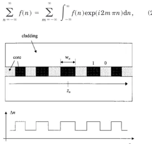
Pois-son sum formula to derive the quasi-Fourier-series expan-sion of the index perturbation for such nonuniform binary gratings. The expansion coefficients in the case of non-uniformity are also functions of the longitudinal distance. Then conventional coupled-mode theory is used to de-scribe mode couplings of the grating. The zeroth-order expansion coefficient function contributes to self-couplings of the interacting guided modes, which will modify the corresponding propagation constants, while the phase-matched mth-order term is responsible for the energy transfer between the resonantly coupled modes. The following discussion parallels closely the analysis of a nonuniform GACC in Ref. 10. A schematic diagram of the index perturbation of a nonuniform binary LPFG is shown in Fig. 1. Here we have chosen the z axis as the longitudinal direction of the grating. We take the trans-verse guiding structure of region 0 as the unperturbed one and let⌬ng2(x, y) be the index perturbation of region 1. The index perturbation of the photoinduced binary LPFG is⌬ng2⬵ 2n
co⌬nUVin the fiber core and zero else-where, where ⌬nUV is the photoinduced index change. The center position of the nth region 1 is designated as
zn, and the corresponding width as wn. Then we can ex-press the index perturbation as follows:
⌬n2共x, y, z兲 ⫽
兺
n⫽1 N ⌬ng2共x, y兲u冉
z ⫺ zn wn冊
, (1)where u(z) is the unit square function, which is unity when兩z兩⭐ 0.5 and zero elsewhere. The summation can be formally extended from ⫺⬁ to ⬁ if one assumes that
wn⫽ 0 for n ⬍ 1 or n ⬎ N. The center positions and widths of region 1 are regarded as sampled values of two continuous functions; i.e., zn⫽ z(n) and wn⫽ w(n). We next transform the above summation into a quasi-Fourier-series expansion by invoking the Poisson sum for-mula. This formula was originally adopted by Ishimaru in analyzing the array factor of a nonuniformly spaced an-tenna array.14 The Poisson formula is
兺
n⫽⫺⬁ ⬁ f共n兲 ⫽兺
m⫽⫺⬁ ⬁冕
⫺⬁ ⬁ f共n兲exp共i2mn兲dn, (2)Fig. 1. Schematic diagram of a binary LPFG. The shadowed fiber core corresponds to region 1, while the dotted one is region 0. Also shown is the index perturbation along the longitudinal distance.
where f(n) is a continuous function of n. The trans-formed index perturbation becomes
⌬n2共x, y, z兲 ⫽ ⌬ng2共x, y兲
兺
m⫽⫺⬁ ⬁冕
⫺⬁ ⬁ u冋
z⫺ z共n兲 w共n兲册
⫻ exp共i2mn兲dn. (3)Note that the summation over m is basically a generali-zation of the conventional Fourier-series expansion. The expansion coefficients in Eq. (3) are also functions of the longitudinal distance. Since znalways increases with n, the position function z(n) is a monotonically increasing function and is thus invertible. Let the inverse function be n(z), which is called the source-number function.14 Since the grating is assumed to be almost periodic, this function takes the following form:
n⫽ n共z兲 ⫽ z
⌳
¯ ⫹共z兲, (4)
where⌳¯ is a reference period and(z) is a slowly varying function of z. Additionally, (z) Ⰶ 1 for an almost-periodic grating. The derivative of the source-number function, dn/dz⬵ ⌬n/⌬zn⫹1,n⫽ 1/⌳n, has the physical meaning of the inverse of the local period; thus we define the local period function⌳(z) as
1 ⌳共z兲 ⬅ dn dz ⫽ 1 ⌳¯ ⫹ d dz. (5)
We also define the local duty ratio(z) as 共z兲 ⬅ w共z兲
⌳共z兲. (6)
By changing integration variables from n to z in the quasi-Fourier-series expansion (3) and using the slowly varying properties of the local parameters, we obtain the following result (the details of the derivation can be found in Ref. 10): ⌬n2共x, y, z兲 ⫽
兺
m⫽⫺⬁ ⬁ ⌬nˆm2共x, y; z兲 ⫻ exp冋
im冕
0 z 2 ⌳共z⬘兲dz⬘册
, (7) with the expansion coefficient functions⌬nˆm2共x, y; z兲 ⫽
再
⌬ng 2共x, y兲共z兲, m⫽ 0 ⌬ng 2共x, y兲sin关共z兲m兴 m , m⫽ 0 . (8) Note that in Eq. (7), the quasi-Fourier series is expanded by use of the local grating period⌳(z) in integral form but not the constant reference period ⌳¯ . Now we apply the above results to the codirectional couplings of guided modes in binary gratings, e.g., GACCs or LPFGs. We consider the case of resonant two-mode couplings and let the two nearly phase-matched modes be modes 1 and 2. For practicality, the two resonantly coupled modes of a bi-nary LPFG are chosen to be the fundamental core mode(LP01) and the cladding mode of order (LP0). By ne-glecting the backward-propagating modes, we can write the total electric field as
E共r兲 ⫽
兺
j⫽1,2Aj共z兲ej共x, y兲 ⫽j
兺
⫽1,2aj共z兲exp共ijz兲ej共x, y兲, (9) where (ej,hj) are the mode fields, which are assumed to be mutually orthogonal and normalized according to1 2
冕
Aco关ej⫻ hk兴• z dA ⫽␦jk 共 j, k ⫽ 1, 2兲. (10) Here␦jkis the Kronecker delta symbol. jis the propa-gation constant of mode j, and aj(z) is the corresponding slowly varying mode amplitude. Without loss of general-ity, we shall now take the resonance grating order to be
m ⫽ 1. By substituting Eqs. (7) and (8) into the
coupled-mode equation,2,15 we obtain the evolution of the mode amplitudes:
da1
dz ⫽ i⌬1共z兲a1⫹ iK共z兲a2 ⫻ exp
再
⫺i冕
0 z冋
1⫺2⫺ 2 ⌳共z兲册
dz冎
, da2dz ⫽ i⌬2共z兲a2⫹ iK*共z兲a1 ⫻ exp
再
i冕
0 z冋
1⫺ 2⫺ 2 ⌳共z兲册dz冎
, (11) where ⌬j(z) is the local correction to the propagation constant of mode j, given by⌬j共z兲 ⬅jj共z兲 共 j ⫽ 1, 2兲, (12) and the cross-coupling coefficient is
K共z兲 ⬅12
sin关共z兲兴
. (13)
Here we introduce the following coupling constant: jk⫽0 4
冕
A⬁⌬ng 2冉
e tj * • etk⫹ n¯ 2 n2ezj*ezk冊
dA, (14)where n¯2(x, y) is the transverse index profile of region 0,
n2⫽ n¯2⫹ ⌬ng2 is that of region 1, and the subscripts t and z indicate the transverse and longitudinal parts of the electric fields, respectively. With the mode amplitude transformations
aˆj共z兲 ⫽ aj共z兲exp
冋
⫺i冕
0z
⌬j共z⬘兲dz⬘
册
共 j ⫽ 1, 2兲, (15) the coupled-mode equations (11) becomedaˆ1
dz ⫽ iK共z兲aˆ2exp
冋
⫺2i冕
0 z ␦共z⬘兲dz⬘册
, daˆ2 dz ⫽ iK*共z兲aˆ1exp冋
2i冕
0 z ␦共z⬘兲dz⬘册
, (16)where the local detuning parameter is defined as ␦共z兲 ⫽ 1 2
冋
1⫺2⫺ 2 ⌳共z兲 ⫹ ⌬1共z兲 ⫺ ⌬2共z兲册
⫽ ⫹ 1 2冋
⌬1共z兲 ⫺ ⌬2共z兲 ⫺ 2 d dz册
. (17) In the above expression, we also introduce thez-independent detuning parameter, which is a function
of the wavelength: 共兲 ⫽ 1
2
冋
1共兲 ⫺2共兲 ⫺ 2⌳¯
册
. (18)The resonance condition implies that ⬵ 0 for the wave-length range under consideration. We now make the fol-lowing variable transformations:
1共z, 兲 ⫽ aˆ1共z兲exp共iz兲,
2共z, 兲 ⫽ aˆ2共z兲exp共⫺iz兲. (19) The transformed mode amplitudes satisfy the Zakharov– Shabat (ZS) equation:
d1共z, 兲/dz ⫺ i1共z, 兲 ⫽ q共z兲2共z, 兲,
d2共z, 兲/dz ⫹ i2共z, 兲 ⫽ ⫺q*共z兲1共z, 兲, (20) where q(z) is the complex coupling potential given by
q共z兲 ⫽ i兵12sin关共z兲兴/其exp关i共z兲兴 (21) with the phase function
共z兲 ⫽ 2共z兲 ⫺ 共11⫺22兲
冕
0z
共z⬘兲dz⬘. (22) Given the scattering coefficient, which is related to the fil-ter response, the GLM inverse-scatfil-tering method can be used to derive the corresponding coupling potential
q(z).11 With the aid of Eqs. (21) and (22), the grating pattern can thus be derived as shown in Section 4.
3. TRANSFER-MATRIX METHOD FOR
NONUNIFORM BINARY WAVEGUIDE
GRATINGS
We have previously developed a transfer-matrix method based on a mode-matching technique for the modeling of a photoinduced binary LPFG.7 In this approach, mode fields of region 1 are derived from those of region 0 by per-turbation expansion to first order along with the corre-sponding propagation constants. The expansion coeffi-cients to first order are successively expressed by the parameters used in coupled-mode theory. By requiring the continuities of the tangential electric and magnetic fields on the heterointerfaces of regions 0 and 1, we can use a set of fundamental transfer matrices to describe the evolution of mode amplitudes as the wave field propa-gates through the LPFG. The details of the transfer-matrix method for a binary LPFG can be found in Ref. 7. In the following, we shall briefly review the fundamental transfer matrices and apply these matrices to the nonuni-form binary LPFG shown in Fig. 1. Following the nota-tion convennota-tions in Ref. 7, we will henceforward use
sym-bols with a bar above to represent quantities in region 0, while the unbarred ones are for region 1. Let the two mutually coupled-mode amplitudes be represented as a column vector A⫽ (A1, A2)T[cf. Eq. (9)], where the su-perscript T indicate transpose. For the incidence from region 0 to region 1, the changes in mode amplitudes can be expressed as A⫽ F(1兩0)A¯ with the following interface matrix:
F共1兩0兲⫽
冋
␣1 ␥ ⫺␥* ␣2册
. (23)
And similarly, for incidence from region 1 to region 0, we have A¯ ⫽ F(0兩1)A with
F共0兩1兲⫽
冋
␣1 ⫺␥ ␥* ␣2册
, (24)
where the off-diagonal element ␥ represents the cross-coupling through the heterointerface and is given by
␥ ⫽ 12 1⫺2
. (25)
␣1and␣2in Eqs. (23) and (24) are the self-transmission coefficients and are expressed by
␣j⫽ 1 ⫺ Dj/2 共 j ⫽ 1, 2兲, (26) where the explicit form of Djcan be found in Appendix A of Ref. 7. This term, Dj, accounts for the renormaliza-tion factor of the perturbed mode fields. In the ideal case of two-mode couplings, we shall assume that
␣1⫽␣2⫽
冑
1⫺ 兩␥兩2⬅ ␣. (27) As for free propagation through region 1, the mode ampli-tudes acquire a phase change and can be described by A(z)⫽ P(1)(z)A(0), where the phase matrix P(1)isP共1兲共z兲 ⫽
冋
exp关i共1⫹11兲z兴 00 exp关i共2⫹ 22兲z兴
册
.(28) And similarly, we have the following for region 0: A¯ (z) ⫽ P(0)(z)A¯ (0) with
P共0兲共z兲 ⫽
冋
exp共i1z兲 0 0 exp共i2z兲册
. (29)
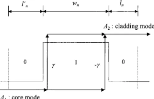
Now we consider a unit period centered at z⫽ zn as shown in Fig. 2. The local grating period corresponding to the nth region 1 is defined in the average sense:
⌳n⫽ 共1/2兲关共zn⫹1⫺ zn兲 ⫹ 共zn⫺ zn⫺1兲兴. (30) The length of the right region 0 is
ln⫽ 共1/2兲关共zn⫹1⫺ zn兲 ⫺ wn兴, (31) while that of the left is
ln⬘⫽ 共1/2兲关共zn⫺ zn⫺1兲 ⫺ wn兴. (32) Note that, from the above definition, we have wn⫹ ln ⫹ ln⬘⫽ ⌳n. The transfer matrix of the nth period is then given by
Fn⫽ P共0兲共ln兲F共0兩1兲P共1兲共wn兲F共1兩0兲P共0兲共ln⬘兲 ⫽ exp共in兲
冋
⫺⌫An ⌫nn
* An*
册
, (33)where the matrix elements are
An⫽ ␣2exp
冋
i 共⌬n⫹ ⌬¯n兲 ⫹n 2册
⫹ 兩␥兩2exp冋
⫺i共⌬n⫺ ⌬¯n兲 ⫹n 2册
, (34) ⌫n⫽ exp关i共1⫺ 2兲共ln⫺ ln⬘兲兴 ⫻ 共2i␣␥兲sin冉
⌬n⫹n 2冊
. (35)The following parameters are introduced:
n⫽¯⌳n⫹ 共11⫹22兲wn/2 (36) is the global phase shift through the nth period, ¯ ⫽ (1⫹2)/2 is the averaged propagation constant of the two modes,n⫽ wn/⌳nis the local duty ratio for the
nth period, and
⌬n⫽ 共1⫺ 2兲wn, ⌬¯n⫽ 共1⫺2兲共ln⫹ ln⬘兲 (37) are the phase differences of the two mode amplitudes within regions 1 and 0, respectively. We also define an important parameter characterizing the self-couplings:
⫽ 共11⫺22兲⌳¯ . (38) We now consider the connection between the transfer-matrix method and the coupled-mode theory by introduc-ing an effective couplintroduc-ing coefficient. Note that the
off-diagonal term of the transfer matrix Fn can be approximated in the continuous coupling sense as dA1/dz⬇ 关A1( n⫹ 1 ) ⫺ A1(n)兴 /⌳n⬇ exp(i¯)⌫*A2(n)/⌳¯ . Assuming that the grating parameters vary slowly enough that we may take ln⬵ ln⬘, we have
exp共in兲⌫n*⫽ exp
冋
i1ln⬘ ⫹ i共1⫹11兲wn 2
册
共i⌳¯ Kn兲 ⫻ exp冋
i共2⫹22兲wn
2 ⫹ i2ln
册
; (39) here we have introduced the following local effective cou-pling coefficient corresponding to K(z) in Eq. (13) of the coupled-mode theory:Kn⫽␣ 12
⫹ ˜sin关n共 ⫹ ⫹ ˜兲兴, (40) where ˜ ⫽ ⌳¯ is the normalized detuning. Expression (39) can be interpreted as follows. The combined cou-plings of mode amplitudes from core to cladding through the two heterointerfaces of the nth period (see Fig. 2) can be represented as a single coupling taking place at
z ⫽ zn with effective coupling Kn⌳¯ . This is also illus-trated in Fig. 3. Note that when Ⰶ 1 (small difference between self-coupling constants) and˜ Ⰶ 1 (narrow spec-tral range), expression (40) reduces to the result of coupled-mode theory [Eq. (13)]. However, the grating pe-riod of the LPFG is rather large; thus both and ˜ cannot be neglected completely. This is a special feature of the long periodicity. For a typical LPFG, the value of the self-coupling parameter is approximately ⬵01– 01co–co⌳¯ ⬵ 0.1 to 1, and max⌳¯ ⬵ 0.01 to 0.1; thus the deviation from the coupled-mode theory is appreciable, and com-pensation should be made to optimize the design.
4. FILTER DESIGN BASED ON THE
INVERSE-SCATTERING METHOD WITH
GENETIC ALGORITHM OPTIMIZATION
We will design a binary LPFG with flatband spectral re-sponse in this section. The design is based on the GLM inverse-scattering method combined with a genetic algo-rithm to optimize the grating pattern. The details of the GLM method can be found in Ref. 11. To apply the GLM inverse-scattering method, we must specify the scattering coefficient of the ZS equation (20), and in the forward-coupling case, one has to specify the following scattering coefficient10,11:
r共兲 ⫽ 2共L, 兲/1共L, 兲, (41) where L is the interaction length of the grating. Basi-cally, the GLM equations are a set of coupled integral equations used to solve the unknown coupling potential
q(z) given the scattering coefficient r(). Song and Shin11 showed that the GLM integral equations can be transformed into a set of linear equations for q(z) and thus can be exactly solved if r() is a rational function of . We will use this method in the following flatband LPFG filter design. The flatband filter is well
approxi-Fig. 2. Schematic diagram and corresponding parameters of a unit period. Also shown are couplings of the core mode to the phase-matched cladding mode through the two heterointerfaces.
Fig. 3. Equivalent coupling to that in Fig. 2 from the core mode to the cladding mode; here Knis the equivalent coupling
mated by a 13th-order Butterworth filter with maximum cross transmission being 0.5. The details of the design can be found in Refs. 10 and 16. The reason for choosing a cross transmission of 0.5 is as follows. We want to con-struct an all-fiber MZ filter by cascading two LPFGs.17,18 The first LPFG splits light into two paths: One is within the core mode, while the other is through the propagation of the cladding mode. The second LPFG then combines light beams from these two paths. From the theory of MZ interferometry, the best visibility will occur when the power-splitting ratio is 0.5.17,18 Once the coupling poten-tial is determined by the GLM method, the local duty ra-tio and period are obtained from Eqs. (21) and (22) as
共z兲 ⫽ 1 sin⫺1
冋
兩q共z兲兩 12册
, (42) 1 ⌳共z兲 ⫽ 1 ⌳¯ ⫹ 1 2 d dz ⫹ 共z兲 2⌳¯ . (43)From Eqs. (5) and (43), we can derive the source-number function as
n共z兲 ⫽
冕
0z dz⬘
⌳共z⬘兲, (44)
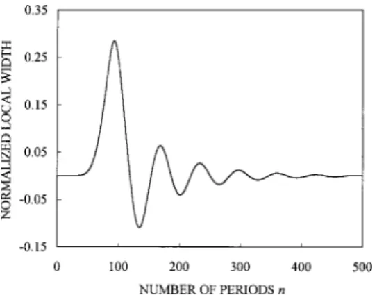
whose inverse gives the positions of region 1 in each riod. Then the corresponding parameters for the nth pe-riod are ⌳n⫽ ⌳(zn) and wn⫽ (zn)⌳nwith zn⫽ z(n). Figures 4 and 5 show the variation of normalized local width wn/⌳¯ and local period ⌳n/⌳¯ with respect to the number of periods derived by the GLM inverse-scattering method. Note that a sign change of the grating width wn indicates the insertion of a phase shift at the crossing point. And this is implemented in the transfer-matrix model by multiplying by a matrix P(0)(⌳¯ /2) at the corre-sponding point.
In Fig. 6, we calculate the corresponding cross-transmission spectrum by using the transfer-matrix method. The cross transmission is defined as the rela-tive power transfer from mode 1 to mode 2 at the exit end of the codirectional grating. It can be seen that the de-viation from the desired result is appreciable. As dis-cussed above, this is because the coupled-mode equation, as well as the ZS equation, is a continuous approximation to the discrete couplings of the binary LPFG. When we
use the transfer-matrix model to calculate the filter spec-trum of the grating pattern derived from the GLM method, there are significant discrepancies. This might be due to the smearing of the discrete couplings or to the effect of the self-couplings. Thus, based on the result from the GLM method, we use a genetic algorithm to com-pensate for these discrepancies and to optimize the grat-ing design. Genetic algorithms have been successfully applied to the design of various optical filters, including FBG,19thin-film,20and rugate21filters. A real-coded ge-netic algorithm20is used in our optimization of the grat-ing pattern. Let the grating parameters derived from the GLM method be (wn(GLM), ⌳n(GLM)) for n⫽ 1,2 ,..., N. We add a small correction to these parameters,
wn⫽ wn共GLM兲⫹ ⌬wn, ⌳n⫽ ⌳n共GLM兲⫹ ⌬⌳n, (45) and then use the genetic algorithm to optimize these cor-rections (⌬wn, ⌬⌳n). The genetic algorithm operates on a population of potential correction candidates. Each in-dividual of the population can be represented by the fol-lowing sequence:
x⫽兵⌬w1,⌬⌳1;⌬w2,⌬⌳2;...,⌬wn,⌬⌳N其. (46) A suitable merit function used to return a single real number reflecting the total fitness of a specific correction is given by21
Fig. 4. Variation of the normalized local width wn/⌳¯ obtained
from the GLM inverse-scattering method.
Fig. 5. Same as Fig. 4 but for the normalized local period⌳n/⌳¯ .
Fig. 6. Cross-transmission spectrum of the grating parameters in Figs. 4 and 5 calculated by the transfer-matrix model. The dotted lines represent the desired flatband spectrum.
F共x兲 ⫽
再
1 M兺
j⫽1 M冋
T共j;x兲 ⫺ Ttarget共j兲 dTj册
2冎
1/2 , (47) where T(j;x) is the cross transmission calculated by us-ing the transfer-matrix method with gratus-ing parameters given by sequence x at wavelength j, Ttarget(j) is the corresponding target cross transmission, and dTj is the tolerance at j. The genetic algorithm finds the opti-mum corrections x according to this figure of merit based on the rules of natural selections. Three primary opera-tions are used to evolve the population of candidate cor-rections: selection, crossover, and mutation. The de-tailed definitions of these operations for real-coded genetic algorithms can be found, for example, in Ref. 20. The optimized grating parameters are shown in Figs. 7 and 8. For comparison, in these figures, we also plot the results obtained by using only the GLM method. It can be seen that although the corrections to the local width are small, corrections to the local period are quite appre-ciable. In Fig. 9, we calculate the corresponding cross-transmission spectrum by the transfer-matrix model; it can be seen that the filter response is improved by the ge-netic algorithm.The above results are applied to the design of a binary LPFG with the following fiber parameters: core radius
aco⫽ 2.62m, cladding radius acl⫽ 62.5m, core index
nco⫽ 1.4557, and cladding index ncl⫽ 1.45. We choose
the resonant cladding mode to be LP05. The reference period is determined by⌳¯ ⫽ 0/(n01co⫺ n05cl) ⫽ 787.4m for center wavelength 0⫽ 1.55m. The calculated cross-coupling constant is 12⫽01– 05
co– cl ⫽ 0.266⌬n UV. The self-coupling constant for the core mode is 01– 05co– cl ⫽ 1.276⌬nUV, while that for the cladding mode is taken to be zero.2 The index modulation ⌬nUV⫽ 1.576 ⫻ 10⫺4. Figure 10 shows the transmission spectrum of the binary LPFG calculated by the transfer-method model taking into account the waveguide dispersion; it can be seen that a flatband transmission loss extends approxi-mately from 1535 to 1565 nm. It should be noted that the above analysis is basically applicable only to a given resonant cladding mode. This is because the difference between self-couplings 11⫺ 22 is dependent on which cladding mode is being considered and is also related to the cross-coupling constant12, which determines the de-sired transmission loss.
An all-fiber MZ filter with high fringe visibility can be constructed by symmetrically cascading two such LPFGs.17,18 The grating response is calculated as fol-lows. Let FLPFGbe the overall transfer matrix of a single flatband LPFG; then the transfer matrix corresponding to the MZ filter is
FMZ⫽ 共FLPFG兲TP共0兲共LMZ兲FLPFG, (48) where the superscript T indicates transpose of the trans-fer matrix, which physically reverses the ordering of the
Fig. 7. Variation of the normalized local width wn/⌳¯ obtained
from the GLM inverse-scattering method with genetic algorithm optimization. Also shown for comparison is the result obtained by using only the GLM method.
Fig. 8. Same as Fig. 7 but for the normalized local period⌳n/⌳¯ .
Fig. 9. Cross-transmission spectrum of the grating parameters in Figs. 7 and 8 optimized by genetic algorithm. The dotted lines represent the desired flatband spectrum.
Fig. 10. Transmission spectrum of the synthesized flatband bi-nary LPFG.
corresponding grating. The separation between the two gratings is chosen to be LMZ⫽ 30⌳¯ . Figure 11 shows the calculated transmission spectrum in linear scale. A fringe pattern with high visibility over a spectral range of approximately 30 nm is obtained. Such a filter may have potential applications in wavelength-division multiplex-ing systems.
5. CONCLUSION
We have presented a procedure for the design of binary LPFG filters based on the GLM inverse-scattering method with genetic algorithm optimization. The cou-pling strength of the binary LPFG is varied with the local duty ratio. The index variation of the binary LPFG is ex-panded into a quasi-Fourier series by the Poisson sum for-mula. The zeroth-order expansion coefficient contributes to the self-couplings of the interacting modes, while the phase-matched first-order term determines the taper function of the coupling coefficient. A coupled-mode equation is presented for the application of the GLM inverse-scattering method. The grating response is cal-culated by using a transfer-matrix model developed pre-viously by the authors. A connection between the transfer-matrix model and the coupled-mode theory is es-tablished for the nonuniform binary LPFG. It is found that the coupled-mode theory can serve only as an ap-proximate modeling to the binary grating, since the dis-crete coupling nature of the binary LPFG is smeared out. From the transfer-matrix model, we derive a generalized local coupling coefficient, which under certain conditions can be reduced to the result obtained from the coupled-mode theory. The grating parameters derived from the GLM inverse-scattering method are used as initial bases for the application of the genetic algorithm to optimize the grating design. We apply the above procedure to the design of a binary LPFG with flatband transmission spec-trum and show that by symmetric cascading of two such gratings a high-visibility all-fiber MZ filter can be con-structed.
ACKNOWLEDGMENTS
G. W. Chern is grateful to H. H. Liang for his help and useful discussions about the genetic algorithms. The au-thors are also grateful to the support in part by the
Na-tional Science Council in Taiwan, Republic of China (R.O.C.), under contract NSC 90-2215E-002-007 and by the Education Ministry in Taiwan, R.O.C., under contract 89-E-FA06-2-4.
Address correspondence to Lon A. Wang at the location on the title page or by phone, 23635251; fax, 886-2-23656327; or e-mail, [email protected].
REFERENCES
1. A. M. Vengsarkar, P. J. Lemaire, J. B. Judkins, V. Bhatia, T. Erdogan, and J. E. Sipe, ‘‘Long-period fiber gratings as band-rejection filters,’’ J. Lightwave Technol. 14, 58–65 (1996).
2. T. Erdogan, ‘‘Cladding-mode resonances in short- and long-period fiber grating filters,’’ J. Opt. Soc. Am. A 14, 1760– 1773 (1997).
3. A. M. Vengsarkar, J. R. Pedrazzani, J. B. Judkins, P. J. Le-maire, N. S. Bergano, and C. R. Davidson, ‘‘Long-period fiber-grating-based gain equalizers,’’ Opt. Lett. 21, 336–338 (1996).
4. J. R. Qian and H. F. Chen, ‘‘Gain flattening fibre filters us-ing phase-shifted long period fibre gratus-ings,’’ Electron. Lett.
34, 1132–1133 (1998).
5. J. Bae, J. Chun, and S. B. Lee, ‘‘Equalization of the non-flat erbium gain spectrum using the multiport lattice filter model,’’ in Optical Fiber Communications Conference, Vol. 2 of 2000 OSA Technical Digest Series (Optical Society of America, Washington, D.C., 2000), pp. 80–83.
6. W. H. Loh, M. J. Cole, M. N. Zervas, S. Barcelos, and R. L. Laming, ‘‘Complex grating structures with uniform phase masks based on the moving fiber-scanning beam tech-nique,’’ Opt. Lett. 20, 2051–2053 (1995).
7. G. W. Chern and L. A. Wang, ‘‘Transfer-matrix method based on perturbation expansion for periodic and quasi-periodic binary long-period gratings,’’ J. Opt. Soc. Am. A 16, 2675–2689 (1999).
8. H. Sakata, ‘‘Sidelobe suppression in grating-assisted wavelength-selective couplers,’’ Opt. Lett. 17, 463–465 (1992).
9. Y. H. Jan, G. A. Fish, L. A. Coldren, and S. P. DenBaars, ‘‘Demonstration of InP-InGaAsP vertical grating-assisted co-directional coupler filters and receivers with tapered cou-pling coefficient distributions,’’ IEEE Photon. Technol. Lett.
9, 994–996 (1997).
10. G. W. Chern and L. A. Wang, ‘‘Analysis and design of almost-periodic vertical-grating-assisted codirectional cou-pler filters with nonuniform duty ratios,’’ Appl. Opt. 39, 4629–4637 (2000).
11. G. H. Song and S. Y. Shin, ‘‘Design of corrugated wave-guide filters by the Gel’fand–Levitan–Marchenko inverse-scattering method,’’ J. Opt. Soc. Am. A 2, 1905–1915 (1985).
12. L. Poladian, ‘‘Simple grating synthesis algorithm,’’ Opt. Lett. 25, 787–789 (2000).
13. R. Feced, M. N. Zervas, and M. A. Muriel, ‘‘An efficient in-verse scattering algorithm for the design of nonuniform fi-ber Bragg gratings,’’ IEEE J. Quantum Electron. 35, 1105– 1115 (1999).
14. A. Ishimaru, ‘‘Theory of unequally spaced arrays,’’ IRE Trans. Antennas Propag. 10, 691–702 (1963).
15. A. W. Snyder and J. D. Love, Optical Waveguide Theory (Chapman & Hall, London, 1991).
16. K. A. Winick, ‘‘Design of grating-assisted waveguide cou-plers with weighted coupling,’’ J. Lightwave Technol. 9, 1481–1492 (1991).
17. X. J. Gu, ‘‘Wavelength-division multiplexing isolation fiber filter and light source using cascaded long-period fiber grat-ings,’’ Opt. Lett. 23, 509–510 (1998).
18. B. H. Lee and J. Nishii, ‘‘Dependence of fringe spacing on
Fig. 11. Transmission spectrum of the all-fiber MZ filter com-posed of two symmetrically cascaded flatband LPFGs.
the grating separation in a long-period fiber grating pair,’’ Appl. Opt. 38, 3450–3459 (1999).
19. J. Skaar and K. M. Risvik, ‘‘A genetic algorithm for the in-verse problem in synthesis of fiber gratings,’’ J. Lightwave Technol. 16, 1928–1932 (1998).
20. E. Michielssen, S. Ranjithan, and R. Mittra, ‘‘Optimal
multilayer filter design using real coded genetic algorithm,’’ IEE Proc. J Optoelectron. 139, 413–420 (1992).
21. P. L. Swart, A. P. Kotze, and B. M. Lacquet, ‘‘Effects of the nature of the starting population on the properties of rug-ate filters designed with the genetic algorithm,’’ J. Light-wave Technol. 18, 853–859 (2000).