High-brightness relaxed-bend state in a pi cell stabilized by synchronized
polymerization
Bo-Ru Yang, Steve J. Elston, Peter Raynes, and Han-Ping D. Shieh
Citation: Applied Physics Letters 92, 221109 (2008); doi: 10.1063/1.2939559
View online: http://dx.doi.org/10.1063/1.2939559
View Table of Contents: http://scitation.aip.org/content/aip/journal/apl/92/22?ver=pdfcov Published by the AIP Publishing
Articles you may be interested in
A microsecond-response polymer-stabilized blue phase liquid crystal Appl. Phys. Lett. 99, 201105 (2011); 10.1063/1.3662391
Twisted liquid crystal pi cell stabilized by polymer-sustained alignment Appl. Phys. Lett. 93, 221103 (2008); 10.1063/1.3040325
Highly circularly polarized electroluminescence from organic light-emitting diodes with wide-band reflective polymeric cholesteric liquid crystal films
Appl. Phys. Lett. 90, 211106 (2007); 10.1063/1.2741603
Short pitch cholesteric electro-optical device stabilized by nonuniform polymer network Appl. Phys. Lett. 86, 161118 (2005); 10.1063/1.1897057
Photoluminescence stability of a cyanoterphenyl chromophore in liquid crystalline polymeric systems J. Appl. Phys. 88, 7124 (2000); 10.1063/1.1323518
This article is copyrighted as indicated in the article. Reuse of AIP content is subject to the terms at: http://scitation.aip.org/termsconditions. Downloaded to IP: 140.113.38.11 On: Wed, 30 Apr 2014 23:03:32
High-brightness relaxed-bend state in a pi cell stabilized
by synchronized polymerization
Bo-Ru Yang,1,2,a兲 Steve J. Elston,1Peter Raynes,1and Han-Ping D. Shieh3
1
Department of Engineering Science, University of Oxford, Oxford OX1 3PJ, United Kingdom
2Department of Photonics and Institute of Electro-Optical Engineering, National Chiao Tung University,
Hsinchu 30010, Taiwan
3Department of Photonics and Display Institute, National Chiao Tung University, Hsinchu 30010, Taiwan
共Received 10 December 2007; accepted 15 May 2008; published online 5 June 2008兲
The authors report a synchronized polymer-stabilization technique which can be used to stabilize the nonpermanent states in liquid crystal devices. In this paper, a relaxed-bend state in a pi cell which has a lifetime of only 80 ms is observed and then stabilized by this proposed technique. After stabilizing, the pi cell is immune to undesirable recovery into the splay or twist states, and its optical contrast is much higher than that of the conventional polymer-stabilized pi cell. © 2008 American Institute of Physics. 关DOI:10.1063/1.2939559兴
The liquid crystal共LC兲 pi cell,1also known as the opti-cally compensated bend共OCB兲 mode,1–4is noted for its fast switching speed due to its symmetric LC director profile and parallel backflow. This kind of cell is normally operated in the bend state; however, because of the topological differ-ence between the ground splay state and the bend state, a nucleation transition has to be completed before operation. This transition can be initiated by applying a critical voltage, and then this voltage should be held to sustain the device in the bend state. However, the pi cell still has the tendency of recovering into the splay state.
To prevent this recovery, several techniques have been proposed.5–12 These can be classified into three categories. The first category is one that uses the splay states instead of the bend states.6The second category is to stabilize the twist or bend state.5,7,8,10–12However, in the former case, since the bend and twist states need different optical compensations,13 it is difficult to exploit the full optical dynamic range of both the bend and twist states. Also, the switching time associated with the twist state is much longer than that of the bend state, which is thus undesirable for fast switching devices. In the latter case, the stabilized pi cell has significant phase retar-dation suppression, which then decreases the contrast ratio of the pi cell. The third category is to use intermittent pulse signals to prevent the recovery from the bend state to the twist state.9 This method has been reported to maintain a relaxed-bend共RB兲 state, which has the highest phase retar-dation, or say the highest brightness, among the range of the bend states. However, there is still considerable tendency of the cell recovering from the bend state into the twist or splay states. Thus, in order to prevent this undesirable recovery, we aim to stabilize the pi cell device in the RB state and there-fore perform high optical contrast without the need for im-pulse driving.
A preliminary observation of the RB state is made. Ini-tially, we pick the empty cells with identical cell gap of 5.5m, and fill them with LC material E7 blended with 4% monomer mixture including 90% reactive mesogen共RM257 of Merck兲 and 10% photoinitiator 共Irgacure 907 of Ciba Spe-cialty Chemicals兲. The alignment layers of the pi cell devices
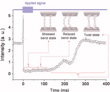
are parallel rubbed polyimide whose rubbing directions are placed parallel to the crossed polarizers. The driving signal is a 10 kHz, 20 Vpp, burst sine wave with 50 ms of pulse width. This high voltage impulse ensures the occurrence of the RB state. As shown in Fig.1, after removing the applied signal, the pi cell remains in the bend state for 80 ms and then transitions into the twist state. From this observation, we deduce that there exists an 80 ms nonpermanent RB state after the removal of the voltage impulse.
To stabilize the nonpermanent RB state, we set up a synchronized polymerization system which enables us to se-lect the specific state to be stabilized. As shown in Fig.2, an optical chopper is used to block the UV light and only let the UV light impinge on the pi cell during the desired state. That is, we synchronize the driving signal and the UV light im-pingement on the pi cell. Laser diode LD-1 and photodiode PD-1 are used to monitor the transmission of the pi cell device. Another paired LD-2 and PD-2 are used to trigger the driving signal for the pi cell. A further photodiode共PD-3兲 is
a兲Electronic mail: ybr.eo93g@nctu.edu.tw.
FIG. 1.共Color online兲 Oscilloscopic trace of the RB state formation and its collapsing into twist state. The rubbing direction of the pi cell is parallel to the crossed polarizers. The driving signal is set to 20 Vppfor 50 ms. After removing the voltage signal, the pi cell remains in the RB state for 80 ms.
APPLIED PHYSICS LETTERS 92, 221109共2008兲
0003-6951/2008/92共22兲/221109/3/$23.00 92, 221109-1 © 2008 American Institute of Physics This article is copyrighted as indicated in the article. Reuse of AIP content is subject to the terms at: http://scitation.aip.org/termsconditions. Downloaded to IP:
placed near the pi cell to detect the impingement of the UV light共365 nm, 30 mW/cm2兲 on the pi cell.
The operational principle of this synchronized polymer-ization system can be explained by considering the various signals involved. As shown in Fig. 3, to ensure the signals are synchronized, the light signal passing from LD-2 to PD-2 is used to trigger the function generator. Thus, even if the rotational period of the chopper is slightly varied, all of the applied signals remain phase locked. The driving signal is a burst sine wave of 10 kHz, 20 Vppfor 50 ms and then 0 Vpp for a period until the next trigger signal occurs. To ensure adequate dosage of UV light, the optical chopper’s rotational period is set to 300 ms which thus determines the period of this driving waveform. Moreover, by changing the delay time between the trigger signal and the driving signal, we can shift the UV light exposure corresponding to the device transmission, which thus selects the desired state to be stabi-lized.
To compare the effect of the synchronized polymeriza-tion with that of the convenpolymeriza-tional polymerizapolymeriza-tion, we further make 4% and 2.5% reactive mesogen mixed pi cells and stabilize them with conventional polymerization. Experimen-tally, it has to be noted that during exposure, the applied voltage should be as low as possible to maximize the phase
retardation in the field-off state. However, with a voltage of less than 3 Vrms, the bend state has a high risk of recovery
into the twist state.7 Thus we apply a 3 Vrms square wave
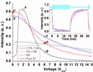
while simultaneously polymerizing the pi cell with a con-stant irradiation of UV light. Subsequently, the transmission/ voltage behavior of the stabilized pi cells is measured by placing their rubbing direction at 45° to the crossed polariz-ers. The driving signal is a 10 kHz square wave and gradu-ally increases from 0 to 15 Vrms. As shown in Fig.4,
consid-ering the conventional driving range of OCB mode TFT-LCD 共2–6 Vrms, square wave兲,4 the intensity operational
range共the difference between the highest to the smallest in-tensity兲 of the original pi cell is 0.525 共AB兲. However, the reason that the OCB mode is conventionally operated with voltages larger than 2 Vrms is to prevent its transition from
the bend state to the twist state. Since the polymerized pi cells have been stabilized in the bend state 共this has been verified by placing the rubbing directions of the pi cells par-allel to the crossed polarizers, which shows no transmission兲, the optical compensation can still work even at 0 Vrms.
Therefore, the driving range of the polymerized pi cells can be further extended from 2 to 0 Vrms. In this case, the
inten-sity operational range of the RB state stabilized pi cell is 0.375共CD兲 while that of the best case of the conventional polymerization stabilized pi cell is 0.25共EF兲.
The response times of the stabilized pi cells are then measured with the same experimental arrangement with a driving signal of a 10 kHz, burst square wave共with 15 ms of 15 Vppand 15 ms of 4 Vpp兲. As shown in the inset of Fig.4,
the switch-on times 共90% to 10%兲 of the pi cells with pure E7, when stabilized in the RB state, and when stabilized with conventional polymerization共the case of 2.5% mesogen兲 are 0.73, 2.44, and 2.42 ms, and the switch-off times 共10% to 90%兲 are 4.4, 8.4, and 6.3 ms. The RB stabilized pi cell has slower response, which results from its less rigid共or say less well-constructed兲 polymer fibril, since the polymerization is executed with dynamic flow.
Although a commercial pi cell is capable of performing with an overall response time of around 3 ms, the LC
mate-FIG. 2.共Color online兲 Experimental setup of the synchronized polymeriza-tion. LD-1 and PD-1 are used to monitor the transmission of the pi cell device. LD-2 and PD-2 are used to trigger the driving signal for pi cell. PD-3 is placed near the pi cell to detect the impingement of UV light on the pi cell. The chopper is used to synchronize the driving signal and the UV light impingement.
FIG. 3.共Color online兲 Oscilloscopic traces of synchronized polymerization. The pi cell is positioned 45° between crossed polarizers.
FIG. 4.共Color online兲 Transmission/voltage behavior of the pi cells. The pi cells are positioned 45° between crossed polarizers. The device conditions are: pi cell with pure E7, 4% mesogen mixed pi cell stabilized in the RB state, 2.5% and 4% pi cells stabilized with conventional polymerization in the stressed bend state. The light source for the measurement is a 5 mW He–Ne laser on 632.8 nm. Inset: response times of the pi cells. The voltage signal is a burst square wave with 15 Vpp for 15 ms and then 4 Vpp for 15 ms.
221109-2 Yang et al. Appl. Phys. Lett. 92, 221109共2008兲
This article is copyrighted as indicated in the article. Reuse of AIP content is subject to the terms at: http://scitation.aip.org/termsconditions. Downloaded to IP: 140.113.38.11 On: Wed, 30 Apr 2014 23:03:32
rial we use here is simply E7, so the response time can be further optimized by using low viscosity LC materials. Moreover, we can increase the switching speed of this pro-posed pi cell by a dual frequency driving method.10,14,15
The difference of the intensity operational range results from the various profiles of LC director after polymeriza-tions. In the case of the pi cell stabilized in the RB state, the LC director throughout the device is stabilized in a more relaxed共i.e., lower tilt兲 state, which thus has higher freedom of switching compared to the pi cell stabilized using the conventional polymerization. To further increase the inten-sity operational range, we have tried to lower the concentra-tion of the reactive mesogen for synchronized polymeriza-tion共it was reported in Ref.7that using lower concentrations results in higher intensity operational range兲, however, using concentrations lower than 4% produces only partial stabili-zation of the bend state.
We have demonstrated a synchronized polymer-stabilization technique, which can be used to stabilize the nonpermanent states in LC devices. In this paper, the nonpermanent RB state which was reported to have high brightness9 is observed and stabilized by our proposed technique. This pi cell stabilized in the RB state has the attributes of high intensity operational range 共an enhance-ment is obtained by a factor of 1.5 compared with the best case of the conventionally polymerized pi cell兲 and feasibil-ity for full dynamic range optical compensation 共no twist state occurs during the device operation兲. This proposed pi cell device could be used with a switching backlight
tech-nique to achieve a complete dark state and lower the power consumption.16
1P. J. Bos and K. R. Koehler-Beran, Mol. Cryst. Liq. Cryst. 113, 329 共1984兲.
2S. T. Wu and A. M. Lackner,Appl. Phys. Lett. 64, 2047共1994兲. 3C. L. Kuo, T. Miyashita, M. Suzuki, and T. Uchida,Appl. Phys. Lett. 68,
1461共1996兲.
4E. J. Acosta, M. J. Towler, and M. D. Tillin,J. Appl. Phys. 97, 093106 共2005兲.
5S. H. Lee, S. H. Hong, J. D. Noh, H. Y. Kim, and D. S. Seo,Jpn. J. Appl.
Phys., Part 2 40, L389共2001兲.
6M. J. Towler and E. P. Raynes, Proceedings of the 22nd International Display Research Conference共Eurodisplay ’02兲, 2002, Nice, France 共un-published兲, Vol. 2, p. 877.
7S. H. Kim and L. C. Chien,Jpn. J. Appl. Phys., Part 1 43, 7643共2004兲. 8F. S. Yeung and H.-S. Kwok,Appl. Phys. Lett. 88, 063505共2006兲. 9K. H. Choi, T.-H. Jung, D. W. Choi, J. E. Park, T. S. Kim, and K. D. Kim,
Proceedings of the Digest of Technical Paper of SID International Sym-posium, 2006共unpublished兲, Vol. 37, p. 713.
10Y. Sun, H. Ma, Z. Li, Z. Zhang, and R. Guan,Appl. Phys. Lett. 90, 091103共2007兲.
11S. R. Lee, J. H. Shin, J. I. Baek, M. C. Oh, T. H. Yoon, and J. C. Kim,
Appl. Phys. Lett. 90, 163513共2007兲.
12C. Y. Huang, R. X. Fung, Y. G. Lin, and C. T. Hsieh,Appl. Phys. Lett.90, 171918共2007兲.
13H. Mori,J. Disp. Technol. 1, 179共2005兲.
14P. D. Brimicombe, L. A. Parry-Jones, S. J. Elston, and E. P. Raynes,J.
Appl. Phys. 98, 104104共2005兲.
15P. Brimicombe, S. J. Elston, and E. P. Raynes, Liq. Cryst. 34, 641共2007兲. 16F. C. Lin, C. Y. Liao, L. Y. Liao, Y. P. Huang, and H. P. D. Shieh, Pro-ceedings of the Digest of Technical Paper of SID International Sympo-sium, 2007共unpublished兲, Vol. 38, p. 1343.
221109-3 Yang et al. Appl. Phys. Lett. 92, 221109共2008兲
This article is copyrighted as indicated in the article. Reuse of AIP content is subject to the terms at: http://scitation.aip.org/termsconditions. Downloaded to IP: 140.113.38.11 On: Wed, 30 Apr 2014 23:03:32