Photonic band gap of two-dimensional triangular photonic crystals with broken
structural and rotational symmetries
K. P. Chang and S. L. Yang
Citation: Journal of Applied Physics 100, 073104 (2006); doi: 10.1063/1.2356992 View online: http://dx.doi.org/10.1063/1.2356992
View Table of Contents: http://scitation.aip.org/content/aip/journal/jap/100/7?ver=pdfcov Published by the AIP Publishing
Articles you may be interested in
Maximum and overlapped photonic band gaps in both transverse electric and transverse magnetic polarizations in two-dimensional photonic crystals with low symmetry
J. Appl. Phys. 106, 063520 (2009); 10.1063/1.3225999
Electrotunable band gaps of one- and two-dimensional photonic crystal structures based on silicon and liquid crystals
J. Appl. Phys. 104, 063108 (2008); 10.1063/1.2975832
Photonic band gaps and planar cavity of two-dimensional eightfold symmetric void-channel photonic quasicrystals
Appl. Phys. Lett. 90, 201111 (2007); 10.1063/1.2739090
Nanostructured-porous-silicon-based two-dimensional photonic crystals Appl. Phys. Lett. 89, 053126 (2006); 10.1063/1.2335586
Slab-thickness dependent band gap size of two-dimensional photonic crystals with triangular-arrayed dielectric or magnetic rods
J. Appl. Phys. 94, 2188 (2003); 10.1063/1.1595709
Photonic band gap of two-dimensional triangular photonic crystals
with broken structural and rotational symmetries
K. P. Chang and S. L. Yanga兲
Department of Electrophysics, National Chiao Tung University, Hsinchu 30050, Taiwan, Republic of China
共Received 14 March 2006; accepted 3 August 2006; published online 9 October 2006兲
Three deformed and two rotational structures are constructed to study the effect of structural and rotational symmetries on the gap widths of E- and H-polarization bands in photonic crystals. The band structures and field patterns of a triangular lattice of hollow tellurium共Te兲 rods are calculated using the plane-wave method. The H-polarization band gaps are strongly affected by the interaction between the fields of the rods as the rods are deformed and affected by the reduction in the rotational symmetry as whole rods are rotated. Only the shapes of the rods affect the E-polarization band gaps as the rods are either deformed or rotated. Moreover, H-polarization modes determine the absolute photonic band gap共PBG兲 width as the rods are rotated, whereas E-polarization modes determine the absolute PBG width as the rods are deformed. © 2006 American Institute of Physics.
关DOI:10.1063/1.2356992兴 I. INTRODUCTION
The physical characteristics of photonic crystals 共PCs兲 and their use in devices have attracted much attention in recent years owing to their various interesting properties and several innovative applications.1–5 Photonic crystals with properly designed dielectric constants, structural symmetry, and filling ratio may have polarization-independent photonic band gaps共PBGs兲, i.e., the so-called absolute PBG.6–9 Abso-lute PBG materials can be used for confining or controlling the propagation of waves.
Some works have demonstrated that the absolute PBGs of two-dimensional 共2D兲 photonic crystals can be widened by reducing the symmetry of the rods; such crystals are typi-cally designed with triangular, square, and hexagonal lattices of air or dielectric rods with various shapes and cross sections.10–14 A hollow oval rod embedded in a triangular lattice can exhibit a large PBG at high normalized fre-quencies.15 However, the effect of structural and rotational symmetries associated with the deformation and rotation of rods on E-polarization共with the electric field parallel to the rods兲 and H-polarization 共with the magnetic field parallel to the rods兲 band gaps of the system has not been studied thor-oughly.
This work investigates the effect of structural and rota-tional symmetries on the E-polarization and H-polarization band gaps of hollow rods embedded in a triangular lattice. The plane-wave method is employed to calculate the band structures and field patterns. The symmetry of hollow rods is more complex than that of solid rods because the former can be broken by deforming and rotating inner and shell rods. Three deformed structures, involving inner rod deformation, shell-rod deformation, and whole rod deformation, are con-sidered to explore the effect of structural deformation on the band structures. Two rotational structures—inner rod rotation and whole rod rotation—are introduced to investigate the
effect of rotational symmetry on the band structures. The correlations between the hollow structures and PBGs can be reasonably explained, and the scattering mechanisms are sys-tematically examined.
II. THEORY
Figure1displays the geometry of the 2D triangular lat-tice of hollow oval rods, where a is the latlat-tice constant, a1 = a共1,0兲, and a2= a共1/2,
冑
3 / 2兲 are the basic vectors of thetriangular lattice. Each hollow rod comprises an inner rod 共hollow portion兲 with isotropic dielectric constant r, and an
outer shell with anisotropic dielectric constants e and o.
The structured background is homogeneous with dielectric constant b. The dimensions of the inner rod and the outer
shell are, in units of lattice constant a and in the directions of the major and minor axes,共ᐉ1, w1兲 and 共ᐉ2, w2兲, respectively.
The terms ␣1=ᐉ1/ w1 and ␣2=ᐉ2/ w2 are used for
conve-nience.
The electromagnetic fields in the 2D photonic crystals are given by Maxwell’s equation,
a兲Electronic mail: [email protected] FIG. 1. Schematic configuration of a triangular lattice with hollow oval Terods.
0021-8979/2006/100共7兲/073104/6/$23.00 100, 073104-1 © 2006 American Institute of Physics
ⵜ ⫻
冋
1共r兲ⵜ ⫻ H共r兲
册
=2
c2H共r兲, 共1兲
where H共r兲 is the magnetic field, 共r兲 is a position-dependent dielectric constant, is the angular frequency, and c is the speed of light in a vacuum. For periodic systems, the magnetic field H共r兲 and the dielectric function 共r兲 can be expressed as sums of plane waves,
H共r兲 =
兺
G =1,2兺
hG,eˆei共k+G兲·r 共2兲 and 共r兲 =兺
G 共G兲eiG·r, 共3兲where hG,is a coefficient of the H component, k is the wave
vector in the Brillouin zone, and G is the reciprocal-lattice vector, respectively. Two independent polarizations charac-terized by the unit vectors eˆ共=1,2兲 are perpendicular to the propagation vector共k+G兲. Under Fourier transform, the coefficient of共G兲 is defined as
共G兲 = 1
Acell
冕
cell共r兲e−iG·rdr, 共4兲
where Acellis the area of the primitive cell of the lattice. So Eq.共1兲 can be expressed in a matrix form,
兺
G⬘ 兩k + G兩兩k + G⬘
兩冋
eˆ2·G,G⬘ −1 · eˆ2⬘
− eˆ2·G,G⬘ −1 · eˆ1⬘
− eˆ1·G,G⬘ −1 · eˆ2⬘
eˆ1·G,G⬘ −1 · eˆ1⬘
册
⫻冋
h1,G⬘ h2,G⬘册
= 2 c2冋
h1,G h2,G册
, 共5兲 where G,G⬘
−1=−1共G−G
⬘
兲 represents the inverse of the ma-trix 共G−G⬘
兲. The eigenvalue equation 共5兲 can then be solved using matrix diagonalization technique.The dielectric constant of hollow structure can be ex-pressed as
共r兲 = b+共e,o−b兲Sshell共r兲 + 共r−b兲Srod共r兲, 共6兲
where Sshell共r兲 and Srod共r兲 are the functions of the outer shell and the inner rod, respectively. The magnitudes of these two functions are set to unity inside the interesting region and zero outside. The Fourier transform of共r兲 is
共G兲 = b␦G,0+共e,o−b兲 2fshell
冑
g2共2兲ᐉ2J1共冑
g2共2兲ᐉ2兲 +共r−b兲 2frod冑
g1共1兲ᐉ1 J1共冑
g1共1兲ᐉ1兲. 共7兲The second and third terms represent共G兲 for the shell and the inner rods, respectively. The factors fshell=共ᐉ2w2兲/Acell
and frod=共ᐉ1w1兲/Acellare the ratios of the area of the outer
shell and of the inner rod to the area of a primitive unit cell.
J1is the Bessel function of the first kind. The function g1共1兲
represents the magnitude of the reciprocal-lattice vector as inner rods are rotated through an angle1, and the function
g2共2兲 represents the magnitude of the reciprocal-lattice
vec-tor as the outer shells are rotated through an angle2. They
are given by g1,2共兲 = Gx 2共cos2 1,2+␣1,2 −2 sin21,2兲 + Gy2共sin21,2+␣1,2−2 cos21,2兲 + 2GxGysin1,2cos1,2共1 −␣1,2 −2兲, 共8兲
where Gx and Gy are the x- and y-axial components of G,
respectively. The band structures for such anisotropic photo-nic crystals can be calculated in the same way as for isotro-pic crystals. In this study, 1000 plane waves were adopted, and the computational errors in the E- and H-polarization modes for each case were estimated to be less than 1%.
III. RESULTS AND DISCUSSION
This study calculates photonic-band structures of hollow tellurium 共Te兲 rods in a triangular lattice. The hollow rods with cross section in the size of micrometers could be pat-terned with the nanolithographic technology. However, Te is not the popular material for the current lithographic technol-ogy; it is still not well developed for making Te microstruc-tures to photonic crystals. The usage of Te in this study is taking advantage of its high refractive index. The high index of refractivity allows us to tune the absolute PBG within a large extent. Furthermore, the large difference between the extraordinary and the ordinary refractive indices also permits us to study more flexibly the effects of the structural and rotational symmetries on the PBG of hollow structure. Te has anisotropic optical properties with approximate extraordinary refractive index ne= 6.2 and ordinary refractive index no
= 4.8 in the wavelength regime between 3.5 and 14m.15–17 The absorption coefficient of Te in the infrared region is less than 1 cm−1.18 In the appropriate infrared range and for a photonic crystal with limited size, the refractive indices of Te can be treated as constants and the absorption effect can be neglected in the calculation.15,16In fact, a preliminary calcu-lation shows that very small uncertainty involved in our cal-culation when the refractive indices of Te is assumed as con-stants and the absorption effect is neglected. The axis of Te rod is set to be parallel to the extraordinary axis and provides different refractive indices for the E- and H-polarization modes in the structure. The band gaps of two modes are overlapped to give the absolute PBG width of the photonic crystal system.
The dielectric constants of the background material and the inner holes are set to b=r= 1. Three deformed
struc-tures, A, B, and C, are considered to investigate the effect of the shape of a hollow rod on the PBG. The structures are deformed by altering the factors ␣1 and ␣2, which are
de-signed to prevent overlap between nearest neighboring rods. The optimal parameters of major axes of inner rods and outer shells, taking as ᐉ1= 0.27a and ᐉ2= 0.48a, are adopted
throughout the simulation to study how the structural and rotational symmetries affect the PBG of hollow structure. Basically, the choice ofᐉ1= 0.27a andᐉ2= 0.48a provides us
eclectically the largest two absolute PBG widths. And both absolute PBG widths decrease with increasingᐉ2 for a
con-stantᐉ1 but fluctuate with varyingᐉ1 for a constantᐉ2.
073104-2 K. P. Chang and S. L. Yang J. Appl. Phys. 100, 073104共2006兲
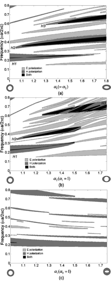
Structures A are designed such that the lengths of the minor axes of the inner and shell rods are simultaneously reduced to equalize␣1 and␣2. Figure2共a兲presents the
de-pendence of the gap map on ␣1. Many gaps appear for
E-polarization modes, and three gaps appear for
H-polarization modes between 0.2 and 0.8共a / 2c兲. The
width of the H1 gap is maximal at ␣1= 1, and is zero at approximately␣1= 1.7. H2 and H3 gaps do not appear in the
hollow circular structure, until structural symmetry is bro-ken. As shown in the diagram, this configuration generally has three absolute PBGs and the E-polarization modes domi-nate the absolute PBG widths.
Structures B with circular inner rods共␣1= 1兲 and
verti-cally deformed shell rods are considered. That is, the struc-tural symmetry of the inner rod is retained, whereas that of the shell rod is broken. Figure2共b兲presents the calculations. When␣2 exceeds 1.35, the gap widths of the E-polarization
modes vary more than those in structures A, drastically re-ducing the absolute gap widths. However, the width of the
H-polarization gap as a function of ␣2 is quite similar to
those in structures A. The width of the H1 gap declines while that of the H3 gap increases as␣2increases. The behavior of the H3 gap width can be elucidated by wave scattering in the hollow rods. The propagation of light of short wavelength in the hollow rods depends strongly on the shape of rod, so resonance can be easily produced. Therefore, the shape of the rod determines the high-frequency gaps of H-polarization modes. With respect to the H1 gap, light with long wave-length cannot easily be trapped with resonance in the rods, so the interaction among the fields of the rods must be exam-ined in detail. In the H-polarization modes, fields are ori-ented in the x-y plane and the tangential fields that connect nearest-neighboring rods must be forced to penetrate regions of air to satisfy the continuity boundary condition.19 Accord-ingly, the variation in the y-directional length influences the fraction of energy in the dielectric regions, and thereby alters the low-frequency gap width.
Structures C have circular shell rods 共␣2= 1兲 and
de-formed inner rods. The air-space sizes between the rods are very thin in such structures. As shown in Fig.2共c兲, the width of the H1 gap is almost independent of␣1, because the air-space sizes among the rods are kept invariable, while the width of the H3 gap varies drastically, since the rods are deformed. Furthermore, the width of the E-polarization gap may not be increased by reducing the structural symmetry of the inner rods, so no absolute PBG is present in such struc-tures.
The calculated band gaps of structures A, B, and C show that the E-polarization modes dominate the absolute PBG widths. The field patterns of each structure are examined to investigate the effect of structural symmetry on the
E-polarization modes. Figures 3共a兲–3共d兲show the level dis-tribution of the displacement field in hollow circular struc-tures and deformed strucstruc-tures A, B, and C, respectively. Each figure plots the distribution of magnitudes of the displace-ment field associated with the seventh band at the
K-symmetry point. The fields in structure A are concentrated
in the dielectric regions for all␣1共=␣2兲 values. However, the
deformation in the shell rods of structure B strongly influ-ences the field distribution. In particular, the displacement fields in the thin section are expelled from the dielectric re-gion and are distributed nonuniformly within the rods, so the gap widths in the E-polarization modes of structure B vary
FIG. 2. Gap maps of共a兲 structure A,␣1=␣2,共b兲 structure B,␣1= 1; and共c兲 structure C,␣2= 1. The major-axis lengths of shell and inner rods are fixed toᐉ1= 0.27a andᐉ2= 0.48a.
more than those of structure A. Figure3共d兲 shows the field patterns in structure C. The variation in the field distribution is not as strong as that in structure B as the geometry of the rods is changed. This result may be attributed to the fact that the sizes of the inner rods are not large enough and the field distribution is similar to that in the hollow circular structure. The symmetry of the hollow structure can also be broken by rotating the inner and shell parts without changing the geometric parameters. Two rotations, inner and whole rod rotations, under the geometric parameter constant␣1=␣2, are
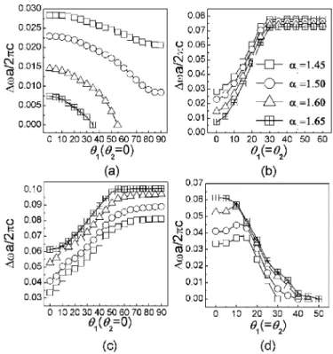
considered herein. All structures have the same filling frac-tion but are differently orientated with respect to the triangu-lar lattice. The inner rod rotation is rotated with a period of 90°, while the whole rod rotation is rotated with a period of 60°. The dependence of the H-polarization gap widths on rotating angle is examined. Figures 4共a兲 and4共b兲 show the H1 gap widths associated with inner and whole rod rotations for various ␣1. The width of the H1 gap slightly decreases
under the inner rod rotation as the angle of rotation increases. Notably, the air-space sizes among the rods remain constant under the inner rod rotation through an arbitrary angle, indi-cating that the interaction between the fields of the rods af-fects the H-polarization modes almost equally at any angle of rotation. At whole rod rotation drastically increases the width of the H1 gap; the gap width is largest at approximately 1 = 30°. These results are attributable to the strong interactions
among the rods and the reduction in the rotational symmetry. Figures 4共c兲and 4共d兲 plot the H3 gap width for inner and whole rod rotations, respectively. As shown in the diagrams, the gap width associated with the inner-rod rotation increases with the rotating angle, but that associated with the whole rod rotation approaches to zero at around 1=2= 40°. The
results associated with the inner rod rotation are governed mainly by the shape of the rod, and those associated with the whole rod rotation are governed by the angle of rotation.
Figure 5 plots the E-polarization gap width at ␣1=␣2
= 1.6 as a function of rotating angle. The gap widths in E1 共between the seventh and eight bands兲 and E2 共between the
ninth and tenth bands兲 vary slightly with the rotation of the whole rod, but vary markedly with the rotation of the inner rod. These results may also be understood by considering the field distribution within the hollow oval rods. Figures 6共a兲
and 6共b兲 plot the amplitude of the displacement field with inner rod rotation and whole rod rotation through an angle of 30°. The field distribution in the whole rod rotation is iden-tical to that in Fig. 3共b兲 because the shapes of the hollow oval rods do not change, so the H-polarization gap widths are almost the same at all angles of rotation. Moreover, the num-ber of nodal planes associated with inner rod rotation almost
FIG. 3. Displacement-field distribution of E-polarization modes inside the hollow rods in the共a兲 hollow circular structure,␣1=␣2= 1,共b兲 structure A with␣1=␣2= 1.6,共c兲 structure B with␣1= 1,␣2= 1.6; and共d兲 structure C with␣1= 1.6,␣2= 1 at K-symmetry point.
FIG. 4. Gap widths as a function of rotating angles1and2for inner rod and whole rod rotations with various␣1共=␣2兲. H1 gap width for 共a兲 inner rod rotations,2= 0, and共b兲 whole rod rotations,2=1; H3 gap width for 共c兲 inner rod rotations, 2= 0, and 共d兲 whole rod rotations, 2=1. Each curve in the same line style in 共a兲, 共c兲, and 共d兲 corresponds to the same quantity of␣1as the list inserted in共b兲.
FIG. 5. E1 and E2 gap widths as a function of rotating angle1for inner rod and whole rod rotations at␣1=␣2= 1.6.
073104-4 K. P. Chang and S. L. Yang J. Appl. Phys. 100, 073104共2006兲
equals that associated with whole rod rotation. However, the fields in the thin dielectric regions are expelled from the dielectric region when the inner rods are rotated, strongly influencing the E-polarization band structures. Interestingly, the shapes of individual rods dominate the E-polarization band structures,20even though the rotational symmetry of the hollow structure is broken.
Figures 7共a兲 and 7共b兲 plot absolute PBG as a function of angle associated with inner and whole rod rotation at
␣1=␣2= 1.6. The absolute gap widths of the inner rod
rota-tion vary markedly because they are governed by the
E-polarization modes. The absolute gap widths under whole
rod rotation decline as the angle of rotation increases because they are dominated by the H-polarization modes. The prop-erties of the formed absolute PBGs also have the same re-sults for any ␣1共=␣2兲 value.
Our simulation and analysis assume that the height of rods is infinity or much larger than the lattice constant of the 2D crystalline arrays. Practically and macroscopically, if the height of the rods is an order larger than the beam size of perpendicular 共to the rods兲 incident light, the height of rods can be considered as infinity ideally. Microscopically, for the case of perpendicular incidence to the rods, if the height of the rods is an order larger than the light wavelength, the wave phenomena of light can be neglected along the direc-tion of rods and the height of rods can be considered infinity. So for the structures we considered here, the minimal height of the rods should be larger than tens of microns to ensure the calculation results agree well with the results for the ex-act 2D array photonic crystals. For the smaller height of the rods, our analysis and comments would be comparatively applicable or valid until the photonic crystals become criti-cally three-dimensional共3D兲 confined systems.
IV. CONCLUSION
In this work, the plane-wave method is used to calculate the field patterns and the band structure of a triangular lattice of hollow Te rods. Firstly, three deformed structures are de-signed by altering the geometric parameters of rods to inves-tigate the effect of structural symmetry on E- and
H-polarization modes. The results in the H-polarization
modes indicate that the air space among the rods dominates the low-frequency gaps while the shape of the rods affects mainly the high-frequency gaps. The results in the
E-polarization modes indicate a strong relationship between
the shape of the rods and the band gaps, as determined from the field patterns. Two rotations, inner and whole rod rota-tions, are considered with fixed geometric parameters to in-vestigate the effect of rotational symmetry on E- and
H-polarization modes. The effect on the E-polarization mode
for rotational structures is similar to that for deformed struc-tures. However, H-polarization modes are affected not only by the field distribution among rods but also by the reduction of rotational symmetry. Analyzing the structural and rota-tional symmetry of the hollow structure is useful in under-standing the properties of the formed PBGs and provides a path for designing proper photonic crystal structures with desired PBGs.
ACKNOWLEDGMENTS
The authors would like to thank Professor T. J. Yang and Professor D. S. Chuu for valuable discussion. This work was supported by the National Science Council, Taiwan under Grant No. NSC 94-2112-M-009-001.
1E. Yablonovitch, Phys. Rev. Lett. 58, 2059共1987兲.
2H. Y. Sang, Z. Y. Li, and B. Y. Gu, Phys. Rev. E 70, 066611共2004兲. 3L. D. A. Lundeberg, D. L. Boiko, and E. Kapon, Appl. Phys. Lett. 87,
241120共2005兲. FIG. 6. Displacement-field distribution of E-polarization mode inside the
hollow oval rods for共a兲 the inner rod rotation with1= 30° and2= 0° and 共b兲 the whole rod rotation with1=2= 30° at the K-symmetry point and ␣1=␣2= 1.6.
FIG. 7. Absolute photonic band gap as a function of rotating angle1for共a兲 inner rod rotations and共b兲 whole rod rotations at␣1=␣2= 1.6.
4D. Labilloy et al., Phys. Rev. Lett. 79, 4147共1997兲.
5S. G. Lee, S. S. Oh, J. E. Kim, H. Y. Park, and C. S. Kee, Appl. Phys. Lett.
87, 181106共2005兲.
6X. H. Wang, B. Y. Gu, Z. Y. Li, and G. Z. Yang, Phys. Rev. B 60, 11417 共1999兲.
7N. Malkova, S. Kim, and V. Gopalan, Phys. Rev. B 66, 115113共2002兲. 8M. Plihal and A. A. Maradudin, Phys. Rev. B 44, 8565共1991兲. 9K. Busch and S. John, Phys. Rev. E 58, 3896共1998兲.
10R. Wang, X. H. Wang, B. Y. Gu, and G. Z. Yang, J. Appl. Phys. 90, 4307 共2001兲.
11L. L. Lin and Z. Y. Li, Phys. Rev. B 63, 033310共2001兲.
12R. Hillebrand and W. Hergert, Solid State Commun. 115, 227共2000兲.
13C. M. Anderson and K. P. Giapis, Phys. Rev. B 56, 7313共1997兲. 14N. Susa, J. Appl. Phys. 91, 3501共2002兲.
15T. Pan, F. Zhuang, and Z. Y. Li, Solid State Commun. 129, 501 共2004兲.
16Z. Y. Li, B. Y. Gu, and G. Z. Yang, Phys. Rev. Lett. 81, 2574共1998兲. 17E. D. Palik, Handbook of Optical Constants of Solids共Academic, New
York, 1991兲.
18S. Ades and C. H. Champness, J. Appl. Phys. 49, 4543共1978兲. 19J. D. Joannopoulos, R. D. Mead, and J. N. Winn, Photonic Crystals:
Modeling the Flow of Light共Princeton University Press, Princeton, 1995兲.
20E. Lidorikis, M. M. Sigalas, E. N. Economou, and C. M. Soukoulis, Phys. Rev. Lett. 81, 1405共1998兲.
073104-6 K. P. Chang and S. L. Yang J. Appl. Phys. 100, 073104共2006兲