國 立 交 通 大 學
電子工程學系 電子研究所碩士班
碩
士
論
文
MHP 視訊及圖形子系統
於 Xilinx ML310 平台上之設計與實現
Design and Implementation of
an MHP Video and Graphics Subsystem
on Xilinx ML310 Platform
研 究 生:陳旻弘
指導教授:杭學鳴
博士
MHP 視訊及圖形子系統
於 Xilinx ML310 平台上之設計與實現
Design and Implementation of
an MHP Video and Graphics Subsystem
on Xilinx ML310 Platform
研究生: 陳旻弘
Student: Min-Hong Chen
指導教授: 杭學鳴 博士
Advisor: Dr. Hsueh-Ming Hang
國 立 交 通 大 學
電 子 工 程 學 系
電
子
研
究
所
碩 士 論 文
A Thesis
Submitted to Department of Electronics Engineering & Institute of Electronics College of Electrical and Computer Engineering
National Chiao Tung University in partial Fulfillment of the Requirements
for the Degree of Master In
Electronics Engineering 2006
HsinChu, Taiwan, Republic of China
MHP 視訊及圖形子系統
於 Xilinx ML310 平台上之設計與實現
研究生: 陳旻弘
指導教授: 杭學鳴 博士
國立交通大學
電子工程學系 電子研究所碩士班
摘要
本篇論文主要目的是在Xilinx ML310平台上,配合 Linux 以及 X Window
System 等,發展一個精簡的 MHP 視訊及圖形子系統。MHP (Multimedia
Home Platform)是由 DVB Consortium 於 2003 年所公開訂定的數位電視中介
層軟體之標準,它允許數位電視在接收視訊及音訊的同時,接收並且執行
互動式的應用程式服務。
為了實現 MHP 所訂定的視訊及圖形模型,我們完成了以下的工作項
目。首先我們選定由 Sun 所訂定的 Java ME, Personal Basis Profile 作為 MHP
系統發展的平台,並且將此 Java 平台移植至 Xilinx ML310 平台上。接著我
們將 FFmpeg 所提供的 MPEG-2 解多工器以及 MPEG-2 視訊解碼器獨立出
來,並且將它們與 JMF Lite 整合。最後,我們將上述建立的元件與由
Microwindows 實做的 AWT 系統結合,並且提出一個有效率的視訊及圖形
整合的方法。
我們所提出的 MHP 視訊及圖形子系統提供了 AWT 繪圖以及 JMF 視訊
處理的功能,包括普通視訊播放、區域剪裁、調整縮放、位置放置等等,
它同時也提供視訊及圖形的整合。最後,本論文驗證了在 Xilinx ML310 平
台上發展 MHP 系統的可行性。
Design and Implementation of
an MHP Video and Graphics Subsystem
on Xilinx ML310 Platform
Student: Min-Hong Chen
Advisor: Dr. Hsueh-Ming Hang
Department of Electronic Engineering &
Institute of Electronics
National Chiao Tung University
Abstract
The purpose of this study is to design and implement a simplified MHP (Multimedia Home Platform) video and graphics subsystem on the Xilinx ML310 platform under the Linux and X Window System. MHP is an open DTV middleware standard developed by the DVB Consortium in 2003. It enables the reception and execution of interactive applications with TV programs.
To accomplish our goal of displaying the MPEG-2 video together with the MHP specified graphics models, we have done the following tasks. We choose the Personal Basis Profile of Java ME as the base for developing the MHP video and graphics subsystem and port it to the Xilinx ML310 platform. We extract the MPEG-2 demultiplexer and MPEG-2 video decoder from the FFmpeg libraries and modify and include them into our framework. Then, we also modify the JMF Lite and combine it with the FFmpeg MPEG-2 decoder. Lastly, the build-up of the above items is integrated with the Microwindows-based Java AWT in an efficient way.
The proposed system is able to provide the AWT graphics and the JMF video presentation services, including normal presentation, arbitrary clipping, scaling and positioning of the MPEG-2 video. It also provides video and graphics composition. Finally, an implementation of the designed MHP video and graphics subsystem has been successfully demonstrated on the ML310 platform.
Acknowledgement
I would like to show my sincere appreciation to my advisor, Professor
Hsueh-Ming Hang. Under his guidance, I had a clear direction of my research
topic and I overcame the difficulties encountered in the process of my M.S.
degree. I not only learned in the technical field, but also the active attitude of
research from my advisor. I would also like to sincerely appreciate Professor
Chun-Jen Tsai. He gave me many suggestions about the design and
implementation.
I am also very willing to thank all the members of the Communication and
Digital Signal Processing Lab, especially Dr. Feng-Cheng Chang. I learned a lot
from his knowledge and experience of system development. The kindness of
everyone in our Lab made me have a colorful and memorable time in the past
two years.
Finally, I dedicate this volume to my family: my parents, my grandparents,
and my brothers. Their support and encouragement helps me to focus on my
research and study without distraction.
Table of Contents
中文摘要 ---
iAbstract
---
iiAcknowledgement
---
iiiTable of Contents
---
ivList of Tables
---
viList of Figures
---
viiiChapter 1 Introduction
---
1Chapter 2 Background
---
32.1 Digital TV Overview --- 3
2.2 Digital Video Broadcasting --- 3
2.3 Multimedia Home Platform --- 4
2.3.1 Architecture of MHP --- 5 2.3.2 MHP Platform Profiles --- 6 2.3.3 DVB-J Application Model --- 7 2.3.4 DVB-J Platform API --- 8 2.3.5 MHP Graphics Model --- 9 2.3.6 Extensions to JMF in MHP --- 12
Chapter 3 Development Environment
---
143.1 Objectives --- 14
3.2 Target Platform and Development Tools --- 14
3.2.1 Xilinx ML310 Platform --- 15
3.2.2 TinyX --- 16
3.2.3 Sun Personal Basis Profile Reference Implementation --- 17
3.2.4 Microwindows-Based AWT --- 18
3.2.5 JMF Lite --- 20
3.2.6 FFmpeg --- 24
Chapter 4 Design and Implementation
---
254.1 Modified JMF Implementation --- 25
4.1.1 FFmpeg-Based MPEG-2 Video Decoder --- 27
4.1.2 Video Clipping and Scaling --- 29
4.1.3 Background and Component-Based Player Presentation --- 33
4.2 Video and Graphics Integration --- 33
4.2.1 Original AWT Graphics Architecture --- 34
4.2.2 Modified Graphics Architecture --- 38
4.2.3 AWT Graphics Update --- 39
4.2.4 Background Video Update --- 43
4.2.5 Component-Based Video Update --- 46
4.3 Performance Profiling --- 51
Chapter 5 Conclusion and Future Work
---
55List of Tables
Table 3.1 Java ME Configurations --- 17
Table 3.2 Profiles of CDC --- 18
Table 4.1 Mapping table of FFmpegController and FFmpeg API --- 28
Table 4.2 Profiling results of the execution time of different frame numbers --- 52
Table 4.2 Profiling results of the video scaling time --- 53
Table 4.3 Profiling results of the composition time --- 54
List of Figures
Figure 2.1 MHP architecture --- 5
Figure 2.2 MHP system block diagram --- 6
Figure 2.3 Xlet lifecycle state machine diagram --- 8
Figure 2.4 An example of MHP display stack --- 10
Figure 2.5 Background, video, and graphics pipeline --- 11
Figure 2.6 MHP composition rule --- 12
Figure 3.1 Xilinx ML310 platform high-level block diagram --- 15
Figure 3.2 Architecture of the X Window System --- 16
Figure 3.3 Architecture of the original Microwindows --- 19
Figure 3.4 Architecture of Microwindows in Sun PBP 1.0.2 RI --- 20
Figure 3.5 Class diagram of JMF Player --- 21
Figure 3.6 State transition diagram of JMF Controller --- 22
Figure 3.7 Architecture of JMF Lite --- 23
Figure 4.1 Architecture of the modified JMF implementation using FFmpeg --- 26
Figure 4.2 Class diagram of the modified JMF implementation using FFmpeg ---- 26
Figure 4.3 Sequence diagram of the modified JMF implementation using FFmpeg 27 Figure 4.4 Flowchart of the MPEG-2 demultiplexing and decoding using FFmpeg 29 Figure 4.5 Process of video format conversion --- 30
Figure 4.6 Process of the modified video format conversion --- 31
Figure 4.8 Architecture of the original AWT of Sun PBP 1.0.2 RI --- 34
Figure 4.9 An example of AWT graphics update --- 37
Figure 4.10 Pseudo code of AWT graphics update --- 38
Figure 4.11 Modified graphics architecture --- 39
Figure 4.12 An example of the modified AWT graphics update --- 42
Figure 4.13 Pseudo code of the modified AWT graphics update --- 43
Figure 4.14 An example of background video update --- 45
Figure 4.15 Pseudo code of background video update --- 46
Figure 4.16 An example of component-based video update --- 49
Figure 4.17 Pseudo code of component-based video update --- 50
Figure 4.18 Scenario of typical EPG usage --- 51
Chapter 1
Introduction
The transition from analog TV to digital TV (DTV) is happening now. Many countries around the world have set a deadline for discontinuing the analog TV broadcasting. Television stations will continue providing both analog and digital services until the deadline. Then, all analog broadcasting will be terminated. DTV is a more advanced technology in that it can provide interactive video/audio and data services, which is not possible by the analog broadcast systems.
Digital Video Broadcasting (DVB) is one of the most widely adopted DTV transmission
standards in the world. The DVB Multimedia Home Platform (DVB-MHP) defines a Java-based platform for developing interactive DTV applications. In addition to providing abstractions for many DVB and MPEG-2 concepts, it defines interfaces for features such as network card control, application download, and layered graphics model, and so on.
A full MHP system is very complicated. It is composed of various functional components. In this thesis, we focus on the video and graphics subsystem. A simplified design to integrate video and graphics is proposed and implemented on a processor-based platform.
This thesis is organized as follows. In Chapter 2, a brief overview of the DTV technology is provided, which includes the DVB standards, the MHP architecture, the MHP programming models, and the graphics model. Chapter 3 describes the objectives of the proposed design, as well as the reference software, and the target environment to develop and deploy the implementation. Chapter 4 describes the limitations of the reference software for developing the video and graphics subsystem. According to these limitations, modifications of
the standard video/graphics system and new functionalities are proposed and implemented. Several profiling results are also provided at the end of this chapter. Based on these results, a discussion of the execution time performance of the MHP video and graphics subsystem is provided. Chapter 5 includes the conclusion remarks and a few possible future work items.
Chapter 2
Background
2.1
Digital TV Overview
Digital television (DTV) is an advanced broadcasting technology. By transmitting the video and audio information in digital format, such as the MPEG-2 Transport Stream (MPEG-2 TS), a digital broadcaster can deliver information more efficiently than an analog broadcaster can do.
By taking advantage of the digital data compression techniques, the conventional 6-MHz bandwidth for an analog channel can carry 4 to 6 digital standard-definition television (SDTV) channels or one high-definition television (HDTV) channel. An SDTV program has similar quality to the best TV pictures in an analog broadcast system and an HDTV program has higher resolution for dramatically better picture and sound quality than what is available in an analog broadcast system.
DTV technologies can be used to provide interactive services with TV programs. This interactivity would introduce various types of pay-per-view services as well as new possibilities for Electronic Program Guide (EPG), home-shopping, and interactive television shows.
2.2
Digital Video Broadcasting
Digital Video Broadcasting (DVB) is a suite of open standards for DTV transmission
terrestrial television, or terrestrial television for handhelds, as defined by the standards of
DVB-S, DVB-C, DVB-T, and DVB-H, respectively. These standards define the physical layer
and the data link layer of a distribution system. DVB systems have been adopted in most of the European, Asian and South American countries.
DVB has two major competitive standards, the Advanced Television Systems Committee (ATSC) and the Integrated Services Digital Broadcasting (ISDB). Most countries in the world adopted the DVB standards. Some other countries adopted ATSC, including the U.S., Canada, Mexico and South Korea. ISDB is developed by Japan for digital television and digital audio broadcasting.
The Ministry of Transportation and Communication (MOTC) of Taiwan originally considered ATSC in 1997. However, over-the-air TV broadcasters and manufacturers tended to adopt DVB, because it is superior in mobile reception, indoor reception and less interference by obstacles in metropolises. In June 2000, the MOTC of Taiwan adopted the DVB-T standard for DTV broadcasting.
In the DVB structure, each MPEG-2 Transport Stream is known as a multiplex. Within a multiplex, each group of elementary streams that makes up a single TV channel is called a
service or a program. Each TV show in a service is known as an event. An MPEG-2 Transport
Stream physically groups a set of services together, but services in DVB systems can also be logically grouped as well. A logical group of services is called a bouquet. A set of MPEG-2 Transport Streams that share some common service information is called a network.
2.3
Multimedia Home Platform
Multimedia Home Platform (MHP) [1] is an open middleware standard developed by the
DVB Consortium in 2003. It is a technical solution for the DTV receiver, which enables the reception and presentation of applications in a vendor, author and broadcaster neutral framework. Applications from various service providers will be interoperable with different MHP implementations in a horizontal market, where applications, networks, and MHP
terminals can be made available by independent providers. The various aspects of an MHP system are described in the following sections.
2.3.1
Architecture of MHP
A full MHP system is composed of three layers as shown in Figure 2.1. The resources layer is a collection of hardware devices and basic software, including the tuner, demultiplexer, media decoder, graphics subsystems, I/O devices, processor, memory subsystem, operating system, and so on. The system software layer provides an abstract view of the resources to MHP applications. This middle layer separates MHP applications from specific hardware and operating system, hence enables the portability of MHP applications. An important component of the system software is the application manager, also known as a
navigator, which is responsible for managing the lifecycle of all MHP applications. MHP
applications implement interactive services as software running on an MHP system. The applications are written to the MHP APIs provided by the system software. [1, pp.42]
Figure 2.1 MHP architecture Source: [1, Figure 4, pp.42]
Figure 2.2 shows the various components that compose a full MHP system, and the interface between an MHP system and MHP applications. MHP applications use the MHP API, which is shown as the bold border enclosing the applications in Figure 2.2, to access the
actual resources of an MHP system. The components comprising a full MHP system can be categorized into the following groups:
Service information and selection, including the tuner, CA subsystem, demultiplexer, DVB service information, CA control, and tuner control.
Data access, including the MPEG-2 section filter, DSM-CC, storage media control, and IP over the return channel.
Presentation, including media control, media decoder, user interaction, graphics, and integration of video and graphics.
Figure 2.2 MHP system block diagram Source: [1, Figure 6, pp.45]
2.3.2
MHP Platform Profiles
The MHP specification defines three profiles as part of the specification [1, pp.29] to provide different capabilities of MHP implementations for specific application areas. The three profiles are:
Enhanced Broadcasting Profile: this profile is the most basic profile of the three. Itcombines digital broadcast of audio and video services with downloaded MHP applications to enable local interactivity. It does not need an interaction channel.
Interactive Broadcasting Profile: this profile enables a range of interactive servicesassociated with or independent of the audio-visual services. This profile requires an interaction channel.
Internet Access Profile: this profile is added in MHP 1.1 specification. It is intendedto provide Internet services. It also allows to link between those Internet services and broadcast services.
2.3.3
DVB-J Application Model
The MHP specification defines two application models: DVB-J and DVB-HTML [1, pp.64-68] [2]. Currently, DVB-J is more frequently used than the other. Thus, a brief description of the DVB-J application model will be presented in this section.
DVB-J applications are different from typical Java applications. Instead, they have a lifecycle similar to that of Java applets. The conventional Java application model assumes that only one application is executed in a Java VM. An application has complete control of its lifecycle including terminating the Java VM in which it runs. In the DTV environment, however, several applications may be executed in the same Java VM, similar to that there are multiple Java applets running in the Java VM invoked by the browser.
Because of the similarities between DVB-J applications and Java applets, a DVB-J application is called an Xlet which is defined by the Java TV API. The Java TV API is adopted into the MHP standard to specify the DVB-J application model. The application manager is responsible for starting and stopping Xlets as well as controlling them in other ways.
There are four states in the lifecycle of an Xlet: Loaded, Paused, Active, and Destroyed. The Xlet state machine model is illustrated by Figure 2.3. When an Xlet has been loaded into memory but not initialized yet, it is in the Loaded state. After the Xlet has
been initialized successfully, or after the return of the invocation of Xlet.pauseXlet() on an Active Xlet, it transitions to the Paused state. An Xlet in the Paused state should minimize its usage of resources. An Xlet enters the Active state from the Paused state after the Xlet.startXlet() method returns successfully. An Xlet is functioning and providing service when in the Active state. An Xlet enters the Destroyed state from any other state when Xlet.destroyXlet() method returns successfully. A Destroyed Xlet releases all of its resources and is terminated.
Loaded Paused Active Destroyed destroyXlet() initXlet() startXlet() pauseXlet() destroyXlet() destroyXlet()
Figure 2.3 Xlet lifecycle state machine diagram Source: [1, Figure 11, pp.66]
2.3.4
DVB-J Platform API
The DVB-J platform [1, pp.104] [3] is an environment on which DVB-J applications are executed, which includes a Java VM and a set of Java class libraries that implement the MHP API. The MHP API has its roots in a number of other standards. On the one hand, the MHP standard is designed to be interoperable with existing standards, and on the other hand, the integration approach avoids re-inventing the wheel. The MHP API is composed of the following APIs:
Java Platform 1.1 API: it is the most basic API that all the other APIs are built on top of. It is also known as the PersonalJava Application Environment (PJAE). Java Media Framework (JMF) 1.0 API: it supports broadcast media presentation
and control.
Java TV 1.0 API: it provides service and service information access, broadcast pipeline control, broadcast data access, and application lifecycle management. Home Audio Video Interoperable (HAVi) 1.1 Level2 User Interface API: it defines
the MHP graphics model and a Java-based user interface solution suitable for consumer device display.
Digital Audio Visual Council (DAVIC) 1.4 API: it provides low-level APIs for MPEG concepts and resource management.
Java Secure Sockets Extension (JSSE) 1.0.2 API: it supports security management. DVB core API: it provides various extension APIs to those aforementioned APIs.
2.3.5
MHP Graphics Model
The MHP graphics model [1, pp.197-204] is defined by the HAVi 1.1 API. Each screen connected to an MHP receiver has three kinds of planes. They are, from back to front, a background plane, one or more video planes, and one or more graphics planes. Figure 2.4 shows an example of the MHP display stack.
A background plane is represented by an instance of HBackgroundDevice and is capable of displaying single solid color, a still image, or a video drip, depending on the capability of the MHP receiver.
An MHP application can control MPEG-2 video on the video plane outside the AWT hierarchy. Multiple video planes may be supported to provide features like picture-in-picture if there are multiple MPEG-2 video decoders. A video plane is represented by an instance of HVideoDevice.
draw objects, including component-based videos, user interface components, and graphical objects. A graphics plane is represented by an instance of HGraphicsDevice.
Figure 2.4 An example of MHP display stack Source: [1, Figure 16, pp.197]
The final display output on the screen is represented by an instance of HScreen, which is the composition of HBackgroundDevice, HVideoDevice, and HGraphicsDevice. The background, video, and graphics pipelines are illustrated by Figure 2.5. It shows that applications have full control over the source of the content that enters the different pipelines. Furthermore, an application can control clipping, scaling and positioning of the content at different stages in the different pipelines.
Background data Video data Graphics data Background decoder Video decoder Graphics composition MPEG video after ETR154 upsampling Scale/ Clip/ Position/ Pan-scan HBackgroundDevice HVideoDevice HGraphicsDevice Background Video Graphics + Screen HScreen Scale/ position Content Processing function Control by application Scale/ position Scale/ position JMF extensions
Figure 2.5 Background, video, and graphics pipeline Source: [1, Figure 22, pp.203]
Figure 2.6 shows the MHP composition rules. There are three steps to compose the final output for display:
Step 1 The graphics components are composed following the traditional AWT graphics model using Porter-Duff rules.
Step 2 The background and video planes are composed using the Porter-Duff rule SRC. The video plane has alpha values of either 0.0 or 1.0.
Step 3 The results are composed together using the SRC_OVER rule with the graphics results as the source and the results of the background/video composition as the destination.
The Porter-Duff rules are alpha composition rules for combining source and destination pixels to achieve blending and transparency with graphics, image, and video. The color and alpha components produced by the composition operation are computed as follows:
= + = + Cd Cs Fs Cd Fd Ad As Fs Ad Fd
, where the abbreviations are used:
Cs: one of the color components of the source pixel. Cd: one of the color components of the destination pixel. As: alpha component of the source pixel.
Ad: alpha component of the destination pixel.
Fs: fraction of the source pixel that contributes to the output. Fd: fraction of the destination pixel that contributes to the output.
Each Porter-Duff composition rule is specified by Fs and Fd. For example, the SRC rule is specified by Fs=1 and Fd=0, which means that the source pixel is copied to the destination and the destination is not used as input. The SRC_OVER rule is specified by Fs=1 and
Fd=(1-As), which means that the source is composed over the destination.
Combines with SRC, SRC_OVER, or CLEAR rules Always combines with SRC_OVER rule Always combines with SRC rule
Figure 2.6 MHP composition rules Source: [1, Figure 24, pp.204]
2.3.6
Extensions of JMF in MHP
component. The MHP specification, however, defines that a video can be presented either on the video plane or on the graphics plane as an AWT component. These two different ways of video presentation result in two kinds of JMF Players, that is, background JMF Player and component-based JMF Player [1, pp.210-213].
A background JMF Player presents video on the video plane independent of the AWT hierarchy. On the contrary, a component-based JMF Player presents video inside an AWT component, and follows the positioning and resizing rules of an AWT component. The video is always scaled to the full size of the component. Support for component-based Players is not mandatory in all MHP profiles.
The MHP specification also defines many Controls that provide a JMF Player with additional functionalities to control the video format conversion, including clipping, scaling, and positioning of a video. These extended Controls related to video format conversion are enumerated as follows:
javax.tv.AWTVideoSizeControl: it supports scaling, positioning, and clipping of a background video in the screen coordinate space.
org.dvb.media.BackgroundVideoPresentationControl: it supports setting and querying of the video presentation for a background Player.
org.dvb.media.VideoFormatControl: it enables applications to get information associated with the format and aspect ratio of the video.
org.dvb.media.VideoPresentationControl: it supports setting and querying the video presentation.
Chapter 3
Development Environment
3.1
Objectives
The objectives of this thesis are to design and implement a video and graphics subsystem conforming to the MHP graphics model in an embedded system environment. The system should provide the following functionalities:
It provides a single background plane, a single video plane, and a single graphics plane.
It supports drawing AWT components and graphics primitives on the graphics plane using the Porter-Duff composition rules.
It supports JMF background MPEG-2 video Player and component-based MPEG-2 video Player.
It supports arbitrarily clipping, scaling, and positioning of an MPEG-2 video. It supports graphics plane and video plane composition using the Porter-Duff
SRC_OVER rule.
The embedded system environment used for deployment is described in the following sections.
3.2
Target Platform and Development Tools
To emulate a resource-constrained DTV set-top box, the Xilinx ML310 platform is chosen as the target environment. The hardware and software configurations are described in
the following sections.
3.2.1
Xilinx ML310 Platform
The Xilinx ML310 platform [4, pp.17] is a prototyping board targeting on the development of embedded system and system-on-chip application. The high-level block diagram of the ML310 platform is shown in Figure 3.1.
Figure 3.1 Xilinx ML310 platform high-level block diagram Source: [4, Figure 2-2, pp.17]
The Virtex-II XC2VP30-FF896 FPGA has two embedded PowerPC 405 processors clocked at 300 MHz maximally. The 512 MB CompactFlash card contains a DOS FAT16 filesystem partition and a Linux EXT3 filesystem partition. The DOS filesystem partition
contains a set of ACE files to run board diagnostics, as well as to demonstrate the operation of various operating systems such as MontaVista Linux, VxWorks, and QNX.
3.2.2
TinyX
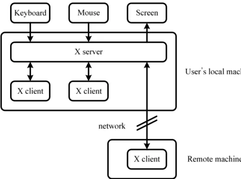
The X Window System [5] [6], also known as X or X11, is a windowing system widely used in the UNIX, Linux, and other UNIX-like operating systems. It is designed as client-server architecture. An X server handles the actual graphics display through direct access to graphics device drivers. It also handles the interaction with users, including reading the mouse and the keyboard events through kernel device drivers. All the information is relayed to X clients in the form of X events. X clients are applications that communicate with an X server by receiving X events and issuing requests.
An X client and an X server communicate with each other through the X protocol delivered over a network on top of TCP/IP or an inter-process communication mechanism. The X protocol provides network-transparency: the X client and server may run on the same machine or on different ones, possibly with different hardware architectures and operating systems. Figure 3.2 illustrates the architecture of the X Window System.
TinyX [7] is an X server implementation included in the MontaVista Linux Professional Edition 3.1 shipped with the Xilinx ML310 platform. It is a stripped-down X server based on XFree86. Specifically, TinyX servers are targeted towards resource-constrained environments. The TinyX communicates with the graphics hardware through the Linux framebuffer device and hence has no hardware acceleration. The MontaVista Linux kernel has a built-in driver for Matrox Millennium II graphics card currently.
3.2.3
Sun Personal Basis Profile Reference Implementation
The Java Platform, Micro Edition (Java ME) provides a runtime environment for Java applications running on resource-constrained consumer and embedded devices. The Java ME is further defined by Configurations and Profiles [8, pp.7-11].
A Configuration is a basic set of APIs and virtual machine features needed to support a certain range of devices. Currently, there are two Java ME Configurations: the Connected
Limited Device Configuration (CLDC) and the Connected Device Configuration (CDC).
Table 3.1 provides a short description for the CLDC and CDC.
Table 3.1 Java ME Configurations
CLDC CDC
Memory
128 KB to 512 KB total memory with <= 256 KB RAM and <= 256 KB ROM
>= 256 KB RAM and >= 512 KB ROM
Java VM KVM. Accommodated to memory
limitation
CVM. Supports full Java virtual machine specification
Target devices
mobile phones and low-end PDAs DTV set-top box, VoIP phones, network printers, routers, residential gateways
Source: [8, Table 2, pp.10]
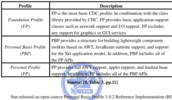
A Profile is an additional set of APIs that support a narrower range of devices. A Profile is built on a specific Configuration. Table 3.2 describes the various CDC Profiles.
platform requirements has completed the End of Life process and is no longer supported by Sun. Personal Profile is positioned as the migration from the PJAE. To address the need of DTV that is less capable than those characterized by Personal Profile, Personal Basis Profile [9] is defined as a subset of Personal Profile which is appropriate for DTV.
Table 3.2 Profiles of CDC Profile Description
Foundation Profile
(FP)
FP is the most basic CDC profile. In combination with the class library provided by CDC, FP provides basic application-support classes such as network support and I/O support. FP excludes any support for graphics or GUI services
Personal Basis Profile
(PBP)
PBP provides a structure for building lightweight component toolkits based on AWT, JavaBeans runtime support, and support for the Xet application model. In addition, PBP includes all of the FP APIs
Personal Profile
(PP)
PP provides full AWT support, applet support, and limited bean support. In addition, PP includes all of the PBP APIs
Source: [8, Table 3, pp.11]
Sun released an open-source Personal Basis Profile 1.0.2 Reference Implementation (RI). The PBP 1.0.2 RI includes a full-featured Java VM called CVM and a set of class libraries supporting CDC 1.0 API, FP1.0 API, and PBP 1.0 API. The AWT of the PBP 1.0.2 RI is implemented using the Microwindows modified by Sun. The original and modified Microwindows will be described in the next section.
3.2.4
Microwindows-based AWT
Microwindows [10] is an open-source windowing system for resource-constrained
devices. It brings some of the features of modern windowing systems without the over-killed requirements of a typical desktop windowing system, such as the X Window System and the Microsoft Windows. The project was renamed from Microwindows to Nano-X Window
Windows.
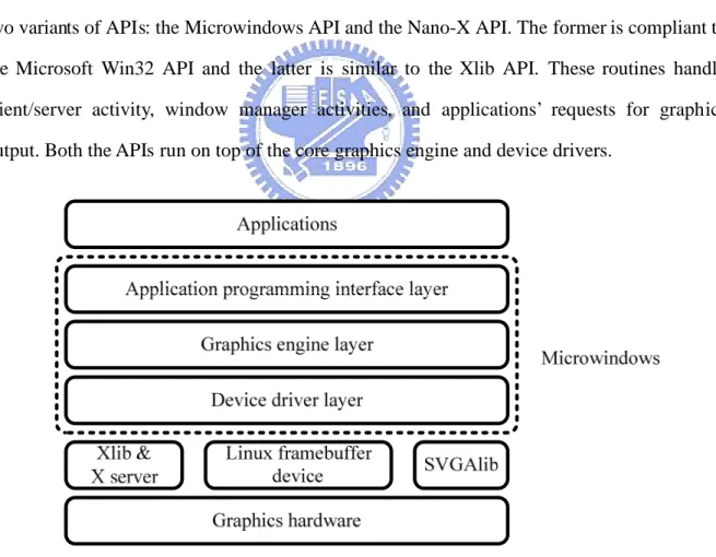
Microwindows has a three-layered design as illustrated in Figure 3.3. The lowest layer is the device driver layer. A typical implementation of Microwindows links at least one screen, mouse and keyboard driver into the system. This layer provides a uniform interface to perform the hardware-specific operations. This design allows various hardware devices to be added to Microwindows without affecting the way the entire system works
The middle layer is the device-independent graphic engine. It provides the core graphics functionalities which invoke the screen, mouse and keyboard drivers to communicate with the hardware. User applications must never call the core graphics engine routines directly, but rather through the application programming interface layer.
The top layer is the application programming interface layer. Microwindows supports two variants of APIs: the Microwindows API and the Nano-X API. The former is compliant to the Microsoft Win32 API and the latter is similar to the Xlib API. These routines handle client/server activity, window manager activities, and applications’ requests for graphics output. Both the APIs run on top of the core graphics engine and device drivers.
Figure 3.3 Architecture of the original Microwindows
Sun made a lot of modifications on Microwinodws to make it work in the Sun PBP 1.0.2 RI. The modified Microwindows architecture is shown in Figure 3.4. Only X11 screen device
driver is supported and the API layer is modified significantly. Neither the Microwindows API nor the Nano-X API is supported because the Java AWT API plays the same role as they do. Sun replaced the original API layer by the Microwindows AWT layer to link the Java AWT API against the Microwindows graphics engine.
Graphics hardware Xlib & X server Virtual framebuffer Framebuffer driver X11 driver Graphics engine
Microwindows AWT (native side) Microwindows AWT (Java side)
Java AWT Java applications
Microwindows
Figure 3.4 Architecture of Microwinodws in Sun PBP 1.0.2 RI
3.2.5
JMF Lite
Java Media Framework (JMF) is an API for incorporating time-based media into Java
applications. The Java TV and MHP API both rely on the JMF API to control audio and video media streams. Figure 3.5 shows the class diagram of a JMF Player.
Figure 3.5 Class diagram of JMF Player
On the top of the class hierarchy is the Clock interface. A Clock contains a TimeBase that keeps a time-based time tracking the passage of time much like a crystal oscillator. A Clock itself keeps the current position within a media stream called media time. Clockdefines two states: Stopped and Started. A Clock’s media time is running and synchronized to the time-base time when in the Started state. When in the Stopped state, the media time is stopped and not synchronized to the time-base time.
Controller extends Clock and provides additional functionalities such as resource allocation, event generation, and a mechanism for obtaining additional Controls attached to a Controller. Controller subdivides Clock’s Stopped state into five resource allocation phases: Unrealized, Realizing, Realized, Prefetching, and Prefetched. The state transition of a Controller is shown in Figure 3.6.
When a Controller is instantiated, it is in the Unrealized state. An Unrealized Controller does not have enough information and resources to be useful to control media. When Controller.realize() is invoked to make a transition to the Realized state, it goes through the transient Realizing state. A Realizing Controlleris in the process of preparing to acquire the information and resources needed to present media. Once a Controller moves to the Realized state, it acquires all the resources needed except for those that may imply exclusive use of a scarce system resource,
such as the MPEG-2 video decoder hardware. Unrealized Realizing Realized Prefetching Prefetched Started realize() Posts RealizeCompleteEvent prefetch() Posts PrefetchCompleteEvent syncStart(), Posts StartEvent deallocate() , Posts DeallocateEvent deallocate() , Posts DeallocateEvent stop(), Posts StopEvent
Figure 3.6 JMF Controller state transition diagram
When Controller.prefetch() is invoked, a Realized Controller will make a transition to the Prefetched state through the transient Prefetching state. A Controller is said to be in the Prefetching state when it is in the process of performing some critical tasks to minimize the startup latency, such as to acquire scarce hardware resources, to fill buffers with media data, or to perform other start-up processing. When finished, a Controller moves to the Prefetched state. Once a Controller is Prefetched, it is capable of starting as quickly as possible.
There are two variants of state transition methods which can induce state changes. The forward transition methods, including realize(), prefetch(), and syncStart(), are executed asynchronously and return immediately. When the requested operation is complete, a Controller posts a ControllerEvent indicating that the target state has been reached. The backward transition methods, including stop() and deallocate(), can induce a transition back to a previous state. These methods are executed synchronously.
By JMF specification, “a Control is an object that provides a way to affect some aspects
of a Controller’s operation in a specific way”. The advantage of Control interface is that it
affords Controller extended functionality without having to create a subclass. For instance, Controls are typically used to provide functionalities such as volume control, audio and subtitle language choice, or video format conversion control.
A MediaHandler is responsible for reading and managing media content delivered from a DataSource and it always has exactly one DataSource attached to it. The DataSourceabstracts the media protocol-handlers.
Playeris a MediaHandler for presenting and controlling time-based media. It also extends the Controller and Duration interfaces. It relaxes some restrictions that a Controller imposes on what methods can be called when the Controller is in a particular state. Player also provides ways to manage a group of Controllers and to obtain AWT components associated with it.
JMF Lite [11, pp.18] is a JMF implementation included in Sun Java TV 1.0 Reference Implementation. It is designed in two layers: a cross-platform porting layer and a platform-specific layer. The former is responsible for matching content with players and managing those players and the latter includes an MPEG-2 video decoder and renderer based on Microsoft Active Movie. The JMF Lite architecture is shown in Figure 3.7.
3.2.6
FFmpeg
FFmpeg [12] is a set of open-source and cross-platform libraries for multimedia applications. It consists of the following components:
ffmpeg: a command line transcoding tool.
ffserver: a multimedia streaming server for live broadcasts over HTTP or RSTP. ffplay: a simple media player based on SDL and other FFmpeg libraries.
libavcodec: a library containing all video/audio encoders and decoders that are used by FFmpeg.
libavformat: a library containing all demultiplexers and multiplexers that handle the file formats used by FFmpeg. Several URL protocol handlers are also included in this library.
Chapter 4
Design and Implementation
4.1
Modified JMF Implementation
According to the MHP specification, a JMF implementation must provide the following functionalities:
Extracts the video stream from an MPEG-2 Transport Stream Decodes the MPEG-2 video stream
Clips and scales the decoded video
Although the JMF Lite included in the Sun Java TV 1.0 RI can meet the first two requirements in the Microsoft Windows environment, the adoption of the proprietary Active Movie library causes it not to be working on the ML310 platform. The first task is to replace the Active Movie library by the open-source FFmpeg libraries, and port the JMF Lite to the ML310 platform.
The MPEG-2 demultiplexer and the MPEG-2 video decoder in the modified JMF implementation are based on the libavformat and libavcodec library of FFmpeg, respectively [13]. The architecture of the modified JMF implementation is illustrated by Figure 4.1. Because of the two-layered design of JMF Lite, the cross-platform porting layer can be left unaffected.
JMF application
Porting layer
FFmpeg-based MPEG -2 player (Java side)
FFmpeg-based MPEG-2 player (native side)
libavcodec
JMF API
FFmpeg API libavformat
Figure 4.1 Architecture of the modified JMF implementation using FFmpeg
TimeBase Clock Controller Player SystemTimeBase MediaClock MediaController MediaPlayer FFmpegController (Java side) Handler (MPEG-2 player) FFmpegController (native side) libavformat libavcodec
Figure 4.2 Class diagram of the modified JMF implementation using FFmpeg
Figure 4.2 shows the class diagram of the modified JMF implementation. The design is developed on the original JMF Lite architecture. The left column, including TimeBase, Clock, Controller, and Player, are part of the JMF API. The middle column, including SystemTimeBase, MediaClock, MediaController, and MediaPlayer, are part of the JMF Lite porting layer. The right column, including Handler and FFmpegController, are implemented based on the FFmpeg API and the ML310 platform.
4.1.1
FFmpeg-Based MPEG-2 Video Decoder
Figure 4.3 illustrates the sequence diagram of the modified JMF implementation. A JMF application calls realize(), prefetch(), and start(), to make a Player change state forwardly. The state transition operations are accomplished by calling doRealize(), doPrefetch(), and doStart(), on FFmpegController, respectively. The FFmpeg APIs mapped to the FFmpegController invocations are listed in Table 4.1
realize() RealizeCompleteEvent prefetch() PrefetchCompleteEvent start() StartEvent EndOfMediaEvent doRealize() doPrefetch() doStart()
FFmpeg API calls mapped to realize()
listed in Table 4.1
FFmpeg API calls mapped to start()
listed in Table 4.1 FFmpeg API calls mapped to prefetch()
listed in Table 4.1 Application JMF Lite
porting layer FFmpegController FFmpeg
Table 4.1 Mapping table of FFmpegController and FFmpeg API FFmpegController FFmpeg API
doRealize av_open_input_file av_find_stream_info avcodec_find_decoder avcodec_open avcodec_alloc_frame avpicture_fill doPrefetch None doStart av_read_packet avcodec_decode_video img_convert doDeallocate av_free avcodec_close av_close_input_file doClose av_free avcodec_close av_close_input_file
The flowchart of MPEG-2 demultiplexing and MPEG-2 video decoding using FFmpeg is illustrated by Figure 4.4. It can be described by the following steps:
Step 1 Checks if there are remaining data bytes in the buffer. If yes, goes to Step 2, otherwise goes to Step 4.
Step 2 Calls FFmpeg avcodec_decode_video() to decode a chunk of data bytes in the buffer. Once the frame data are decoded, they are taken off from the buffer. Then, goes to the Step 3.
Step 3 Determines if a complete frame has been decoded. If yes, terminates this process, otherwise goes to Step 1.
Step 4 Calls FFmpeg av_read_packet() to read a packet from the MPEG-2 Transport Stream. Then determines whether the packet is a video packet or not. If yes, goes to Step 5, otherwise goes to Step 4 again.
Figure 4.4 Flowchart of MPEG-2 demultiplexing and decoding using FFmpeg Source: [13]
4.1.2
Video Clipping and Scaling
After an MPEG-2 video frame is decoded, the JMF implementation then clips and scales it as necessary. For convenience, the decoded frame is stored as an X image using the MIT-SHM extension [5] [6]. To save the memory bandwidth for transferring the frame data, the dimension of the original frame may be smaller than the full-screen size. For example, the dimension of the original frame may be QCIF and the size of a video display device is 720576. Hence, there should be a stretch operation before the frame is actually rendered on the screen.
According to the MHP specifications, the clipping and scaling operations are performed against the full-screen video frame after upsampling [1, pp.203, Figure 22]. The process of the video format conversion is illustrated by Figure 4.5. The major problem of this approach is
that it requires an upsampling operation and a scaling operation which are very time-consuming.
Figure 4.5 Process of video format conversion
In this thesis, a modified approach is proposed to produce a pseudo full-screen video frame instead of a physical one. The clipping and scaling operations are performed directly against the decoded video frame with an appropriate coordinate transformation. The MHP applications continue to make requests of clipping and scaling to the pseudo full-screen video frame because the coordinate transformation is transparent to the MHP API. Figure 4.6 illustrates the process of video format conversion of the proposed approach.
Decoded video Pseudo upsampled full-screen video Clipping region Transformed video on final screen Scaling
Figure 4.6 Process of the modified video format conversion
Figure 4.7 illustrates the coordinate transformation. The dimension of the decoded video frame is Wo Ho and the dimension of the full-screen video frame is WfHf . The clipping region has a dimension of Ws Hs and originates at (Xs Ys, ). The video after clipping and scaling has a dimension of WdHd and is positioned at (Xd Yd, ). A pixel (X1 Y1, ) in the region of the transformed video corresponds to the pixel (X2 Y2, ) in the pseudo full-screen video. The transformation between (X1 Y1, ) and (X2 Y2, ) is as follows:
= +( - ) = +( - ) Ws X2 Xs X1 Xd Wd Hs Y2 Ys Y1 Yd Hd
(X2', Y2') (X2, Y2) (X1, Y1) (Xd, Yd) (Xs, Ys) (Xs’, Ys’) Wf Hf Wf Hf Wo Ho Wd Hd Ws Hs Ws’ Hs’ Decoded video Pseudo upsampled full-screen video Clipping region Transformed video on final screen
Figure 4.7 Coordinate transformation in the modified video format conversion
The clipping region in the pseudo full-screen video is projected from the decoded video. The pixel (X2 Y2, ) in the pseudo full-screen video is projected from the pixel (X2' Y2', ) in the decoded video using the following transformation:
= = Wo X2' X2 Wf Ho Y2' Y2 Hf
Combining these two transformations, the pixel (X1 Y1, ) in the transformed video on the final screen is projected from the pixel (X2' Y2', ) in the decoded video using the following transformation: = ( + ( - ) ) = ( + ( - ) ) Ws Wo X2' Xs X1 Xd Wd Wf Hs Ho Y2' Ys Y1 Yd Hd Hf
Although the modified approach eliminates the upsampling operation, the overhead of coordinate transformation can not be ignored. One of the problems is that the current implementation is written in C language. This could be improved by re-writing it using assembly code. The other problem is that the PowerPC 405 takes 4 and 35 cycles for a multiply and divide operation, respectively. Software multiplication and division can be avoided if the coordinate transformation is implemented using the FPGA or other dedicated hardware.
4.1.3
Background and Component-Based Player Presentation
Presentation of an MPEG-2 video after the video format conversion is not handled by the JMF implementation itself. The video content needs to be composed with the background plane and AWT graphics whether the video is presented using a background Player or a component-based Player. The JMF implementation provides a mechanism for MHP applications to change the video presentation mode. The actual work of presentation is delegated to a functional unit responsible for the composition of the background plane, video content, and AWT graphics. This functional unit will be described in Section 4.2.
4.2
Video and Graphics Integration
The main task of the proposed MHP video and graphics subsystem is focused on how to integrate video and graphics efficiently. First, we explain how the Microwindows-based Java AWT framework works. Then, a graphics model is proposed to overcome the limitations of
the original AWT framework to integrate the video and graphics efficiently.
4.2.1
Original AWT Graphics Architecture
The AWT of the Sun PBP 1.0.2 RI is a lightweight framework, which means that the AWT components do not have native widget toolkit peers except for the top-level container. When an AWT component’s repaint() method is called, the repaint request will be forwarded to its parent containers until it reaches the top-level container. A top-level container is the only heavyweight AWT component which is simply a rectangular drawing region on the native graphics system.
In the Sun PBP 1.0.2 RI, the top-level container is java.awt.Window and its native peer is an X window. Once the repaint request is forwarded to java.awt.Window, an AWT update event is posted and put into the AWT event queue. Later, the AWT event dispatch thread takes the update event off the AWT event queue, and dispatches it to java.awt.Window. The java.awt.Window.update() method is invoked in response to receiving the update event. Inside the update() method, the top-level container first clears the update region by filling it with the container’s background color. Then the top-level container draws all the descendant components clipped by the update region.
Figure 4.8 shows the AWT graphics model. In the Sun PBP 1.0.2 RI, all the graphics operations are performed against the off-screen buffer and then updated to the on-screen X Window. The use of an off-screen buffer is two-fold. One is to reduce the flickers and the other is to provide alpha composition in X11-based environment.
The AWT of Sun PBP 1.0.2 RI is based on the modified Microwindows which runs on top of X11. PBP 1.0 AWT API supports three Porter-Duff composition rules: SRC_OVER, CLEAR, and SRC. When SRC_OVER composition rule is applied, the final pixel value depends both on the source pixel value and the destination pixel value. The alpha composition operation is very time-consuming because it has to be performed pixel-by-pixel. If the alpha composition operation is performed directly to the on-screen X Window, users may notice the pixel-by-pixel flickers which is very annoying. Using the double-buffering technique, the graphics is first drawn on the off-screen buffer and then is blitted to the on-screen X Window all at once.
Moreover, X does not support the transparency and translucency directly. An X Window cannot hold alpha information. Therefore, each time the graphics is drawn to the X Window, the alpha information is dropped. By drawing graphics to the off-screen buffer that has an alpha channel, the alpha information of the graphics can be retained. Thus, the alpha composition can be achieved.
Figure 4.9 illustrates an example of AWT graphics update and Figure 4.10 shows the pseudo code of the process. In this example, there are two AWT components alpha-blended together; one is a rectangle in the back and the other is an oval in the front. An AWT update event is posted when the oval component changes its color. Because X does not support direct alpha-composition, the update process consists of several off-screen operations and on-screen refreshes.
(a) Clears the update region of the off-screen buffer
(b) Draws the rectangular AWT component to the off-screen buffer
(d) Draws the oval AWT component to the off-screen buffer
X Window
Off-screen buffer
Blits off-screen buffer to X Window
(e) Blits the off-screen buffer to the X Window Figure 4.9 An example of AWT graphics update
update() {
The update region is the bounds of the repainted AWT component; Calls clearRect(); paint(); } paint() {
For each child component { Calls paint(); } } repaint() { Forwards to Window.update(); } paint() {
Draws graphics primitives, for example, fills an oval or a rectangle;
}
clearRect () {
Clears the update region // of the off-screen buffer // by filling it with //
background color; // Figure 4.9(a) }
fillOval() {
Draws a filled oval to the // off-screen buffer clipped //
by the update region; // Figure 4.9(d)
Blits the off-screen buffer // to X Window clipped by //
the update region; // Figure 4.9(e) }
fillRectangle() {
Draws a filled rectangle to the off-screen buffer clipped //
by the update region; // Figure 4.9(b)
Blits the off-screen buffer // to X Window clipped by //
the update region; // Figure 4.9(c) }
java.awt.Window
java.awt.Component
Microwindows graphics
Figure 4.10 Pseudo code of AWT graphics update
4.2.2
Modified Graphics Architecture
The AWT of the Sun PBP 1.0.2 RI does not provide the stacked planes such as background plane, video plane, and graphics plane. To present video together with AWT graphics and to alpha-blend the graphics over the video at the same time, the AWT graphics architecture of the Sun PBP 1.0.2 RI is not sufficient. A graphics model is designed to support alpha-blending graphics over video as shown in Figure 4.11.
Figure 4.11 Modified graphics architecture
An X Pixmap [5] [6] is inserted between the X Window and the off-screen buffer. It is an X-specific off-screen resource similar to the off-screen buffer allocated by malloc(). The off-screen buffer plays the role of the graphics plane in the MHP graphics model. All AWT graphics operations are performed against the off-screen buffer as in the ordinary graphics architecture. The X Pixmap is designed to be the composition buffer of the video plane and the graphics plane. When the video content is rendered to the X Pixmap, the AWT graphics in the off-screen buffer is alpha-blended over the video and the result is stored to the X Pixmap. Likewise, once AWT graphics is drawn to the off-screen buffer, it is alpha-blended with the video and the result is stored to the X Pixmap. The X Window represents the final display device. The double-buffering technique is applied with the X Pixmap being the back buffer and the X Window being the primary surface.
As described in Section 4.1.2, the JMF implementation stores the decoded video and the transformed video as X Image structures. The video is rendered to the X Pixmap by a simple XPutImage()call or an XShmPutImage() call when the X Image is allocated in shared memory.
4.2.3
AWT Graphics Update
architecture. Figure 4.12 shows an example of AWT graphics update and Figure 4.13 shows the pseudo code of this process. In this example, there are three components on the screen: a background video in the back, a component-based video in the middle, and a rectangular AWT component in the front. An AWT update event is posted when the AWT component changes color and the update region is the bounds of the AWT component.
X Pixmap X Window
Off-screen buffer Decoded video
Transformed video
Clears update region
(a) Clears the update region of the off-screen buffer
(c) Draws the AWT component to the off-screen buffer
(d) Clears the update region of the X Pixmap
(f) Alpha-blends the off-screen buffer over X Pixmap
(g) Blits X Pixmap to X Window
update() {
The update region is the bounds of the repainted AWT component; Calls clearRect(); paint(); } paint() {
For each child component { Calls paint(); } Calls updateGraphics(); } repaint() { Forwards to Window.update(); } paint() {
Draws graphics primitives, for example, fills a rectangle; }
clearRect() {
Clears the update region // of the off-screen buffer // by filling it with completely //
transparent color; // Figure 4.12(a) }
fillRectangle() {
Draws a filled rectangle to // the off-screen buffer clipped //
by the update region; // Figure 4.12(c) }
updateGraphics() {
Clears the update region // of X Pixmap by filling it //
with background color; // Figure 4.12(d)
Draws background video to // X Pixmap clipped by the //
update region; // Figure 4.12(e)
Alpha-blends the off-screen // buffer over X Pixmap clipped // by the update region, and put //
the result to X Pixmap; // Figure 4.12(f)
Blits the update region of //
X Pixmap to X Window; // Figure 4.12(g) }
java.awt.Window
java.awt.Component
Microwindows graphics Video and graphics integrator
paint() {
Draws component-based // video to the off-screen //
buffer; // Figure 4.12(b) }
VisualComponent
Figure 4.13 Pseudo code of the modified AWT graphics update
4.2.4
Background Video Update
This section describes how background video update is handled in the modified graphics architecture. Figure 4.14 illustrates an example of background video update and Figure 4.15 shows the pseudo code of the process. Like the previous example in Section 4.2.3, there are
three components on the screen; a background video in the back, a component-based video in the middle, and a rectangular AWT component in the front. The background video updates when the next video frame is decoded. The update region is the bounds of the background video.
(a) Clips and scales decoded background video
(c) Alpha-blends the update region of the off-screen buffer over X Pixmap
(d) Blits the update region of X Pixmap to X Window Figure 4.14 An example of background video update
Figure 4.15 Pseudo code of background video update
4.2.5
Component-Based Video Update
This section describes how component-based video update is handled in the modified graphics architecture. Figure 4.15 illustrates an example of component-based video update and Figure 4.16 shows the pseudo code of the process. Like the previous two examples in Section 4.2.3 and Section 4.2.4, there are three components on the screen; a background video in the back, a component-based video in the middle, and an oval AWT component in the front. An AWT update event is posted when the next frame of the component-based video is decoded. The update region is the bounds of the component-based video. The update process is similar to that described in section 4.2.3, except that the AWT update event is originated from component-based video update instead of normal AWT component update.
(a) Clips and scales decoded component-based video
(b) Clears the update region of the off-screen buffer
(d) Draws the AWT component to the off-screen buffer
(e) Clears the update region of X Pixmap
(g) Alpha-blends the off-screen buffer over X Pixmap
(h) Blits X Pixmap to X Window
update() {
The update region is the bounds of the component-based video;
Calls clearRect ();
paint(); }
paint() {
For each child component { Calls paint(); } calls updateGraphics(); } paint() {
Draws graphics primitives, for example, draws a oval; }
clearRect() {
Clears the update region // of the off-screen buffer // by filling it with completely //
transparent color; // Figure 4.16(d) }
fillOval() {
Draws a filled oval to the // off-screen buffer clipped //
by the update region; // Figure 4.16(d) }
start() {
While next video frame available {
Decodes next frame;
Clips and scales the decoded //
video; // Figure 4.16(a)
If this is a component-based Player { Calls VisualComponent.repaint(); } } } repaint() { Forwards to Window.update(); } paint() {
Draws component-based video //
to the off-screen buffer; // Figure 4.16(c) }
updateGraphics() {
Clears the update region // of X Pixmap by filling it //
with background color; // Figure 4.16(e)
Draws background video to // X Pixmap clipped by the update //
region; // Figure 4.16(f)
Alpha-blends the off-screen // buffer over X Pixmap clipped // by the update region, and put //
the result to X Pixmap; // Figure 4.16(g)
Blits the update region of //
X Pixmap to X Window; // Figure 4.16(h) } java .awt.Window Component-based JMF Player java.awt.Component VisualComponent Microwindows graphics
Video and graphics integrator
4.2.6
Performance Profiling
Because there are no dedicated profiling tools on the ML310 platform to evaluate the execution time performance, several scenarios are chosen and the execute time of a specific function is measured instead. These scenarios simulate typical DTV video and graphics presentations. A complicated scenario would be that a user navigates available services while watching a program. On the video plane, the video content of the service that users are currently watching is presented. At the same time, users select the EPG to navigate other services available. The GUI components of the EPG are presented on the graphics plane, including several menu items and a component-based video to preview the video content of the service that users want to navigate. This scenario is illustrated as Figure 4.18.
Figure 4.18 Scenario of typical EPG usage
To simulate this scenario, the EPG GUI components are simplified to a component-based video and a full-screen-sized translucent AWT component as illustrated in Figure 4.19. The decoded video has a dimension of QCIF. The background video presented on the video plane is stretched to have a dimension of 640480. The component-based video presented in the graphics plane has a dimension of the original decoded video, and therefore no video scaling operation is needed. Both the component-based video and the background video have 2418 frames. The following profiling results are based on the combinations of the three elements:
the component-based video, the full-screen translucent AWT component, and the full-screen background video.
Figure 4.19 Scenario of profilings
The complete video and graphics pipeline consists of four stages: video decoding, video clipping and scaling, video and graphics composition, and screen blitting. The profiling results listed below are to investigate the execution time of video scaling and composition of video and graphics. The screen blitting stage is first excluded from the pipeline because it is handled by the TinyX server. Finally, a number of profilings are performed to investigate the time taken up by the screen blitting stage.
To exclude the contribution of the time spent on application initialization and cleanup, a set of profilings are performed based on background video with different frame numbers. The results are listed in Table 4.2. The initialization and cleanup time can be neglected when the number of frames is large enough.
Table 4.2 Profiling results of the execution time of different frame numbers. Number of frames Execution time (sec)
5 5
221 58
859 210
The first set of profilings is to evaluate the time spent on full-screen background video scaling. The results are summarized in Table 4.3. The video scaling takes up a major portion of the total time from 51% to 70%.
Table 4.3 Profiling results of the video scaling time. Condition Scaling (sec) No scaling (sec) Percentage of scaling time (%) Background video
Translucent AWT component Component-based video
1044 507 51.4
Background video
Translucent AWT component 734 316 56.9 Background video
Component-based video 793 282 64.4 Background video 589 176 70.1
The second set of profilings is to determine the time spent on the video and graphics composition. The results are summarized in Table 4.4. The composition does not take up as much time as scaling does. It can also be found that whether composing or not does not make significant difference when there is only background video. The reason is that the graphics plane is completely transparent because there are no AWT components on it. The only work to do is to check that each pixel on the graphics plane is transparent, and no composition computations are performed.
Table 4.4 Profilings of the compostion time Condition Composing (sec) No composing (sec) Percentage of composing time (%) Background video
Translucent AWT component Component-based video
1044 796 23.8
Background video
Translucent AWT component 734 537 26.8 Background video
Component-based video 793 715 9.8 Background video 589 543 7.8
The third set of profilings is to evaluate the time spent on X Pixmap to X Window blitting. The results are summarized in Table 4.5. The blitting takes up more time than scaling or composition does. In fact, this portion of time has little relationship with the architecture or algorithm of the proposed MHP video and graphics subsystem. The inefficient framebuffer manipulation of the TinyX server contributes most of the performance loss in this case.
Table 4.5 Profilings of the screen blitting time Condition Blitting (sec) No blitting (sec) Percentage of blitting time (%) Background video
Translucent AWT component Component-based video
1731 1044 687
Background video
Translucent AWT component 1239 734 505 Background video
Component-based video 1448 793 45.2 Background video 1096 589 46.3
Chapter 5
Conclusion and Future Work
In this thesis, a simplified video and graphics subsystem of MHP is proposed and implemented. This proposed system conforms to the MHP graphics model as closely as possible. To achieve this goal, several important steps were gone through:
A comprehensive understanding of the MHP specifications is the first necessary step, especially on the sections about the graphics model and the composition pipeline.
An in-depth knowledge of the target environment -- the Xilinx ML310 platform, including the Linux operating system and the underlying X11 graphics system. Choose the appropriate Java platform and its reference implementation -- Java ME,
CDC, and PBP. The Sun PBP 1.0.2 RI is a good starting point.
The JMF Lite reference implementation is used as the media framework of the video and graphics subsystem.
FFmpeg libraries are studied and the MPEG-2 demultiplexer and MPEG-2 video decoder are extracted.
Extended functionalities of the JMF Lite are implemented to support for clipping and scaling of an MPEG-2 video.
Integration of the modified JMF implementation and Microwindows-based Java AWT. A video can be presented on the video plane or on the graphics plane. The final screen is the composition of the background plane, video plane and graphics plane.
![Figure 2.1 MHP architecture Source: [1, Figure 4, pp.42]](https://thumb-ap.123doks.com/thumbv2/9libinfo/7673782.141636/15.892.129.804.521.997/figure-mhp-architecture-source-figure-pp.webp)
![Figure 2.2 MHP system block diagram Source: [1, Figure 6, pp.45]](https://thumb-ap.123doks.com/thumbv2/9libinfo/7673782.141636/16.892.144.798.442.845/figure-mhp-block-diagram-source-figure-pp.webp)
![Figure 2.3 Xlet lifecycle state machine diagram Source: [1, Figure 11, pp.66]](https://thumb-ap.123doks.com/thumbv2/9libinfo/7673782.141636/18.892.235.677.415.732/figure-xlet-lifecycle-state-machine-diagram-source-figure.webp)
![Figure 2.4 An example of MHP display stack Source: [1, Figure 16, pp.197]](https://thumb-ap.123doks.com/thumbv2/9libinfo/7673782.141636/20.892.139.794.219.745/figure-example-mhp-display-stack-source-figure-pp.webp)
![Figure 2.5 Background, video, and graphics pipeline Source: [1, Figure 22, pp.203]](https://thumb-ap.123doks.com/thumbv2/9libinfo/7673782.141636/21.892.124.810.116.715/figure-background-video-graphics-pipeline-source-figure-pp.webp)
![Figure 2.6 MHP composition rules Source: [1, Figure 24, pp.204]](https://thumb-ap.123doks.com/thumbv2/9libinfo/7673782.141636/22.892.154.794.549.894/figure-mhp-composition-rules-source-figure-pp.webp)