國立交通大學
資訊科學與工程研究所
碩士論文
利用 WebM 視訊做資訊隱藏及其應用之研究
A Study on Information Hiding Techniques and
Applications via WebM Videos
研 究 生:曾新翔
指導教授:蔡文祥 教授
利用 WebM 視訊做資訊隱藏及其應用之研究
A Study on Information Hiding Techniques and Applications via WebM
Videos
研 究 生:曾新翔
Student: Hsin-Hsiang Tseng
指導教授:蔡文祥
Advisor: Prof. Wen-Hsiang Tsai
國 立 交 通 大 學
資 訊 科 學 與 工 程 研 究 所 碩 士 論 文
A Thesis
Submitted to Institute of Computer Science and Engineering College of Computer Science
National Chiao Tung University In partial Fulfillment of the Requirements
For the Degree of Master
In
Computer Science June 2012
Hsinchu, Taiwan, Republic of China
i
利用 WebM 視訊做資訊隱藏及其應用之研究
研究生:曾新翔
指導教授:蔡文祥
國立交通大學資訊科學與工程研究所
摘要
隨著網路以及視訊壓縮技術的進步,數位影片已經成為我們生活中的一部 分。WebM 是 Google 公司所開放免版權費用的開源視訊格式,WebM 針對影片 在網路上的使用做最佳化。本論文針對 WebM 影片利用資訊隱藏技術做秘密傳 輸、視訊驗證及隱私權保護之研究與應用。在秘密傳輸部份,我們提出了一個修 改頻率域係數嵌入秘密訊息的方法,不但考慮到秘密訊息的可藏量以及影片嵌入 後的品質,也考慮到秘密訊息安全性的問題。在視訊驗證方面,因為視訊監控影 片經常成為不法使用者竄改掩蓋犯罪事實的對象,所以我們利用資訊隱藏技術及 WebM 特性,提出一個偵測移動物體作為驗證訊號的方法,對可能遭受竄改的影 片做驗證。在隱私權保護部份,因為視訊監控影片經常在個人隱私權方面引起爭 議,所以我們提出了一個使用 WebM 特性將具有隱私爭議的影片內容消除及復 原的方法。最後我們提出了相關的實驗結果,證明我們所提的方法是可行的。ii
A Study on Information Hiding Techniques and
Applications via WebM Videos
Student: Hsin-Hsiang Tseng
Advisor: Wen-Hsiang Tsai
Institute of Computer Science and Engineering
National Chiao Tung University
ABSTRACT
With the advance of the Internet and video compression technologies, uses of digital videos nowadays have become part of the human life. WebM is one of the video coding standards developed in recent years, which has many merits, such as its openness offered by Google, Inc., optimality for uses on the web, etc. In this study, methods for three data hiding applications, namely, covert communication, video authentication, and privacy protection, are proposed using WebM videos as cover media.
For covert communication, a data hiding method via WebM videos by frequency coefficient modifications in the frequency domain is proposed. The method considers not only the data hiding capacity and imperceptibility, but also the security issue.
For video authentication, a method which detects motion objects in a surveillance video to generate authentication signals and embed them in the video to yield a protected version is proposed. The proposed method may be used to verify possible tampering attacks in the protected surveillance video.
For privacy protection in videos, a method for removing privacy-sensitive contents from a video by using WebM features and embedding the removed contents
iii
in the same video imperceptibly is proposed. The hidden privacy-sensitive contents can be extracted later to recover theoriginalprivacy-sensitivecontents.
Good experimental results show the feasibility of the proposed methods for applications on covert communication, video authentication, and privacy protection in videos.
iv
ACKNOWLEDGEMENTS
The author is in hearty appreciation of the continuous guidance, discussions, support, and encouragement received from his advisor, Dr. Wen-Hsiang Tsai, not only in the development of this thesis, but also in every aspect of his personal growth.
Appreciation is also given to the colleagues of the Computer Vision Laboratory in the Institute of Computer Science and Engineering at National Chiao Tung University for their suggestions and help during his thesis study.
Finally, the author also extends his profound thanks to his dear family and girlfriend for their lasting love, care, and encouragement.
v
CONTENTS
ABSTRACT
(in English)………..….iACKNOWLEDGEMENTS………..…..iii
CONTENTS………...………..iv
LIST OF FIGURES………vii
LIST OF TABLES………...…xi
Chapter 1 Introduction………..1
1.1 Motivation ... 11.2 General Review of Related Works ... 3
1.3 Overview of Proposed Methods ... 3
1.3.1 Terminologies ... 3
1.3.2 Brief Descriptions of Proposed Methods ... 4
1.4 Contributions ... 6
1.5 Thesis Organization ... 6
Chapter 2 Review of Related Works abnd WebM Standard………..8
2.1 Review of Techniques for Data Hiding via Videos ... 8
2.2 Review of Techniques for Motion Detection ... 9
2.3 Review of Techniques for Video Authentication ... 10
2.4 Review of Techniques for Privacy Protection in Videos ... 11
2.5 Review of WebM Standard ... 11
2.5.1 Structure of WebM standard ... 12
2.5.2 Process of Encoding ... 13
2.5.3 Process of Decoding ... 15
2.5.4 Region of Interest maps ... 17
2.5.5 Reference Frames ... 18
2.5.6 VP8 Intra Prediction and Inter Prediction ... 20
Chapter 3 Data Hiding in WebM Videos for Covert Communication
by Frequency Coefficient Modifications ……….24
3.1 Introduction ... 24
3.1.1 Problem Definition... 25
3.1.2 Proposed Ideas ... 25
3.2 Embedding of Secret Data into WebM Videos ... 26
3.2.1 Idea of Proposed Method ... 26
vi
3.3 Extraction of Secret Data from WebM Videos ... 37
3.4 Experimental Results ... 38
3.5 Discussions and Summary ... 44
Chapter 4 Authentication of Surveillance Videos by Motion Object
Analysis………...46
4.1 Introduction ... 46
4.1.1 Problem Definition... 47
4.1.2 Proposed Ideas ... 47
4.2 Generation of Authentication Signals by Motion Contents ... 48
4.2.1 Principle of Authentication Signal Generation ... 48
4.2.2 Process of Authentication Signal Generation ... 51
4.3 Embedding and Extracting of Authentication Signals in Surveillance Videos .... ………..55
4.3.1 Embedding of Authentication Signals... 55
4.3.2 Extraction of Authentication Signals ... 60
4.4 Authentication of Surveillance Videos ... 65
4.4.1 Detection and Verification of Tampering in Key Frames... 65
4.4.2 Detection and Verification of Tampering in Prediction Frames ... 67
4.5 Experimental Results ... 68
4.6 Discussions and Summary ... 69
Chapter 5 Protection of Privacy-sensitive Contents in Surveillance
Videos Using WebM Video Features ………81
5.1 Introduction ... 81
5.1.1 Problem Definition... 82
5.1.2 Proposed Ideas ... 82
5.2 Hiding of Privacy-sensitive Contents ... 83
5.2.1 Principle of Proposed Method ... 83
5.2.2 Process for Hiding Privacy-sensitive Contents ... 85
5.3 Recovery of Privacy-sensitive Contents ... 91
5.3.1 Proposed Idea ... 91
5.3.2 Process for Extraction and Recovery Privacy-sensitive Contents ... 91
5.4 Experimental Results ... 94
5.5 Discussions and Summary ... 95
vii
6.1 Conclusions ... 110 6.2 Suggestions for Future Works ... 111
viii
LIST OF FIGURES
Figure 2.1 Flow diagram of WebM encoding process. ... 15
Figure 2.2 Top-level hierarchy of WebM video bitstream. ... 16
Figure 2.3 Flow diagram of WebM decoding process. ... 17
Figure 2.4 an Example of ROI maps of a frame. ... 17
Figure 2.5 An example of the use of the golden reference frame. ... 19
Figure 2.6 An example of 4×4 block of pixels. ... 21
Figure 2.7 An example of the SPLITMV prediction mode. ... 23
Figure 2.8 An example of the SPLITMV prediction mode. ... 23
Figure 3.1 Illustration of the proposed data hiding method. ... 26
Figure 3.2 An example of subblocks with yellow coefficients composing a positive-sloped diagonal line. ... 28
Figure 3.3 An example of a subblock after performed DCT and quantization with red coefficients composing a positive-sloped diagonal line. ... 29
Figure 3.4 The sixteen data patterns for use to embed message data. ... 30
Figure 3.5 A flowchart of embedding process. ... 36
Figure 3.6 A flowchart of proposed message data extraction process. ... 39
Figure 3.7 The secret data used in the experiments. ... 40
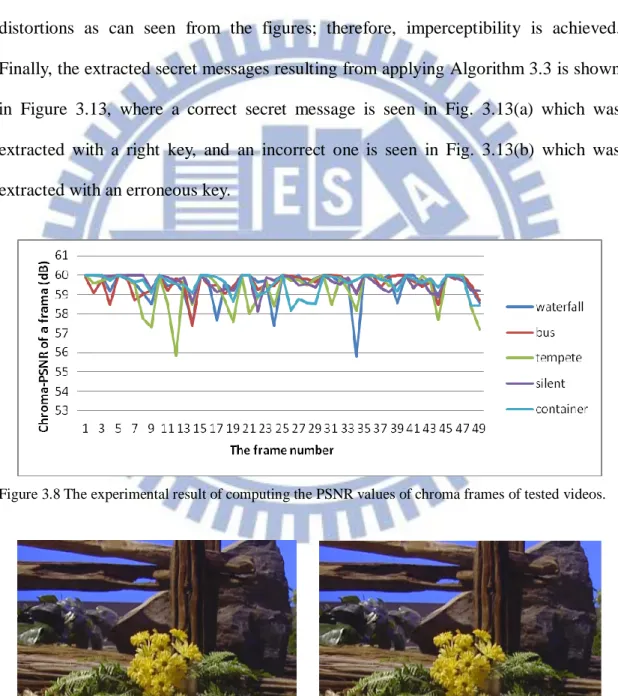
Figure 3.8 The experimental result of computing the PSNR values of chroma frames of tested videos. ... 41
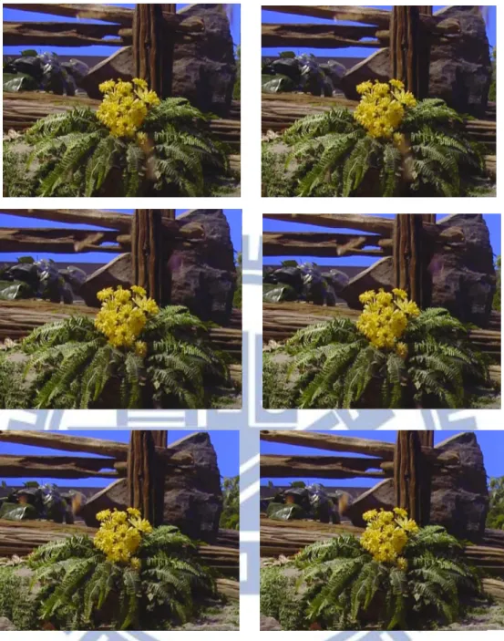
Figure 3.9 The 8th, 9th, 12th, and 49th frames of original video (left) Tempete and stego-video (right)... 42
Figure 3.10 The 24th and 34th frames of original video Waterfall (left) and stego-video (right)... 43
Figure 3.11 The 14thframe of original video Bus (left) and stego-video (right). ... 43
Figure 3.12 The 27thframe of original video Container (left) and stego-video (right). ... 43
Figure 3.13 Extracted secret messages. (a) The correct secret message with a right key. (b) The incorrect secret message with an erroneous key. ... 44
Figure 4.1 An example of different prediction modes in the content of a video. ... 49
Figure 4.2 An example of motion regions. ... 50
Figure 4.3 An example of noise macroblocks. ... 50
Figure 4.4 The notations of the eight neighboring macroblocks of MB. ... 54
Figure 4.5 A flowchart of the process for embedding authentication signals. ... 57
Figure 4.6 A flowchart of the process for authentication signal extraction. ... 61 Figure 4.7 Six frames of the original video of test1. (a) The 152th frame (b) The
ix
153th frame (c) The 154th frame (d) The 155th frame (e) The 156th frame (f) The 157th frame. ... 71 Figure 4.8 Six frames of the protected video of test1. (a) The 152th frame (b) The 153th frame (c) The 154th frame (d) The 155th frame (e) The 156th frame (f) The 157th frame. ... 72 Figure 4.9 Six frames of the tampered video of test1. (a) The 152th frame (b) The 153th frame (c) The 154th frame (d) The 155th frame (e) The 156th frame (f) The 157th frame. ... 73 Figure 4.10 Six frames of the authenticated video of test1. (a) The 152th frame (b) The 153th frame (c) The 154th frame (d) The 155th frame (e) The 156th frame (f) The 157th frame. ... 74 Figure 4.11 Six frames of the protected video of test2. (a) The 48th frame (b) The 49th frame (c) The 50th frame (d) The 51th frame (e) The 52th frame (f) The 53th frame... 75 Figure 4.12 Six frames of the authenticated video of test2. (a) The 48th frame (b) The 49th frame (c) The 50th frame (d) The 51th frame (e) The 52th frame (f) The 53th frame... 76 Figure 4.13 Six frames of the protected video of test3. (a) The 68th frame (b) The 69th frame (c) The 70th frame (d) The 71th frame (e) The 72th frame (f) The 73th frame... 77 Figure 4.14 Six frames of the authenticated video of test3. (a) The 68th frame (b) The 69th frame (c) The 70th frame (d) The 71th frame (e) The 72th frame (f) The 73th frame... 78 Figure 4.15 Six frames of the protected video of test4. (a) The 141th frame (b) The 142th frame (c) The 143th frame (d) The 144th frame (e) The 145th frame (f) The 146th frame. ... 79 Figure 4.16 Six frames of the authenticated video of test4. (a) The 141th frame (b) The 142th frame (c) The 143th frame (d) The 144th frame (e) The 145th frame (f) The 146th frame. ... 80 Figure 5.1 An example of reference error. ... 84 Figure 5.2 An example of modify the frequency coefficients in an intra-coded macroblock to yield intra-coded grey macroblocks. ... 85 Figure 5.3 Comparison between the original image and the image whose Y2 coefficients have been lost. (Left) the original image. (Right) the image whose Y2 coefficients have been lost. ... 88 Figure 5.4 The zig-zag scan order. ... 88 Figure 5.5 Six representative frames of a video. (a) The 41 frame. (b) The 53 frame. (c) The 77 frame. (d) The 99 frame. (e) The 124 frame. (f) The 239
x
frame. ... 96 Figure 5.6 Six representative frames of the protected video of Fig. 5.5. (a) The 41 frame. (b) The 53 frame. (c) The 77 frame. (d) The 99 frame. (e) The 124 frame. (f) The 239 frame. ... 97 Figure 5.7 Six representative frames of a recovered video. (a) The 41 frame. (b) The 53 frame. (c) The 77 frame. (d) The 99 frame. (e) The 124 frame. (f) The 239 frame... 98 Figure 5.8 Six frames of a second video. (a) The 40th frame (b) The41th frame (c) The42th frame (d) The 43th frame (e) The 44th frame (f) The 45th frame. 99 Figure 5.9 Six frames of the protected video of Fig. 5.8. (a) The 40th frame (b) The41th frame (c) The42th frame (d) The 43th frame (e) The 44th frame (f) The 45th frame. ...100 Figure 5.10 Six frames of the recovered video. (a) The 40th frame (b) The 41th frame (c) The42th frame (d) The 43th frame (e) The 44th frame (f) The 45th frame. ...101 Figure 5.11 Six frames of a third video. (a) The 131th frame (b) The 137th frame (c) The 147th frame (d) The 160th fame (e) The 174th frame (f) The 181th frame. ...102 Figure 5.12 Six frames of the protected video of Fig. 5.11. (a) The 131th frame (b) The 137th frame (c) The 147th frame (d) The 160th fame (e) The 174th frame (f) The 181th frame. ...103 Figure 5.13 Six frames of the recovered video. (a) The 131th frame (b) The 137th frame (c) The 147th frame (d) The 160th fame (e) The 174th frame (f) The 181th frame. ...104 Figure 5.14 Six frames of a fourth video. (a) The 195th frame (b) The 209th frame (c) The223th frame (d) The 236th frame (e) The 246th frame (f) The 255th frame. ...105 Figure 5.15 Six frames of the protected video of Fig. 5.14. (a) The 195th frame (b) The 209th frame (c) The 223th frame (d) The 236th frame (e) The 246th frame (f) The 255th frame. ...106 Figure 5.16 Six frames of the recovered video. (a) The 195th frame (b) The 209th frame (c) The 223th frame (d) The 236th frame (e) The 246th frame (f) The 255th frame. ...107 Figure 5.17 Comparison between an original image and the corresponding recovered image. (The 77th frame) The average value of PSNR of the recovered area with respect to between the original protected area is 35.73. (a) The original image. (b) The recovered image. ...108 Figure 5.18 Comparison between an original image and the corresponding recovered
xi
image.(The 43th frame) The average value of PSNR of the recovered area with respect to between the original protected area is 30.372. (a) The original image. (b) The recovered image. ...108 Figure 5.19 Comparison between an original image and the corresponding recovered image.(The 147th frame) The average value of PSNR of the recovered area with respect to between the original protected area is 33.361. (a) The original image. (b) The recovered image. ...108 Figure 5.20 Comparison between an original image and the corresponding recovered image.(The 246th frame) The average value of PSNR between the original protected area and the recovered area is 31.374. (a) The original image. (b) The recovered image. ...109
xii
LIST OF TABLES
Table 3.1 Configuration parameters used in this study. ... 錯誤! 尚未定義書籤。 Table 3.2 Values of NHB, PSNRI, and VSI of several video clips.錯誤! 尚未定義
書籤。
Table 4.1 Experimental results of loss rate of authentication signals of test1 video (total number of frames in test1 video is 270, and total number of authentication signals in test1 video is 87)... 錯誤! 尚未定義書籤。
1
Chapter 1
Introduction
1.1 Motivation
With the advance of the Internet and video compression technologies, uses of digital videos nowadays have become part of the human life. WebM is one of the video coding standards developed in recent years, which contains many merits, such as its openness offered by Google Inc., optimality for uses on the web, etc. Specifically, it is well known that the success of the web technology comes mainly from some core techniques such as HTML, HTTP, and TCP/IP whose formats were designed to be open for people to implement and improve. Similarly, as the video is a core to the web experience, WebM was also designed to be 100% free and open-sourced. Also, the WebM format is defined to optimal for the web, in the sense of enabling convenient playbacks on any device, including low-power netbooks, handhelds, tablets, etc. Because of the efficiency and good quality of the WebM video, some popular video sharing web sites, like YouTube, have already used WebM videos widely for user communications. So, WebM is considered very suitable for use as a kind of carrier for information hiding and is investigated in depth in this study.
From another point of view, data hiding techniques can be used to hide secret
messages into given cover videos, resulting in so-called stego-videos. In this way,
stego-videos instead of secret messages themselves may be transmitted through networks. Except the sender of the stego-image and authorized receivers, other users do not know the existence of the hidden information and so will not try to “dig” the
2
information inside because the secret data hidden in a stego-video are usually invisible. It is desired in this study to develop data hiding methods via WebM videos for covert communication.
Another issue is that nowadays video surveillance via uses of video cameras is
everywhere around our living spaces. In some cities like London, thousands or even
more cameras have been deployed around every corner of the cities. Video fidelity and privacy so arouse serious concerns because surveillance videos may contain suspicious or unlawful actions, malicious users might try to acquire videos in illegal ways and tamper with them for misrepresentation. Consequently, we have to consider the fidelity issue of surveillance videos. In addition, a surveillance camera may monitor both public and private spaces in the meantime, violating possibly personal privacy by acquiring images of private individuals‟ activities. Therefore, it is necessary to develop effective methods for authenticating and protecting surveillance videos of the WebM type.
As mentioned above, if surveillance videos contain suspicious or unlawful actions, malicious users might try to acquire videos in illegal ways and tamper with them for misrepresentation. So, video authentication is essential in video surveillance applications and has become a main topic for researches. Embedding invisible authentication signals in a video, which results in a protected video, is a good approach to video authentication. If a malicious user tampers with a protected video, the authentication signal hidden in the video can used to detect and display the tampering. How to generate authentication signals and verify protected surveillance videos are also goals of this study.
Besides, privacy protection is a very important issue in video surveillance. Since video surveillance systems exist everywhere in our environment and usually conduct space monitoring for long time periods, it may record information of individuals and
3
so violate protection of personal privacy. Hence, it is necessary in some cases to hide the privacy-violating parts of the surveillance video content to avoid legal disputes and to protect personal privacy from being misused by suspicious people. This is the final goal of this study.
1.2 General Review of Related Works
Although all the above-mentioned goals of this study are related to the technique of information hiding via videos, different methods should be adopted for different applications. For motion detection, many motion detection algorithms such as temporal differencing, background subtraction, etc. used to detect moving objects have been proposed. For video data hiding, techniques like hiding in motion vectors of the video data, modulating the partition size which is a feature of the video format, etc., have been proposed. For video authentication, techniques like watermarking, digital signatures, etc. are widely used. For privacy protection, lots of techniques have been proposed, such as scrambling of image areas which contain sensitive information, using a set of visual abstraction operators such as silhouette and transparency which controlling the disclosure of individuals‟ privacy visual information, etc. In addition, because the proposed data hiding, authentication, and privacy protection techniques are applied to WebM videos, we will also make a review of the WebM standard in Chapter 2.1.3 Overview of Proposed Methods
1.3.1 Terminologies
4
follows.
1. Secret: a secret is a piece of information that is important and should be
preserved properly and not revealed to unauthorized people.
2. Stego-video: a stego-video is one in which some digital message data are
embedded.
3. Motion region: a motion region is an area containing motion objects in an
input video after a motion detection process.
4. Protected video: a protected video is one into which authentication signals
have been embedded.
5. Video authentication: video authentication is a process for verifying the
integrity and fidelity of a protected surveillance video by checking the authentication signals embedded in it.
6. Privacy-protected area: a privacy-protected area is part of the content of a
surveillance video, in which privacy-violating information has been removed to avoid legal disputes and to protect personal privacy from being misused by suspicious people.
7. Recovered privacy-protected area: a recovered privacy-protected area is part of the content of a video which, being removed before due to privacy-violation, is recovered from a privacy-protected area defined above.
1.3.2 Brief Descriptions of Proposed Methods
In this study, we have developed several methods for data hiding and its applications via WebM videos. They are briefly described in the following.
(A) A data hiding method for covert communication by modifying frequency coefficients in WebM video data
5
A data hiding method which modifies the frequency coefficients of WebM video data for covert communication is proposed in this study. Because the VP8 video codec always conducts compression transformations at the 4×4 resolution, the proposed method modifies the WebM‟s frequency coefficients of the chroma color channels for data hiding. In addition, the PSNR values are computed and compared with a threshold to optimize these changes for maintaining the video quality. For the secret security issue, we select randomly data hiding positions in images in order to reduce the possibility for a malicious user to figure out the locations where the secret data are embedded.
(B) A method for authentication of surveillance videos by analyzing motion objects
A method using the prediction-mode information and motion vectors in the VP8 video codec to detect motion objects and group them into motion regions to generate authentication signals is proposed for video authentication in this study. If a protected video has been tampered with, according to the authentication signals embedded in it, the proposed authentication system can detect and verify this video to indicate how and where the protected video is tampered with.
(C) A method for protection of personal privacy in surveillance videos using WebM video features
A method using an information hiding technique is proposed in this study for removing, hiding, and recovering video contents containing sensitive personal information. A video can be decoded correctly based on some decoding information including motion vectors and frequency coefficients. Therefore, the original decoding information may be removed from the original video stream and set to some predefined values in order to cover video contents with sensitive
6
privacy information and replace them with background image parts. The removed decoding information is not eliminated but embedded into the video and can be extracted later from the privacy protected video in case there is a need of retrieving the privacy-sensitive contents.
1.4 Contributions
New methods for data hiding and applications via WebM videos are proposed in this study. The contributions made in this study are summarized in the following.
1. For the first time, WebM videos are used as carriers for information hiding. 2. New applications of using the region-of-interest map, which is a feature of
the VP8 video codec in the WebM video, are proposed.
3. A data hiding method based on some properties of the VP8 video codec is proposed.
4. A method of motion detection in videos based on the prediction-mode information in the VP8 video codec is proposed.
5. A video authentication system using some features of the VP8 video codec as authentication signals is proposed.
6. A new application of using the golden reference frame in the VP8 video codec to solve the privacy protection problem is proposed.
7. A method for hiding the privacy-sensitive content in a given WebM video and restoring it later is proposed.
1.5 Thesis Organization
7
detection, video data hiding, video authentication, and privacy protection in surveillance videos, as well as the WebM standard is given in Chapter 2. In Chapter 3, the proposed method for data hiding via WebM videos for covert communication is described. In Chapter 4, the proposed video authentication system for surveillance videos is described. In Chapter 5, the proposed method of privacy protection of surveillance videos is presented. Finally, conclusions and some suggestions for future works are given in Chapter 6.
8
Chapter 2
Review of Related Works and
WebM Standard
In this chapter, we give a survey of related works about data hiding, motion detection, video authentication, and privacy protection in videos in Sections 2.1 through 2.4, respectively. Then, we give a review of the standard of the WebM video in Section 2.5.
2.1 Review of Techniques for Data
Hiding via Videos
Lots of data hiding Techniques have been developed for hiding secret data into various media and documents in the past decade. By this way, secret data can be transmitted covertly or kept securely for various applications. Because the capacities of hiding data in videos are usually larger than hiding data in images or documents, many data hiding techniques via videos have been proposed [1-4]. Hu et al. [1] proposed a method for hiding data in H.264/AVC videos based on the use of intra-prediction modes. The basic idea is to modify 44 intra-prediction modes based on a mapping between 4×4 intra-modes and hidden bits. Their method uses only the intra-coded macroblock to hide data. Hussein [2] proposed a method for embedding data in motion vectors based on their associated prediction error. Yang and Bourbakis [3] proposed a method for embedding data in the DCT coefficients by means of vector
9
quantization. Kapotas et al. [4] proposed a method for embedding data into encoded video sequences, in which the hiding technique is used to modulate the partition size to hide the secret data. This method can only be used for embedding information in inter-coded macroblocks.
2.2 Review of Techniques for Motion
Detection
A lot of motion detection techniques have been proposed to detect moving objects in videos [5-9]. The techniques can be classified into two categories. One is for use in the pixel domain [5-6] and the other in the compressed domain [7-9]. Generally speaking, the approaches used in the pixel domain have to fully decode a compressed video bitstream first, but they can be employed for videos coded according to different video coding standards. On the other hand, each of the approaches used in the compressed domain can perform a motion detection process by partially decoding a compressed video bitstream, but they can only be employed in videos coded according to specific standards, such as H.264/AVC or WebM.
Specifically, Haritaoglu et al. [5] proposed a motion detection method based on background subtraction in the pixel domain. They built a statistical model for a background scene that allows them to detect moving objects even when the background scene is not completely stationary. Lipton et al. [6] proposed another approach based on temporal differencing in the pixel domain, which computes pixel-wise differences between consecutive video frames separated by a constant time to find moving objects. Zeng et al. [7] proposed another approach in the compressed domain by employing a block-based Markov random field (MRF) model in a field formed with motion vectors to segment moving objects during a decoding process.
10
Babu et al. [8] proposed an automatic video object segmentation algorithm for the MPEG video. They estimated first the number of independently moving objects in the scene using a block-based affine clustering method. Object segmentation is then accomplished by an expectation maximization (EM) clustering algorithm.Spyridon et al. [9] proposed a method for automatic direct detection of moving objects in the H.264 compressed domain. Different blocks/sub-blocks are combined with their associated motion vectors in order to denote a moving object. Their method works in the compressed domain as the block-sizes and the motion vectors can be found by partially decoding the H.264 bitsream.
2.3 Review of Techniques for Video
Authentication
Video authentication plays an important role in a digital-rights-management system, so many different methods have been proposed to solve the problem [10-12]. Zhang and Ho [10] introduced a video authentication method which makes an accurate usage of tree-structured motion compensation, motion estimation, and Lagrange optimization of the H.264 standard. As mentioned in the paper, authentication information is embedded according to a best-mode decision strategy in the sense that if a video undergoes any spatial and temporal attacks, the scheme can detect the tampering by the sensitive mode change. Pröfrock et al. [11] proposed a method using skipped macroblocks of an H.264 video to embed authentication data. The data are embedded as a fragile, blind, and erasable watermark with low video quality degradations. In contrast with other authentication methods, the embedding process is done after an H.264 compression process, while others are done during the process. The methods mentioned above usually use additional authentication
11
information to authenticate videos. Ait Saadi et al. [12] proposed a method using content based digital signatures from the transform domain as fragile watermarks and then embeds them in motion vectors with the best partition mode in tree-structured motion compensation.
2.4 Review of Techniques for Privacy
Protection in Videos
Privacy protection has become an important issue along with video surveillance systems. Many different approaches have been introduced in recent years [13-16]. Dufaux et al. [13] introduced a method to protect personal privacy by scrambling regions containing personal information. As a consequence, the scene remains visible, but the privacy-sensitive information is not identifiable. Meuel et al. [14] introduced a method to protect faces in surveillance videos. Any visible information of faces in a video is deleted and embedded in the video that allows further reconstruction of the faces if needed. Zhang et al. [15] proposed a method to protect authorized persons, which are not only removed from a surveillance video, but also embedded into the video. Yu et al. [16] proposed another method protecting individuals‟ privacy by controlling the disclosure of individuals‟ private visual information. A set of visual abstraction operators such as silhouette and transparency is applied, which gradually control individuals‟ private visual information.
2.5 Review of WebM Standard
In this study, all the proposed information hiding, video authentication, and privacy protection techniques employ WebM videos as carriers for hiding information.
12
The WebM project, which is a project founded by Google Inc., is aimed to describe the detail for the WebM standard, which can be found at the WebM project website [17]. We give a brief review of the WebM standard in this section. In Section 2.5.1, the structure of the WebM standard will be described. In Sections 2.5.2 and 2.5.3, the encoding and decoding processes in the WebM standard are described, respectively. In Sections 2.5.4, 2.5.5, and 2.5.6, related WebM features are described.
2.5.1 Structure of WebM standard
WebM is an open media file format designed for the web whose openness was offered by Google Inc. in May 2010. Each WebM file consists of video streams compressed with the VP8 video codec and audio streams compressed with the Vorbis audio codec. The WebM file structure is based on the Matroska media container. All of them are royalty-free patent license products, so developers could develop or do researches on them without considering any patent suit issue.
The VP8 video codec works exclusively with an 8-bit YUV 4:2:0 image format, each 8-bit chroma pixel in the two chroma color space (U and V) correspondsto a 2×2 block of 8-bit luma pixels in the luma color space (Y), and the coordinates of the upper left corner of the Y block are exactly twice the coordinates ofthe corresponding chroma pixels. The pixels are simply a large array of bytes stored in rows from top to bottom, each row being stored from left to right. This “left to right” then “top to bottom” raster-scan order is reflected in the layout of the compressed data.
Also, each frame is decomposed into an array of macroblocks. A macroblock is a square array of pixels whose Y dimensions are 16×16 and whose U and V dimensions are 8×8. The macroblock-level data in a compressed frame are also processed in a raster-scan order. The macroblocks are further decomposed into 4×4 subblocks. So
13
every macroblock has sixteen Y subblocks, four U subblocks, and four V subblocks. Like other video codecs, the VP8 video codec also has a transform process which converts pixels in the spatial domain into coefficients in the frequency domain. In the VP8 video codec, the discrete cosine transform (DCT) and the Walsh-Hadamard transform (WHT) always conduct compression at the 4×4 resolution. The DCT is used for the sixteen Y, four U, and four V subblocks. The WHT is used to encode a 4×4 array comprising the average intensities of the sixteen Y subblocks of a macroblock. These average intensities are, up to a constant normalization factor, nothing more than the zeroth DCT coefficients of the Y subblocks. The VP8 video codec considers this 4 ×4 array as a second-order subblock called Y2.
There are two frame types in the VP8 video codec which are intra-frame and
inter-frame. Intra-frames (also called key frames or I-frames) are decoded without
reference to any other frame in a sequence. Key frames provide random access points in a video stream. Inter-frames (also called prediction frames or P-frames) are encoded with reference to prior frames, specifically all prior frames up to and including the most recent key frame. The VP8 video codec uses three types of reference frames for prediction frames: prior frame, golden reference frame, and
alternate reference frame. We will have more illustrations about the golden reference
frame and the alternate reference frame which are features of the VP8 video codec in Section 2.5.5.
2.5.2 Process of Encoding
The process of encoding of WebM videos is illustrated in Figure 2.1. There are two data flow paths, forward and reconstruction. In the forward path, a macroblock is
14
encoded in the intra-mode or inter-mode. In the intra-mode, the encoder calculates the best intra-prediction mode which uses the current encoded blocks as references. In the inter-mode, the encoder calculates the best inter-prediction mode from the last frame or the golden reference frame. After deciding the prediction mode, the encoder generates prediction blocks/buffers. In the intra-mode, the encoder subtracts 128 from each pixel which needs to be encoded. In the inter-mode, the encoder subtracts values of pixels of the current block from those of corresponding pixels of a block which is selected by the motion vector. Both the intra-mode and the inter-mode will produce a residual block.
Also, each 16×16 macroblock is divided into sixteen 4×4 DCT blocks, each of which is transformed by a bit-exact DCT approximation. After the DC coefficients of these bit-exact DCT blocks are collected into another group,all DC coefficients set as zero. Furthermore, this group performs the Walsh-Hadamard transform in order to increase the compression rate. After that, transformed coefficients of these blocks are quantized. Then, each resulting block is scanned in a zig-zag order and entropy encoded. Here, entropy coding is the process of taking all information from all the other processes: DCT coefficients, prediction mode, motion vectors, and so forth and compressing them losslessly into the final output file.
In the reconstruction path, the encoder decodes (reconstructs) each block in a macroblock which is regarded as a reference for further prediction. The quantized coefficients are scaled and inverse-transformed to product a difference block, and then the prediction is added to the difference block to product a reconstructed block. Finally, a loop filter is used to reduce the effects of blocking distortion and the reconstructed reference picture is created from a series of blocks.
15 Original 16x16 Macroblock Sixteen 4x4 Subblock Generate Prediction Block/Buffer Subtract 128 from each pixel Discrete Cosine Transform 4x4 DC-coefficients Quantizer Quantizer Walsh-Hadamard Transform Dequantizer Inverse Walsh-Hadamard Transform
Dequantizer Inverse Discrete Cosine Transorm In-Loop Filter Make all DC-coefficients as zero Entropy Encode Subtract Prediction Buffer from each pixel
+ + In-Loop Filter Reconstruc ted Frame(Fn) Current Frame(Fn) Reference Frame(Fn-1 or last golden frame) Bitstream Choose Prediction Mode
Figure 2.1 Flow diagram of WebM encoding process.
2.5.3 Process of Decoding
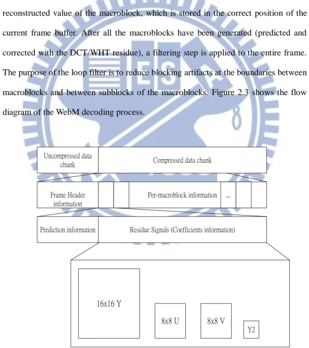
The decoder receives a compressed bitstream. First, the frame header (the beginning of the first data partition) is decoded. Then, the macroblock data occur in raster-scan order. These data come in two more parts. The first part is a prediction mode coming in the remainder of the first data partition. The other part comprises the data partition(s) for the DCT/WHT coefficients of the residue signal. Figure 2.3
16
shows the top-level hierarchy of the WebM video bitstream. For each macroblock, the prediction data must be processed before the residue. Each macroblock is predicted using one (and only one) of four possible frames, namely, the current frame, the immediately previous reconstructed frame, the most recent golden reference frame, and the recent alternate reference frame.
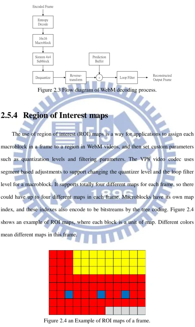
Regardless of the prediction method, the residue DCT signal is decoded, dequantized, reverse-transformed, and added to the prediction buffer to produce the reconstructed value of the macroblock, which is stored in the correct position of the current frame buffer. After all the macroblocks have been generated (predicted and corrected with the DCT/WHT residue), a filtering step is applied to the entire frame. The purpose of the loop filter is to reduce blocking artifacts at the boundaries between macroblocks and between subblocks of the macroblocks. Figure 2.3 shows the flow diagram of the WebM decoding process.
Per-macroblock information
Residue Signals (Coefficients information) Frame Header
information Prediction information
Uncompressed data
chunk Compressed data chunk
...
16x16 Y
8x8 U 8x8 V
Y2
17
Dequantize transform
Reverse-Prediction Buffer Loop Filter 16x16 Macroblock Sixteen 4x4 Subblock
+ Reconstructed Output Frame Encoded Frame
Entropy Decode
Figure 2.3 Flow diagram of WebM decoding process.
2.5.4 Region of Interest maps
The use of region of interest (ROI) maps is a way for applications to assign each macroblock in a frame to a region in WebM videos, and then set custom parameters such as quantization levels and filtering parameters. The VP8 video codec uses segment based adjustments to support changing the quantizer level and the loop filter level for a macroblock. It supports totally four different maps for each frame, so there could have up to four different maps in each frame. Macroblocks have its own map index, and these indexes also encode to be bitstreams by the tree coding. Figure 2.4 shows an example of ROI maps, where each block is a unit of map. Different colors mean different maps in this frame.
18
2.5.5 Reference Frames
The VP8 video codec uses three types of reference frames for inter prediction: the prior frame, a golden reference frame, and an alternate reference frame. Overall, this design has a much smaller memory footprint on both the encoder and the decoder than designs with many more reference frames. More details of the golden reference frame and the alternate reference frame are illustrated below,
(A) Golden Reference Frame
The VP8 video codec was designed to use one reference frame buffer to store a video frame from an arbitrary point in the past. This buffer is known as the golden
reference frame. The VP8 encoder could use the golden reference frame in many ways
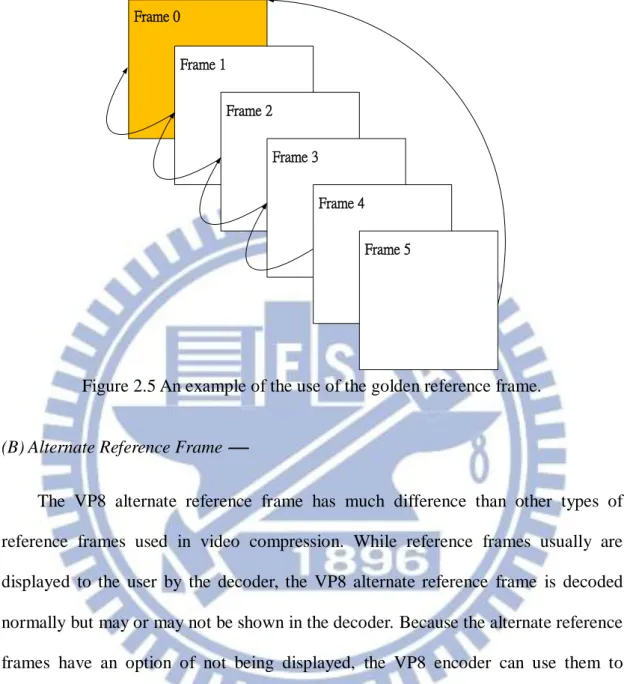
to improve coding efficiency. One situation is that it can be used to maintain a copy of the background image when there are objects moving in the foreground part; by using the golden reference frame, the foreground part can be easily and cheaply reconstructed when a foreground object moves away. Another example is using the golden reference frame to encode back and forth cut of two scenes, where the golden reference frame buffer can be used to maintain a copy of the second scene. Finally, the golden reference frame can also be used for error recovery in a real-time video conference, or even in a multi-party video conference for scalability. Figure 2.5 shows an example of using the golden reference frame. In Figure 2.5, Frame 0 is a key frame and also a golden reference frame. Frame 1 through Frame 4 build a predictor using the prior frame. Frame 5 uses only Frame 0 as a reference. If any frames between Frame 1 to Frame 4 are lost, the VP8 video codec still can decode Frame 7 because it references only to Frame 0.
19 Frame 0 Frame 1 Frame 2 Frame 3 Frame 4 Frame 5
Figure 2.5 An example of the use of the golden reference frame.
(B) Alternate Reference Frame
The VP8 alternate reference frame has much difference than other types of reference frames used in video compression. While reference frames usually are displayed to the user by the decoder, the VP8 alternate reference frame is decoded normally but may or may not be shown in the decoder. Because the alternate reference frames have an option of not being displayed, the VP8 encoder can use them to transmit any data that are helpful to compression. The flexibility in the VP8 specification allows many types of usage of the alternate reference frame for improving coding efficiency. For example, the VP8 video codec has a lack of B frames, which led to discussions in the research community about the ability to achieve high compression efficiency in the VP8 video codec. So, the VP8 video codec intelligently uses the golden reference frame and the alternate reference frames together to compensate for this problem.
20
2.5.6 VP8 Intra Prediction and Inter Prediction
To encode a video frame, a block-based video codec, such as the VP8 video codec, at first decomposes the frame into smaller segments called macroblocks. For each macroblock in the VP8 video codec, the encoder will predict redundant motion and color information based on previously processed macroblocks. The redundant information can be subtracted and transformed from the macroblock, resulting in more efficient compression. The VP8 encoder uses two prediction types: intra
prediction and inter prediction. The intra prediction uses data within an encoded
macroblock in this frame so it does not reference any previously encoded frames; and the inter prediction uses data from previously encoded frames, so the residual signal data areencoded using other techniques, such as transform coding.
(A) VP8 Intra Prediction Modes
The VP8 video codec uses three types of macroblocks in intra prediction modes,
4×4 luma, 16×16 luma, and 8×8 chroma. Five intra prediction modes are shared by
these macroblocks. The first is the H_PRED (horizontal prediction), which fills each column of the block with a copy of the left column. The second is the V_PRED (vertical prediction), which fills each row of the block with a copy of the row above. The third is the DC_PRED (DC prediciton), which fills the block with a single value using the average of the pixels in the row above, A, and the column to the left, L (see Fig. 2.6). The fourth is the B_PRED, which divides a macroblock into sixteen blocks with each block having its own prediction modes. The last is the TM_PRED (TrueMotion prediction), which is a new compression prediction technique developed by On2 Technologies. We illustrate more details about TrueMotion prediction below.
21
In addition to the row A and the column L, TreMotion prediction uses the pixel C above and to the left of the block. Horizontal differences between pixels in A (starting from C) are propagated using the pixels from L to start each row. As mentioned above, the TM_PRED mode is unique to the VP8 video codec. Figure 2.6 uses an example 4× 4 block of pixels to illustrate how the TM_PRED mode works, where C, Ax and Lx (x
= 0, 1, 2, 3) represent reconstructed pixel values from previously encoded blocks, and
X00 through X33 represent predicted values for the current block. The TM_PRED mode
uses the following equation to calculate Xij:
ij i j X L A C (i, j = 0, 1, 2, 3). A0 A1 A2 A3 X00 X01 X02 X10 X11 X12 X03 X13 X22 X21 X23 X20 C L0 L1 L2 X32 X31 X33 X30 L3
Figure 2.6 An example of 4×4 block of pixels.
Although the above example uses a 4×4 block, the TM_PRED mode for 8×8 and 16×16 blocks works in the same way. The TM_PRED prediction mode is one of the more frequently used intra prediction modes in the VP8 video codec. Generally speaking, together with other intra prediction modes, the TM_PRED prediction mode helps the VP8 video codec to achieve very good compression efficiency, especially for key frames, which can only use intra modes.
22
In the VP8 video codec, inter prediction modes are used only on inter frames (non-key frames). For any VP8 inter frame, typically three previously coded reference frames can be used for prediction. A typical prediction block is constructed using a motion vector to copy a block from one of the three frames. The motion vector points to the location of a pixel block to be copied. In most video compression schemes, a good portion of the bits are spent on encoding motion vectors; the portion can be especially large for videos encoded at lower data rates. The VP8 video codec encodes motion vectors very efficiently by reusing motion vectors from neighboring macroblocks. The VP8 video code uses a similar strategy in the overall design of inter prediction modes. For example, the prediction modes "NEARESTMV" and "NEARMV" make use of the last and second-to-last, non-zero motion vectors from neighboring macroblocks. And the prediction mode “ZEROMV” whose motion vectors in this macroblock is zero. These inter prediction modes can be used in combination with any of the three different reference frames.
In addition, the VP8 video codec has a very complicated, flexible inter prediction mode called SPLITMV. It is also a unique new compression prediction technique developed by On2 Technologies. This prediction mode was designed to enable flexible partitioning of a macroblock into sub-blocks to achieve better inter prediction. The SPLITMV prediction mode is very useful when objects within a macroblock have different motion characteristics. Within a macroblock encoded by the SPLITMV prediction mode, each sub-block can have its own motion vector. Similar to the strategy of reusing motion vectors at the macroblock level, a sub-block can also use motion vectors from neighboring sub-blocks above or left to the current block. This strategy is very flexible and can effectively encode any shape of sub-macroblock partitioning, and very efficiently. Figure 2.7 and Figure 2.8 illustrate an example of a macroblock using the SPLITMV prediction mode. In Figure 2.7, NEW represents a 4×4
23
block encoded with a new motion vector, and LEFT and ABOVE represent a 4×4 block encoded using the motion vector from the left and above, respectively. As can be seen from Figure 2.8, macroblocks have three different colors; and each color represents a segment with different motion vectors, so there exist three different motions in these macroblock.
NEW LEFT LEFT NEW
ABOVE LEFT LEFT ABOVE
ABOVE NEW LEFT ABOVE
ABOVE ABOVE LEFT LEFT
Figure 2.7 An example of the SPLITMV prediction mode.
24
Chapter 3
Data Hiding in WebM Videos for
Covert Communication by
Frequency Coefficient Modifications
3.1 Introduction
Due to the growth of computer network and audio/video compression technologies, many applications of digital media have emerged on the network. The preservation and transmission of secret information are interesting research topics. To solve such covert communication problems, the use of data hiding techniques is a good solution. In this way, we can hide secret data into cover media, and the hidden information is desirably imperceptible in general. Videos are suitable for use as cover media for this purpose because more data can be hidden in videos than in images or in other documents. In addition, because of the efficiency and good quality of the WebM video, some popular video sharing web sites, like YouTube, have already used WebM videos widely for user communications. Considering this popularity of the WebM video, we propose a data hiding method via WebM videos for covert communication in this study, which we describe in this chapter.
In Section 3.1.1, some relevant definitions are given, and in Section 3.1.2 the basic ideas of the proposed method are presented. In Section 3.2, the proposed data hiding method is described in detail, and the corresponding data extraction method is presented in Section 3.3. In Section 3.4, some experimental results are shown to prove
25
the feasibility of the proposed method. Finally, discussions and a summary of the proposed method are made in the last section of this chapter.
3.1.1 Problem Definition
When data hiding techniques via videos are applied for covert communication, the amount and imperceptibility of the hidden data are two major concerns. Furthermore, with the popularity of web applications, people give more and more attention to low bit rate videos. Therefore, an additional problem is how to hide data into videos in an optimal way to reduce the increase on the bit rate of the stego-video. Finally, the enhancement of the hidden secret security should also be taken into considerations.
3.1.2 Proposed Ideas
In the method proposed in this study for hiding data via WebM videos for covert communication, because the transform coding scheme in the VP8 video codec always conducts compression at the 4×4 resolution, we try to modify the WebM‟s frequency coefficients of the chroma color space in the compression result and generate data patterns for data hiding. In addition, the PSNR values are computed and compared with a threshold to optimize these changes for maintaining the video quality and the bit rate. For secret security enhancement, first we calculate the total number of macroblocks which can be used to embed data and the total size of the secret message. Then, we use a key together with a random number generator to select randomly data hiding positions in images, preventing a malicious user from figuring out the locations where the secret data are embedded.
There are two frame types in WebM videos, namely, key frame (I frame) and
26
utilizes the prediction frame.
3.2 Embedding of Secret Data into
WebM Videos
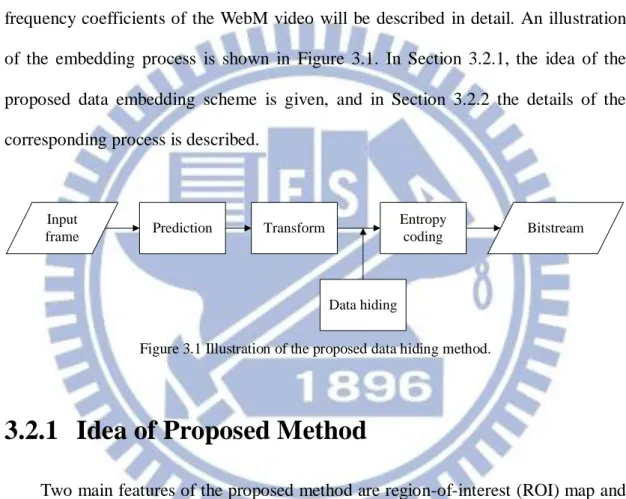
In this section, the proposed method for embedding secret data into the frequency coefficients of the WebM video will be described in detail. An illustration of the embedding process is shown in Figure 3.1. In Section 3.2.1, the idea of the proposed data embedding scheme is given, and in Section 3.2.2 the details of the corresponding process is described.
Input
frame Prediction Transform
Entropy
coding Bitstream
Data hiding
Figure 3.1 Illustration of the proposed data hiding method.
3.2.1 Idea of Proposed Method
Two main features of the proposed method are region-of-interest (ROI) map and frequency-coefficient pattern, whose functions for use in this study are described first below.
(A) Region-of-Interest Map
As mentioned in Section 2.5.4, the VP8 video codec supports up to four maps for each frame. Each macroblock has its own map index, and such an index is also encoded into the bitstream by tree coding. Here, we propose a scheme for assigning a map index for use as a data extraction mark to label macroblocks whose coefficients
27
are modified for embedding secret information. As a result, the proposed scheme can be used to indicate the macroblock positions in images where the secret information exists.
(B) Frequency Coefficient Patterns
As mentioned in Section 2.5.1, the macroblock-level data in a compressed frame in a WebM video is processed in a raster-scan order, and the macroblock is a square array of pixels whose Y components are 16×16 and U and V components are 8×8. Each macroblock is decomposed further into 4×4 subblocks, so that every macroblock has sixteen Y subblocks, four U subblocks, and four V subblocks. Figure 3.2 shows one of the subblocks, whose size is 4×4. The DCT (discrete cosine transform) and WHT (Walsh-Hadamard transform) are always performed to conduct compression at the 4×4 resolution in the VP8 video codec. And the pixel values in a subblock, after the DCT is conducted, will be transformed into frequency-domain coefficients, and the energy of the coefficient signals is “clumped” at the left-upper corner of the subblock.
In addition, after the quantization step with an adaptive quantization level is conducted, non-zero or zero coefficients will appear in the middle area of a quantized subblock. At this area of non-zero and zero coefficients, pre-defined data patterns may be generated automatically to replace them for imperceptible data hiding. Figure 3.3 shows an example of a subblock after performing the DCT and quantization. Furthermore, by the research results of the color theory [18], we know that human eyes have lower sensitivity on high-frequency signals and chrominance than on low-frequency signals and luminance.
According to the above discussions, we propose a data hiding scheme based on the DCT at the 4×4 resolution in this study, which modifies up to four coefficients on
28
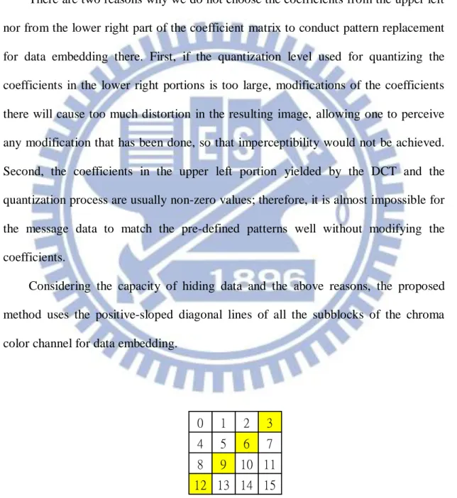
the “positive-sloped diagonal line” of the 44 subblock of the quantized frequency coefficients using sixteen pre-defined 44 patterns to represent the message information to be embedded. Here, by the positive-sloped diagonal line, we mean those yellow-colored squares in the 44 coefficient matrix (corresponding to a subblock) shown in Fig. 3.2 or those red-colored ones shown in Fig. 3.3.
There are two reasons why we do not choose the coefficients from the upper left nor from the lower right part of the coefficient matrix to conduct pattern replacement for data embedding there. First, if the quantization level used for quantizing the coefficients in the lower right portions is too large, modifications of the coefficients there will cause too much distortion in the resulting image, allowing one to perceive any modification that has been done, so that imperceptibility would not be achieved. Second, the coefficients in the upper left portion yielded by the DCT and the quantization process are usually non-zero values; therefore, it is almost impossible for the message data to match the pre-defined patterns well without modifying the coefficients.
Considering the capacity of hiding data and the above reasons, the proposed method uses the positive-sloped diagonal lines of all the subblocks of the chroma color channel for data embedding.
0 1 2 3 4 5 6 7 8 9 10 11 12 13 14 15
Figure 3.2 An example of subblocks with yellow coefficients composing a positive-sloped diagonal line.
29
81 20 6 -2 11 4 0 0
1 0 0 0 0 0 0 0
Figure 3.3 An example of a subblock after performed DCT and quantization with red coefficients composing a positive-sloped diagonal line.
3.2.2 Process for Embedding Secret Data
In this section, we will describe the detailed algorithm of the proposed method for hiding secret message data into cover videos by changing the frequency coefficients into pre-defined patterns. A flowchart of the proposed data embedding process is shown in Figure 3.5.
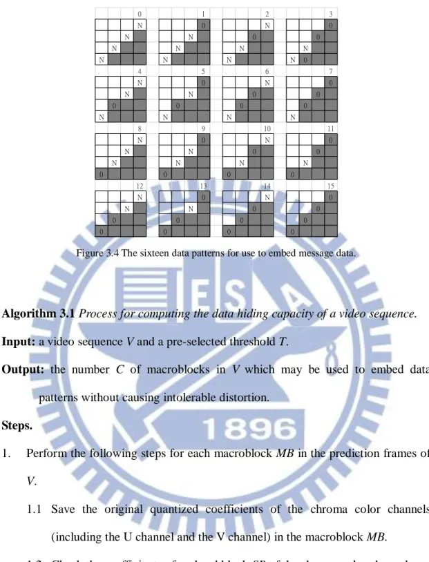
Beforehand, we define in the following the aforementioned 16 data patterns for use in the proposed algorithms where we use the notations N and 0 to denote the meanings “non-zero” and “zero,” respectively.
Data pattern i (i = 0 to 15): a 44 block with its positive-sloped diagonal line being filled with four symbols S4S3S2S1 of N‟s and 0‟s, which correspond to the
binary value b4b3b2b1of i in the following way:
if bj = 0, then Sj = N; otherwise, Sj = 0, j = 1, 2, 3, 4.
Figure 3.4 illustrates the 16 data patterns. For example, when i = 3, the corresponding binary value is i = 310 = 00112, so we define pattern 3 as the 44 block with its
positive-sloped diagonal line being filled with the four symbols S4S3S2S1 = 00NN.
And when i =10, the corresponding binary value is i = 1010 = 10102, so we define
pattern 10 as the 44 block with its positive-sloped diagonal line being filled with
30 0 1 2 3 N 0 N 0 N N 0 0 N N N N N N N N 0 4 5 6 7 N 0 N 0 N N 0 0 0 0 0 0 N N N N 8 9 10 11 N 0 N 0 N N 0 0 N N N N 0 0 0 0 12 13 14 15 N 0 N 0 N N 0 0 0 0 0 0 0 0 0 0
Figure 3.4 The sixteen data patterns for use to embed message data.
Algorithm 3.1 Process for computing the data hiding capacity of a video sequence. Input: a video sequence V and a pre-selected threshold T.
Output: the number C of macroblocks in V which may be used to embed data patterns without causing intolerable distortion.
Steps.
1. Perform the following steps for each macroblock MB in the prediction frames of
V.
1.1 Save the original quantized coefficients of the chroma color channels (including the U channel and the V channel) in the macroblock MB.
1.2 Check the coefficients of each subblock SB of the chroma color channels: if the original coefficientsof SB do not satisfy data pattern 0, then modify
them to be so by changing 0 in them to be 1; else, do nothing.
1.3 (Computing the resulting distortion) Calculate the mean square quantization error (MSQE) between the saved content MBo of the original macroblock
31
MB and the content MBo' of the modified macroblock MB' of the chroma
color channels: 2 o o ( ) i MSQE MBMB (3.1) where i =1 and 2 represent the U channel and the V channel, respectively, and each of MBo and MBo' means an 88 vector of coefficients.
1.4 Calculate the following value of the peak signal-to-noise ratio (PSNR)
PSNRi ofthe chroma color channels for i = 1 and 2:
2 10 log peak i i S PSNR MSQE (3.2)
where Speak meansthe maximum possible pixel value of the image.
1.5 Calculate the average PSNR value PSNRavg of the chroma color channels:
2 1 2 i i avg PSNR PSNR
. (3.3)1.6 (Checking the data embeddability of the macroblock) Use the ROI map index to label the modified macroblock MB' in the following way:
if PSNRavg is smaller than the pre-selected threshold T, then set the the
ROI map index value to be 1, meaning that macroblock MB is
data-embeddable;
else, use the default value of the ROI map index which is 0, meaning that macroblock MB is non-data-embeddable.
2. Increment the value C by one if the ROI map index is set to be 1. 3. Repeat Steps 1 and 2 until all macroblocks are processed.
In Step 2 above, if the ROI map index is set to be 1, it means that this macroblock can be used to embed data without causing intolerable distortion in the resulting macroblock. Also, the number C is used to specify the data hiding capacity
32
of this video sequence in unit of macroblock. In addition, the Parseval theorem [19] states that mean square error (MSE) in the pixel domain is equivalent to the mean square quantization error (MSQE) in the DCT domain because the DCT is a normalized orthogonal transformation. So in Steps 1.3 and 1.4 above, we may also use the original PSNR definition described by Eq. (3.3) below to calculate the PSNR values: 2 10 log Speak PSNR MSE . (3.4)
where Speak meansthe maximum possible pixel value of the image.
With the data embedding capacity C computed, we can now describe the proposed method for data embedding as an algorithm in the following.
Algorithm 3.2 Process for embedding secret data into a WebM video.
Input: a video V, a secret key K, a random number generator f, and a secret message S.
Output: a stego-video V’. Steps.
Stage 1 --- initialization.
1. Process V to compute the data hiding capacity C in V by performing Algorithm 3.1.
2. (Randomizing the secret message) Transform the secret message S into a binary string B, use the secret key K as a seed to generate a sequence Q of random numbers using the random number generator f, and randomize B with Q to get a randomized binary string B'.
33 by: . 32 the length of B' N (3.5)
4. Use the secret key K and the random number generator f to generate a sequence
RS of N random integer numbers with C as the maximum number in the
sequence, and sort them into an ascending order. 5. Divide B' into a linear array A of 4-bit segments.
Stage 2 --- embedding message data into the video.
6. Perform the following steps to embed message S into each unprocessed macroblock MB in every prediction frame of V, assuming V is large enough to embed the entire message.
6.1 Save the original quantized coefficients of the chroma color channels in
MB.
6.2 Check the coefficients of each subblock SB of the chroma color channels: if the original coefficientsof SB do not satisfy data pattern 0, then modify
them to be so by changing 0 in them to be 1; else, do nothing.
6.3 Calculate the mean square quantization error (MSQE) between the saved content MBo of the original macroblock MB and the content MBo' of the
modified macroblock MB' of the chroma color channels:
2 o o
( )
i
MSQE MBMB (3.6) where i =1 and 2 represent the U channel and the V channel, respectively, and each of MBo and MBo' means an 88 vector of coefficients.
6.4 Calculate the value of the peak signal-to-noise ratio (PSNR) PSNRi of the