Embedded Fault-Tolerance Routing and Wavelength Assignment Algorithms in DWDM Networks
18
0
0
全文
(2) Index Terms: DWDM, RWA, QoS, Wavelength conversion, Fault tolerance.. 1. Introduction Wavelength Division Multiplexing (WDM) wavelength routed in all-optical WAN’s have emerged as the most efficient means to meet the ever increasing integrated demands of the communication applications. They have potential to meet the exponential growth in the user traffic catering to the needs of divergent requirements such as high bandwidth online medical applications, real-time rocket and satellite communications, secure transaction processing in federated databases, defense applications, multimedia traffic, supercomputer interconnects along with smaller bandwidth requirements of voice, data and many other applications to millions of users. The inability of the end users to generate data more than a few gigabit/ps (electronic bottleneck) and the huge bandwidth of the fiber has led to the development of WDM technology. The optical transmission bandwidth is split into a number of distinct non-interfering and nonoverlapping wavelength communication channels, which can operate on different optical wavelengths and at different bit rates. The co-existence of a number of channels on a single fiber increases the utilization of the fiber bandwidth throwing challenges to design and development of suitable network.
(3) architectures, protocols and algorithms [1].. C. ATM A. Optical NETWORK. λ. 1. λ2. WDM Router with wavelength converters. λ. λ. λ2. 1. 1. D. λ2. λ2 ATM B Access Node (electronic processing). E. Figure 1 All-optical wavelength-routed network. In all-optical wavelength-routed networks architecture [2], shown in Figure 1, there are many wavelength-routing switches or so called routing nodes [3]. When the data is transmitted from node A to the node B, the device of wavelength converter is applied if the transmission path is changed fromλ2 to λ1. The procedure of the wavelength conversion is to free the wavelength continuity constraint in the all-optical networks, because the light propagates in the straight rather than in the curve. The wavelength is converted under appropriate physical device. The wavelength conversion can efficiently improve the problem of wavelength conflict, and also can increase the wavelength reusable rate. To design a wavelength converter, the response time of the.
(4) wavelength converter will affect the QoS of the networks. Then, the minimum number of converters needed is demanded that the system should assign the converted wavelength from the source to the destination. Such issue related in the field of the wavelength routing and assignment is called Routing and Wavelength Assignment (RWA) issue that is explored in this paper. Yoo [4] proposes that the WDM networks depend on the wavelength routing to utilize the bandwidth of the fiber efficiently and to support a flexible interconnected networks. In the high capacity and dynamic WDM networks, the networks will be blocked if the channels of wavelength are in use. Therefore, the networks apply the wavelength converter to reduce the probability of the blocking. This problem also becomes the key issue of the transmission transparency in the WDM networks [5]. In this paper, we propose the embedded fault-tolerance routing and wavelength assignment algorithm in DWDM networks. There are four phases in the proposed algorithm, which are validation, transformation, allocation (wavelength assignment), and fault tolerant phases, respectively. Particular, a limited bandwidth of dynamic routing and wavelength assignment algorithm, designed in phase 3, called Limited Routing and Wavelength Assignment (LRWA) to solve RWA problems and study the performance of wavelength converters for Static Lightpath Establishment (SLE).
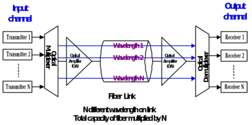
(5) and Dynamic Lightpath Establishment (DLE), respectively [6]. The rest of this paper is organized as follows. Section 2 examines the network model. Section 3 describes the system model and four-phased algorithm. Section 4 evaluates and compares the simulation results. Concluding comments and future works are given in Section 5.. 2. Network model The network model consists of a number of access stations attached to a group of wavelength routing nodes. Each access station has at least one tunable optical transmitter and one tunable optical receiver as well as optoelectronic interface to the user(s). The physical topology of the WDM optical networks consists of wavelength routing nodes, interconnected by pairs of point-to-point fiber links an arbitrary topology, which is shown in Figure 2.. Output channel. Input channel Transmitter 1 Optical Ampilifer (OA). Wavelength 2. Optical Ampilifer (OA). Wavelength N Transmitter N. Optical De-multiplexer. Optical Multiplexer. Transmitter 2. Receiver 1 Wavelength 1 Receiver 2. Receiver N. Fiber Link N different wavelength on link Total capacity of fiber multiplied by N. Figure 2 Architecture of DWDM system.
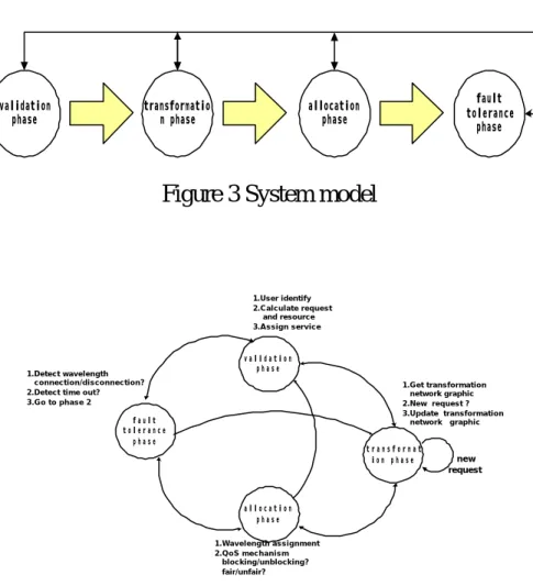
(6) Wavelengths are assigned to the transmitters and receivers to create several independent channels, which are multiplexed onto the optical fiber defining the logical connectivity among the nodes. In this architecture, the function of wavelength multiplexers provides the advantage of higher aggregate system.. 3. Algorithm Description. validation phase. transformatio n phase. fault tolerance phase. allocation phase. Figure 3 System model. 1.User identify 2.Calculate request and resource 3.Assign service. 1.Detect wavelength connection/disconnection? 2.Detect time out? 3.Go to phase 2. validation phase 1.Get transformation network graphic 2.New request ? 3.Update transformation network graphic. fault tolerance phase. transformat ion phase. allocation phase 1.Wavelength assignment 2.QoS mechanism blocking/unblocking? fair/unfair?. Figure 4 System state diagram. new request.
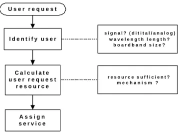
(7) In this paper, we design a four-phased system model, which is shown in Figure 3. The system state diagram is shown in Figure 4. The system model includes four-phased mechanism such as validation, transformation, allocation (wavelength assignment), and fault tolerance. The function of each phase is explained in detail in the following.. User request. Identify user. signal? (ditital/analog) wavelength length? boardband size?. Calculate user request resource. resource sufficient? mechanism ?. Assign service. Figure 5.1 the flow chart of validation algorithm in the phase 1. In the first phase (the validation phase), the main responsibility is to identify the users and to assign the service [8][9]. User identification deals with the various user information to establish the connection between source and destination. That information includes analog or digital signals, the length of the wavelength, bandwidth, etc. According to the request of the users, the algorithm.
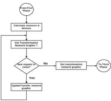
(8) moderately distributes resource to the users. The resource requested by each user should be reckoned in this phase. The flow chart of validation algorithm in the first phase is shown in Figure 5.1.. From First Phase. Calculate resource & devices. Get Transformation Network Graphic ?. New request in come?. No. Get transfomation network graphic. To Third Phase. Yes UpdateTransfer network graphic. Figure 5.2 the flow chart of the transformation algorithm in the phase 2. In the second phase (transformation phase), the major works are the reckoning and repartition of the devices, transformation of the networks graph, and updating the transfer network graph. The reckoning and repartition of the devices are to calculate the amount of the devices, which are capable to support the service and to transform the devices and service into networks graph. If there is a new request, then the new network graph should be renewed. After these three functions have been done in the second phase, it means the.
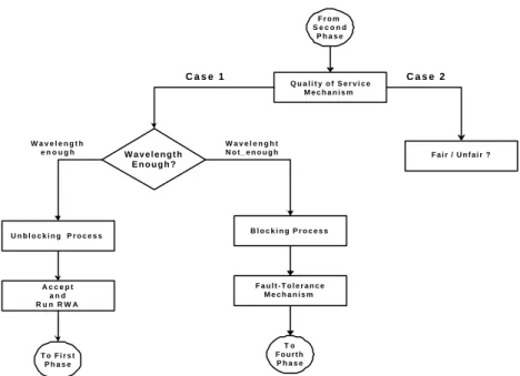
(9) transmission path has been established from the source to the destination. Otherwise, it means the transmission path connection is failure, and then the system will be refused to transmit the data. The flow chart of transformation algorithm in the second phase is shown in Figure 5.2.. From Second Phase. Case 1. Wavelength enough. Unblocking Process. Accept and Run RWA. To First Phase. Wavelength Enough?. Quality of Service Mechanism. Wavelenght Not_enough. Case 2. Fair / Unfair ?. Blocking Process. Fault-Tolerance Mechanism. To Fourth Phase. Figure 5.3 the flow chart of LRWA algorithm in phase 3. In the third phase (allocation phase), the main responsibility is to apply the proposed algorithm of Limited Routing and Wavelength Assignment (LRWA) to repartition the system resources. There are some causes to reject the connection in this phase. For example, the inefficiency of the wavelength, unjustly use the resource causing the low QoS and blocking, will make the rejection in the connection. This algorithm provides the function of refusing.
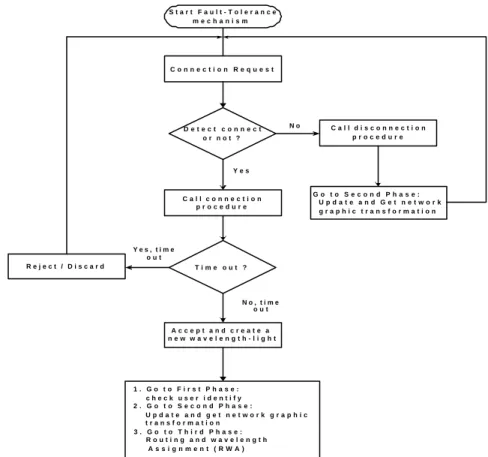
(10) detection in the connection when QoS of the system is too low. This feature could reduce probability of the network blocking in each connection. The flow chart of the LRWA algorithm in phase 3 is shown in Figure5.3.. Start Fault-Tolerance mechanism. Connection Request. Detect connect or not ?. No. Call disconnection procedure. Yes. Call connection procedure. Go to Second Phase: Update and Get network graphic transformation. Yes, time out Reject / Discard. Time out ?. No, time out Accept and create a new wavelength-light. 1. Go to First Phase: check user identify 2. Go to Second Phase: Update and get network graphic transformation 3. Go to Third Phase: Routing and wavelength Assignment (RWA). Figure 5.4 fault tolerance algorithm in phase 4. In the fourth phase (fault tolerance phase), the main job is to support a fault tolerance mechanism when the connection is rejected by the system. The fault tolerance mechanism can make a decision of keeping connection or not. If the system decides to keep connection, the network graph should be update on time. Otherwise, the connection should be aborted. The algorithm is shown in.
(11) Figure 5.4 When the connection is established, the first step is to test if the connection is successful or not. If the connection is successful, then the system will call the connection successful procedure and then execute the fault tolerance mechanism until time out. If the connection is unsuccessful, then the system will call the connection unsuccessful procedure and become a new request to execute request-applying procedure. The network graph should be updated and the fault tolerance decision mechanism should be executed.. 4. Numerical results Simulations are carried out to evaluate the impact of wavelength converters on the blocking probability for SLE and DLE in the 28-node U.S long haul network and 20-node arbitrary mesh network [6][7]. The connection requests are uniformly distributed over all access station pairs.. 24 1. 7. 6. 12 8. 25. 2 5. 28. 27. 13. 9. 26 23. 10. 17. 3 14. 11. 22 18. 4. 21 16 20. 15. 19. Figure 6 the 28-node U.S long haul network.
(12) Figure 6 shows the placement of wavelength converters at nodes with high nodal degree i.e., at 5, 9, 10, 11, 13, 16, 17, 18, 27 and 28 in the 28-node network. These nodes transit a large number of paths and hence require wavelength converters. Four different situations are considered to study the effects of the wavelength converters (WC) on the blocking probability (i) No convertibility at any node (NO_WC). (ii) Full convertibility at all nodes (Full_WC). (iii) Full convertibility at nodes with low nodal degree (LN_WC).. Wavelength converter blocking probability. (iv) Full convertibility at nodes with high nodal degree (HN_WC).. 0.4 0.35 0.3 0.25 0.2 0.15 0.1 0.05 0. No_WC Full_WC HN_WC LN_WC. 50. 100. 150. 200. 250. 300. 350. Number of Lightpaths. Figure 7 Comparison of WC probabilities for four parameters in different channels. In the Figure 7, [6] we compare the blocking probability of WC for four.
(13) different situations in different channels. The results show that the blocking rate is high if the nodes in the networks without WC. However, the results can be reversed if we compare the arrival rate probability for four different situations, which are shown in Figure 8.. Arrival rate probability. 0.6 0.5 No_WC. 0.4. Full_WC. 0.3. HN_WC LN_WC. 0.2 0.1 0 50. 100. 150. 200. 250. 300. 350. Number of Lightpaths. Figure 8 Comparison of demand of arrival rate probabilities for four situations in different channels. It is the fastest to reach the demand of the arrival rate, but the blocking rate is the highest if the nodes in the networks without WC. By contrast, if WC is installed on each node, it will be the slowest to reach the demand of arrival rate; nevertheless, the blocking rate is the lowest. It is obviously that we can distinguish the probability of wavelength reusable rate in the different lightpaths, which is shown in Figure 9. Due to the proposed mechanism with the fault.
(14) tolerance, the node will wait for the release of the channel in the reasonable duration when the resource of the lightpaths is inefficient. This novel feature is. wavelength reusable rate probability. helpful to avoid theλbeing discarded.. 0.8 0.7 0.6 0.5 0.4 0.3 0.2 0.1 0. LRWA DLE. 50. 100. 150. 200. 250. 300. 350. Number of Lightpaths. Figure 9 the probability of wavelength reusable rate from LRWA algorithm and DLE algorithm in different lightpaths. Wavelenght converter probability. 0.5 0.4 0.3. LRWA. 0.2. DLE. 0.1 0 50. 100. 150. 200. 250. 300. 350. Number of Lightpaths. Figure 10 the probability of wavelength converter from LRWA algorithm and DLE algorithm in different lightpaths.
(15) The algorithm of DLE, which is proposed in [6], does not consider the fault tolerance, so the probability of wavelength reusable rate for the lightpath is low. However, it increases the probability of wavelength converter for embedded with fault tolerance, which is shown in Figure 10. When full convertibility is introduced at all nodes, the number of wavelength converters is equal to the product of degree of the node and wavelengths per fiber link, then the network behaves like a classical circuit switched network. It is observed that full convertibility at all nodes gives the lowest blocking probability, while, using no wavelength conversion at any node and full conversions at nodes with low nodal degree give almost the same performance. The best option is to place the wavelength converters at the most congested nodes or nodes with high nodal degree. These nodes are marked in the network. It gives a good trade-off between the cost and the overall blocking probability of the network. The blocking probability increases with the increase in the number of static lightpath set and finally stabilizes after a certain number of lightpath set. The blocking probability reduces with the increase in the number of wavelengths.. 5. Conclusion.
(16) Wavelength converters play an important role in circuit switched optical networks. Wavelength convertible networks reduce blocking probability, increase wavelength reuse, reduce congestion, support higher loads, ensure easier rerouting thereby increasing throughput of the network. Four-phased system model is proposed, which includes validation phase, transformation phase, wavelength assignment phase, and fault tolerance phase. Simulations are carried out to evaluate the impact of wavelength converters on the blocking probability for SLE and DLE. The simulations show that the probability of the blocking is the lowest when all the nodes connect with the wavelength converters. When all the nodes do not have the wavelength converter, the probability of the blocking is the highest. By contrast, when we observe in the wavelength user’s demands of the arrival rate, the wavelength converting will increase the propagation delay. If there are no wavelength converters, the propagation delay will be the lowest. In comparison with the algorithms of proposed fault tolerance mechanism and DLE, we find that LRWA has lower blocking probability and higher lightpath utilization. Due to the feature of the fault tolerance, it is efficient to the wavelength transfer; furthermore, it can increase the utilization rate of the lightpath and reduce the probability of the blocking. In the all-optical networks environment, the congestion will be.
(17) avoided and the QoS will be improved if the wavelength converter is installed in the system. A limited number of wavelength converters placed at nodes having high nodal degree perform equivalent to those networks where all nodes are provided with wavelength converters. Due to the feature of the wavelength continuity in light beam, our goal is to reduce the number of wavelength converters from the system but also keeps its own efficiency. Moreover, the potential for further research for deeper issues will be significant, i.e. developing the algorithm of artificial intelligent routing and wavelength assignment.. 6.. References. [1] A. Birtnan, “Computing approximate blocking probabilities for a class of all-optical networks”, IEEE J Select. Areas Commun., vol. 14., Page(s): 852-857, June 1996. [2] R.A. Barry and P.A. Humblet, “Models of blocking probability in all-optical networks with and without wavelength changers,” IEEE JSAC, vol. 14, No. 5, pp. 858-867, June 1996. [3] B. Ramamurthy and B. Mukherjee, “Wavelength Conversion in WDM Networking”, IEEE Journal on Selected Area in Comm., vol. 16, No. 7,.
(18) Page(s): 1061-1073. September 1998. [4] S.J.B. Yoo, “Wavelength Conversion Technologies for WDM Network Applications”, Journal of lightwave technology, vol.14, No. 6, June 1996. Page(s): 995-996. [5] K.C. Lee and V.O.K. Li. “A wavelength-Convertible Optical Network.” IEEE Journal of Lightwave Technology, 11(5/6): 962-970, May/June 1993. [6] K.R. Venugopal, E.Ezhil Rajan and P.S. Kumar, “Performance analysis of Wavelength converters in WDM Wavelength routed Optical Networks”, IEEE HIPC '98, 5th International Conference, pp. 239-246, 1998. [7] Tibor Fabry-Asztalos, Nilesh Bhide and krishna M. Sivalingam, “Adaptive Weight. Functions. for. Shortest. Path. Routing. Algorithms. for. Multi-Wavelength Optical WDM Networks”, Comm, 2000. ICC 2000. 2000 IEEE International Conference, Vol. 3, Page(s): 1330-1334. [8] A. Jukan and H.R. van as, “Quality-of-service routing in optical networks,” Integrated Optics and Optical Fibre Communications, 11th International Conference on, vol. 3, Page(s): 160-163. 1997. [9] A. Jukan and H.R. van as, “Quality-of-service routing in optical networks,” in Proc. IEEE Int.Conf. Commun., ICC’99, vol. 3, Vancouver, Canada, June 1999, Page(s): 2048-2054..
(19)
數據

+7


相關文件
circuit sat: Given a circuit, is there a truth assignment such that the circuit outputs truea. • circuit sat ∈ NP: Guess a truth assignment and then evaluate
• Each row corresponds to one truth assignment of the n variables and records the truth value of φ under that truth assignment. • A truth table can be used to prove if two
Simulation conditions are introduced first and various characteristics in three defect designs, such as single mode laser wavelength shift and laser mode change, are analyzed.
– Equivalently, there is a truth assignment such that each clause has a literal assigned true and a literal assigned false.. – Equivalently, there is a satisfying truth assignment
◦ Value function: how good is each state and/or action1. ◦ Model: agent’s representation of
The simulation environment we considered is a wireless network such as Fig.4. There are 37 BSSs in our simulation system, and there are 10 STAs in each BSS. In each connection,
In this thesis, we develop a multiple-level fault injection tool and verification flow in SystemC design platform.. The user can set the parameters of the fault injection
Numerical results show that by introducing the binary holes to each unit cell in the PCF, a higher modal birefringence of the order of has been achieved within the wavelength
