18th Annual International Conference of the IEEE Engineering in Medicine and Biology Society, Amsterdam 1996 VTCP7: VideoComputerPoster
The Registration amd Presentation of MR and PET Fusion Imaging
San-Chau Hwang, ',Jyh-Horng Chen, 23Jason J.S. Lee, and 3Shin-HwaYehl.
1.Department
of
Electrical Engineering, Natioln'al Taiwan University
2.
Division
o fRaldio'logical Sciences National Yang-Miing University
3.
National Positron Emission Tomography and Cyclotron Center
1
Taipei, Taiwan
Abstract
We have developed a method that allow us to register 3D multi-modalities imaging sets automatically. This method use the N-bar landmarks(Fig. 1) to register MR and PET imaging. A WINDOWS-95 based software for the presentation of MR and PET fusion imaging has been designed. With friendly operation, this software can interactively display the registered imaging at an arbitrary slice in real time.
Fig. 1 The N-bar landmarks
lntroduction
Clinical diagnosis is often supported by several imaging modalities. For examples, the anatomic and functional information can be individually obtained by MRI and PET (positron emission tomography). The combination of different image intrinsic characteristic from different imaging system can improve the ability of accurale lesion region determination and localization.
We have developed a method that allow us to register 3D multi-modalities imaging sets automaticalty. This method use the N-bar landmarks to solve the transformation paramcters from one imaging coordination to a common physical
coordination. Using these parameters, the work of 3D imaging registration can be achieved by coordinations transformations with a simple matrix operations.
In order to analyze the fused 3D imaging sets, we have developed a Q?INDOWS-95 based software for routine clinical diagnosis. With friendly operation, this software can interactively display the registered imaging at an arbitrary slice in real time.
Methods
Imaging Registration The imaging registration is achieved with two extemal N-bar landmarks which is fixed beside patient's head durinj: scanning. The N-bar landmarks are constructed .by tubes that is filled with cooper s u l f a t e w ) or '*F-cleoxyl glucose(PET). The transformation parameters from one imaging coordination to a common physical coordination, w@ch are defmed to match different imaging sy,stem, include scaling, translation and rotation on each axis. The scaling parameters can be obtained from scanning conditions such as FOV, slice thickness. For solving the: other parameters, a computer program has been developed. This program includes three procedures: Firstly, it identities the positions of external fiducial N-shape landmarks on each image slice. Secondly, it fits these landmark locations onto four vertical lines and one oblique pllane with linear regression method. The rotation parameters are the three directional angles of the N-bar landmarks. Thirdly, it solves four intersections with vertical lines and oblique plane to find the geometric center of the two N-)bar landmarks. We define the translation parameters is same as the coordinate of these N-bar
18th Annual International Conference of the IEEE Engineering in Medicine and Biology Society, Amsterdam 1996 VTCP7: VideoComputerPoster .
geometric center.
Zmuge Presentation For presenting the fused MR and PET imaging, the software transfers the image coordinations into a pre-defined physical coordination(Fig. 2). The transformation parameters such as scaling, rotation and translation are described as 4x4 matrix SM,RM,TM (for MR imaging) and SP,RP,TP (for PET imaging) since the complete transformation matrix between imaging and physical coordination can be defined as SM
*
RM*
T,. Then, a screen coordination is used to view an arbitrary slice from 3D fused imaging sets in physical coordination. The viewing slice is selected by adjusting the scaling Ss, rotation R, and translation Ts matrixes that can be interactively manual driver by a drawing mouse..\ Imaging 8cr.m Coordination Tho Phymical Coordin-tion
*
. .4
Fig. 2 Imaging Transformation
Results
MooncalfA patient is scanned with MR and PET(l8F- deoxyl glucose)respectively(Fig. 3). In MR imaging, it doesn't show any abnormal in the braineottom row). But in PET imaging(top row), an uneven color in the brain indicates
that glucose consumption at left brain is much higher than that of the right brain.
Disscusion
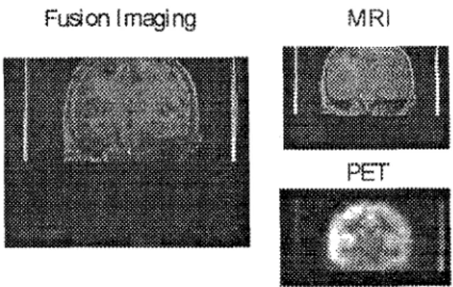
Qualitative Analysis The MRpig. 4,top left), PET(bottom left) and the fused(right) imaging are selected in a common physical coordination to qualitatively show the performance
Fig.
4The Coronal view of N-bar landmarks
of this registration technique. Two lines in M R and PET images represent the pattern of the N-bar landmarks. These pictures verify that the viewing slice of M R and PET imaging are at the same physical plane. It means that their transformation parameters are accurately determined.Conclusion
This localization technique allows the fused image set to be interactively displayed friendly at arbitrary plane under WINDOWS-95 environments. The accuracy and reproducibility of slice selection and geometric localization by the technique is
within
1.5 mm and 1 '. Cliical results show that this tcchnique is very useful and accurate in diagnosis.References
1. Mark W. Wilson, lames M. Mountz. A reference system for neuroanatomical localization on hnctional reconstructed cerebral images.
JCompulAssisl Tomogr 1989;13:174-78.