Voltage-peak synchronous closing control for shunt
capacitors
K.-C. Liu N.Chen
Indexing terms: Shunt capacitor banks, Switch-closing speed, Switch-timing deviation, Voltage-zero synchronous closing, Voltuge-peak synchronous closing
Abstract: The paper presents a new synchronous closing control, the voltage-peak closing method, to reduce shunt capacitor inrush currents and- overvoltages. Switch timing and precharged voltages for energising a single capacitor bank, a back-to-back capacitor bank and a three-phase capacitor bank are presented. The effects of switch-closing speed and timing deviation are discussed. Two examples are illustrated to show the excellent performance.
1 Introduction
The switching of any capacitor bank produces over- voltages. Transient overvoltage will always occur during energisation, and will only occur during de- energisation if restrikes occur in the switching device [l]. The switching of shunt capacitor banks has become the most common source of transient voltage on many power systems. Certain switching operations can also present some potentially hazardous overvoltage condi- tions [2], not only to the capacitor bank, but to other nearby equipment such as circuit breakers and trans- formers.
Customer loads are becoming increasingly sensitive owing to a move to power electronics equipment for increased energy efficiency and flexibility. Utility cus- tomers are also adding power-factor correction capaci- tors to avoid rate penalties and further reduce energy costs. The combination of these trends is now resulting in increased customer power quality problems owing to capacitor switching events on the utility system [3]. Sev- eral methods are available for reducing energising tran- sients [4], however, not all are practical or economical.
Both preinsertion resistors and inductors have been used by circuit-breaker manufacturers to reduce voltage and current transients during the energisation of high- voltage shunt capacitor banks. The difficulty with these devices, however, is in providing sufficient energy absorption capability without greatly increasing the complexity and cost of the circuit breaker.
0 IEE, 1998
IEE Proceedings online no. 19981889
Paper first received 18th August 1997 and in revised form 12th January 1998
The authors are with the Department of Electrical Engineering, National Taiwan University of Science and Technology, 43 Keelung Road, Section 4, Taipei, Taiwan, Republic of China
Synchronous closing is another means of reducing energising transients [SI. However, the reliability requirement of the sensing device coupled with mechanical variations in the switching device under a wide range of operating conditions have delayed devel- opments.
This paper proposes a voltage-peak synchronous closing (VPSC) method to reduce capacitor energising transients. Since the current zero appears at the instant of voltage peak for a shunt capacitor in the steady state and the voltage changing rate is minimum at the same time, a shunt capacitor car1 be energised at the instant of voltage peak with a predicted capacitor voltage level to reduce or even eliminate transients. This method brings a better performance than the traditional volt- age-zero synchronous closing (VZSC) in capacitor energisation [SI.
2 The proposed synchronous closing method Assume a capacitor bank is energised by a sinusoidal alternating supply voltage v ( t ) = Vm sin(wt
+
a) where V, is the peak value of the AC voltage. The supply fre- quency is varying at the radial supply frequency, w . The inclusion of the arbitrary phase angle a permits closing of the switch at any instant in the voltage cycle. When the switch is closed, the equation expressed in terms of the current isd i ( t ) 1
L, - dt
+
;
JT
i ( t ) d t
= v ( t )where C is the capacitance of the capacitor bank and L is the effective inductance between source and this capacitor bank. Resistance is assumed to be negligible.
The instantaneous current and voltage equation of the capacitor bank can be evaluated as follows:
i(t) =
f,
cos(wt -I- a )+
[I(O) -f,
cos a] cos w,tvJt) = V, sin(wt -t- a )
+
~ ~ ( 0 ) - V, sin a cos w,t+
- [ X J ( O ) - V, cos a sin w,t (2) where I(0) andl Vc(0) are the initial values of inductor current and capacitor voltage, respectively, con is the[
1
1
1 n
233
natural frequency of the switching circuit and n is the per unit natural frequency.
W n
and n = -
1
w, = -
m
W
X , is the impedanceA of the capacitor in the fundamental frequency, I, and V , are the peak values of the funda- mental frequency components of the capacitor current and voltage, respectively.
Eqns. 1 and 2 represent the time-domain response of the capacitor current and voltage in the capacitor switching circuit. The first term is the fundamental fre- quency component. The second and third terms repre- sent the oscillatory components with a circuit natural frequency mn. The magnitude of the oscillatory compo- nents is a function of the system voltage, capacitor trapped voltage, inductor current and the switch clos- ing time.
In general, capacitors are discharged, V,(O) = 0. The worst case occurs at the time when a discharged capac- itor is energised at the instant of voltage peak, which results in a transient overvoltage nearly twice the nor- mal peak voltage.
For ideal switching, the oscillatory components of current in eqn. 1 (voltage in eqn. 2) must be zero. This can happen only when the following two conditions are simultaneously satisfied.
I ( 0 ) = fm c o s a ~ ~ ( 0 ) = Vm s i n a
In the switching circuit, the initial current is zero, I(0) = 0. The first condition of ideal switching means that the switch must be closed at a positive or negative crest of the supply voltage sinewave (i.e. a = 290"). The sec- ond condition means that the capacitor must be charged to a specific voltage level
Both ideal switching conditions must be satisfied so that the oscillatory components will disappear. Then, both the capacitor current and voltage consist of only the fundamental frequency component.
The procedure to energise a shunt capacitor bank by the proposed VPSC method is:
Step 1: Calculate the prerequisite initial voltage level of the capacitor bank via eqn. 3.
Step 2: Precharge the capacitor bank to that voltage level by a DC charging circuit.
Step 3: Close the switch at the instant of voltage peak by a synchronous closing control circuit.
A practical approximation of the ideal switching is implemented by modifying the precharging voltage level. The predicted voltage level in step 1 is replaced by the level of the system peak voltage so that the volt- age precharge device can be simplified. In other words, the capacitor bank is precharged to the level of the sys- tem peak voltage. Then, its switch is closed at the instant of voltage peak with the same polarity. The instantaneous capacitor current and voltage are
vc(t>
= Vm siii(wt+
900)+
(v,
- Vm)cos
w,t The second term on the right-hand side represents the oscillatory component brought by the capacitor pre- charged voltage being not exactly equal to the pre- dicted level from eqn. 3. The magnitude of this component is not large enough to distort its bus volt- age. Although this method is not an ideal switching it is better than the VZSC method.3
The switch timing and precharged voltages to imple- ment the VPSC for single-phase and three-phase capac- itor energisation are presented as follows.
3.
I
Single-phase capacitor energisationQuite often the capacitor bank is divided into a number of parallel sections which can be switched inde- pendently [I]. In Fig. 1 there are two sections with their switches SI and Sz. The source inductance is repre- sented by L,, while Lb represents the inductance of the local circuit comprising the two capacitors and their bus and ground connections. Resistance is assumed to be negligible.
Switch timing and precharged voltages
-Ifeeders
-
-
Fig. 1 Switching capacitors on a substation bus3.1.
I
Single bank capacitor energisation: Con- sider first the closing of switch SI. This is a single-bank capacitor switching. For ideal switching, the switch must be closed at a positive or negative crest of the supply voltage sinewave (i.e. a = +.90") and the capaci- tor must be precharged to a predicted voltage level.Fig. 2 shows the switch timing for the proposed clos- ing method. The positive going zero crossing of the voltage is used as the synchronous reference. T, is the mechanical operation time which may vary due to the operation frequency, ambient temperature and manu- facturing technique. T, is the electrical time which is adjusted to make the switch close at the expected instant of voltage peak. A capacitor can be precharged to the positive or negative voltage peak. The capacitor switch must be closed at the instant of voltage peak with the same polarity of precharged voltage.
synchronous reference
I voltage-peak
Fig. 2 Switch timing for the pvoposed switching method
3.1.2 Back-to-back capacitor energisation: Con- sider next the closing of switch S2. This is a back-to- back switching operation. We suggest that the polarity of the precharged voltage of capacitor C2 be the same as that of capacitor Cl. Thus, both switches S l and S2 are closed at the same side of the positive voltage peak or negative voltage peak so that they will not be con- fused. The precharged voltage level of capacitor C2 is equal to the system peak voltage, Vc2(0) = kV,.
3.2 Three-phase capacitor bank energisation The VPSC can be applied to the energisation of a capacitor bank in a three-phase circuit. When a capaci- tor bank is connected between one phase and another, the capacitor bank must be precharged to a line-to-line peak voltage prior to its switch being closed at the instant of the line-to-line voltage peak with the same polarity of precharged voltage.
3.2.1 Grounded
Y
connection: In a groundedthree-phase circuit, the energisation of capacitor banks connected in a grounded Y connection can be consid- ered with three single-phase circuits independently.
Fig. 3 shows the switch timing and precharged volt- ages for a grounded Y connected capacitor bank. The next positive going zero crossing of the phase A voltage is used as the synchronous reference. In order to close the three switches as soon as possible, the time differ- ences t3 - t2 and t2 - tl should be equal to d ( 3 U). The
closing time tl of switch (SW-1) is chosen at the instant of phase A-to-ground voltage peak. Therefore the pre- charged voltage level of the capacitor Cl is decided as Vc,(0) = V,. Similarly, the precharged voltage levels of C2 and C3 are decided by the relative closing time t2 and t3 as Vc2(0) = -V, and Vc,(0) = V, synchronous reference Te3 , Tm3 , Te2 , Tm2 Tel , Tmi M *I
Fig.3 Switch timing for grounded Y capacitor connection
VC,(O) = v,; VC2(O) = -VI& V C J O ) = v,
3.2.2 Ungrounded Y connection: The proposed
closing method for energising the three capacitors con- nected in an ungrounded Y connection in a three-phase circuit is shown in Fig. 4. The method comprises two steps:
Step 1: Choose any two capacitors and energise by the VPSC method with the line-to-line voltage peak across these capacitors.
Step 2: The other capacitor is energised by the VPSC method with a phase-to-neutral voltage.
The switch timing and precharged voltage of the capacitor bank connected in an ungrounded Y connec- tion is shown in Fig. 4. The next positive going zero crossing of the line-to-line voltage between phase A and B is used as the synchronous reference. In order to close the three switches as soon as possible, a time interval of nl(2 U) between tl and t2 is necessary. SW-3
IEE Puoc.-Gener. Transm. Distrib., Vol. 145, No. 3, May 1998
can be closed first since it cannot become a closed-loop circuit, then SVV-1 is closed at tl, the instant of voltage peak of phase A-to-B. Therefore the precharged volt- age levels of the two capacitors C, and C3 are Vcl(0) =
43
VJ2, Vc3(0) = -43 VJ2. 'The other closing time t2 for SW-2 is chosen at the instant of voltage peak of phase C-to-neutral and the precharged voltage level of capac- itor C2 is Vc2(0) = -1.5 V,.synchronous reference
-TeZ--Tmp - -
--
c- I m i - 4
Fig.4 Switch timing for tugrounded Y capacitor connection Vc,(O) = 0.866Vm; Vc2(0) = -l.SOOV,; VC3(0) = -0.866Vm
Fig. 5 Switch timing for delta capacitor connection Vc,(O) = 1.732Vm; Vc2(0) -1.732Vm; VC3(0) = 1.732Vm
3.2.3 Delta connection: Fig. 5 shows three capaci- tors connected in a delta connection in a three-phase circuit which can be energised, respectively, by the VPSC method with line-to-line voltages.
The switch timing of capacitor banks connected in a delta connection is shown in Fig. 5. The next positive going zero crossing of phase A-to-B voltage is used as the synchronous reference. In order to close the three switches as soon as possible, the time differences t2 - tl and t3 - t2 should be equal to 7 4 3 U). The closing time tl of SW-1 is chosen at the instant of phase A-to-B voltage peak. Therefore the: precharged voltage level of the capacitor (2, is decided as Vc,(0) = d3V,. Simi- larly, the precharged voltage levels of the capacitors C2 and C3 are decided as Vc,(0) = -43V, and Vc3(0) =
43
v,.
4 Advantages
The advantages of VPSC can be illustrated in the switch closing speed and timing deviation by the com- parison of VPSIC with VZSC.
4.
I
Closing speedA switch's con1 act velocity and dielectric characteristics are combined to form dVldt, a rate of change of the gap dielectric withstand voltage. It must always be greater in magnitude than the rate of voltage change for VZSC [5]. However, this constraint is not so strict for VPSC.
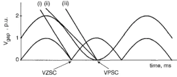
The principle requirement of the gap dielectric char- acteristics at closing is shown in Fig. 6, where the absolute value of a sinusoidal voltage is plotted for VZSC and VPSC. Lines (i) and (ii) illustrate the critical
rate of change of the gap dielectric withstand voltage for making a VZSC and a VPSC occur, respectively. As the contact closing speed increases, the rate of change of the gap dielectric withstand voltage also increases. Below a critical value, the line always crosses the AC voltage envelope, but it does not cross the expected voltage point. Above this critical value, a con- dition for making the synchronous closing occurs.
I (i)(ii) (iii) 2 3
P
Q a a 1 time, ms 0 vzs5 VPSCFig.6 Condition with contact making for VZSC and VPSC
The switch used in the VZSC method can be applied to the VPSC method, shown as line (iii). It is apparent that the slope of line (ii) is less steep than that of line (iii) so that the switch contact at voltage peak is easier than voltage zero. A vacuum switch is an excellent switch for synchronous voltage-zero closing [5]. There- fore it is certain that the vacuum switch can be applied to the proposed VPSC method.
4.2 Timing deviation
Since switches and circuit breakers are mechanical devices with complex mechanisms, the speed of opera- tion is not completely consistent. A typical deviation of 20.2ms is measured [5]. This deviation is due to the small change with temperature and the inherent mechanical inconsistency of the switch.
In order to analyse the effect of the deviation time on the voltage-zero closing and voltage-peak closing, the phase angle a in the switching capacitor current eqn. 1 is replaced by the phase angle of the expected closing point with a voltage-phase shift. The voltage-phase shift ( A u ) is proportional to the deviation time. Thus, the phase angle a = 0"
+
A u represents when the switch is closed at voltage zero with deviation time and the phase angle a = 90"+
A u represents when the switch is closed at voltage peak with deviation time.Therefore for VZSC, the current equation will be 2 ( t ) =
f,
cos(&+
Aa)
-f,
cosAa
cos w,t+
nI,
sin ACY sin w,t (4) and for VPSC, the current equation will bea(t) =
fm
cos(wt+
90"+
An) -f,
cos(90"+
Aa)
cos w,t+
nj,[sin(gO"+
~ a- )11
sinw,t (5) The last terms of eqns. 4 and 5 are dominantly the major quantities of the oscillatory component of the inrush current. Thus, we can obtain(6) The inequality indicates that the maximum peak value of the current in eqn. 4 is higher than that in eqn. 5. This results in the maximum peak value of the current of the capacitor bank energised by VPSC being less than that by VZSC when the switch is closed with devi- ation time.
I
sinAal>
I
c o s A a - 11 for 0<
Aa
<
90"The magnitudes of the high frequency oscillatory cur- rent and voltage are amplified owing to the deviation of closing time. It is more significant when the switch is closed by a VZSC method than by a VPSC method for A u < 90".
The transient magnitude of the oscillatory current versus closing time accuracy is shown for a VZSC method and a VPSC method in Fig. 7. The VPSC method has the longest allowable time deviation for a given inrush current limit. For 3p.u. oscillatory cur- rent-limit performance, the maximum time deviation for a VPSC method is 2.3ms while for a VZSC method it is 0.9ms. Even although the switch is closed exactly at voltage zero, it still brings a l.Op.u. high frequency oscillatory component. With the limitation of a 1 .Op.u. oscillatory component, the maximum time deviation for the VPSC method is 1.2ms.
'I
0 0.5 1 .o 1.5 2.0 2.5
deviation time, ms
Oscillatory current versus deviation time for VZSC and VPSC
Fig.7
methods
n = 8.0p.u.
~ voltage-zero closing
_ _voltage-peak closing ~ ~
It is more desirable for the switch to be closed late rather than early. In practice, the energisation time of 0.3 ms late is adapted by the synchronous voltage-zero closing method [5].
I _' bank 3 12MVAr
Fig.8 Example of a IISkVsystem
L, = 10mH, L,,,, = 37 6m, L,' = 20 OwH, L,' = 27 1 I.H, L,' = 27 1 pH
Table 1: Capacitor energising transients in three cases
Condition Case 1 Case 2 Case 3
Worst situation 17.03 1.98 132.04 1.55 166.70 1.45
Series inductor 17.62 1.94 51.75 1.91 56.53 1.62
VZSC method 1.99 1.05 2.18 1.04 2.21 1.04
VPSC method 1.00 1.00 1.05 1.01 1.04 1.04
5 Examples
5.
I
ExampleI:
IEEE example of a 115kVsystem
Fig. 8 shows an IEEE example of a 115 kV system [6]. The capacitor banks shown have a nominal rating of
IEE Proc -Gener Transm Dzstrib , Vol 145 No 3, May 1998 236
12MVAr and the nominal current per bank is 60A. This system is simulated by the Electromagnetic Tran- sients Program (EMTP) [7]. Three control strategies are adapted to reduce the capacitor energising transients shown in Table 1. The bus voltage in per unit is based on its system peak voltage and the maximum current in per unit is based on the peak value of the fundamental frequency current of the capacitor bank 1. For illustra- tion, the following three cases are assumed:
Case 1: Energisation of capacitor bank 1 with bank 2 and 3 not energised (isolated switching). The worst sit- uation means that capacitor bank 1 is discharged and is energised at an instant of voltage peak. This involves up to a 2p.u. overvoltage and moderate inrush current. Addition of an inductance (0.6mH) [6] is supposed to limit the inrush current but the result does not seem obvious. A large series inductor will obviously limit the inrush, but it will also reduce the capacity of the capac- itor bank and may induce a serious resonance. A syn- chronous voltage-zero closing method can reduce the energising transients efficiently, but it still brings a 2p.u. inrush current and some overvoltage. The pro- posed closing method in this paper can make a single capacitor bank energised in a transient-free switching.
2.0 1 .o -1 .o -2.0 I I , I I 1 0 10 20
Buck-to-buck capacitor energised by V Z S C method
t, ms
Fig. 9
2'o
t
bus ,'-2.01
0 10 20
Buck-to-back capacitor energised by V P S C method
t, ms
Fig. 10
Case 2: Energisation of capacitor bank 1 with bank 2 energised on the bus (back-to-back switching against an equal-size bank). Since the inductance between capacitor bank 1 and bank 2 is very small, in the worst situation, the back-to-back case involves moderate overvoltage and severe inrush current. Addition of an inductance (0.6mH) will limit the back-to-back inrush current to 52p.u., but it cannot reduce the transient overvoltage which swings between the capacitor bank and source inductance. A synchronous voltage zero closing can reduce the inrush current to 2p.u., but it brings some transient overvoltage, as shown in Fig. 9. However, the proposed closing method can energise the
IEE Proc-Cener. Transm. Distrih., Vol. 145, No. 3, May 1998
capacitor bank within minimum transients and operate as soon as possible to reach a steady state, as shown in Fig. 10.
Case 3: Energisation of capacitor bank 1 with bank 2 and 3 energised on the bus. This is also a back-to-back capacitor bank energisation. The simulation results are similar to case 2. The proposed closing method shows the best result for capacitor energisation, which has a much better performance tlhan the traditional voltage- zero synchronous closing method.
In order to analyse the effect of switch timing devia- tion on capaciitor energisation, two deviation times (0.3ms late andl l.Oms late) are assumed to be applied to the voltage-zero closing method and the proposed closing method, respectively.
Table 2 shows the maxirrtum inrush current and bus voltage when capacitor bank 1 is energised. With the same deviation time, the VZSC method will bring a larger inrush current and overvoltage than the pro- posed closing method.
Table 2: Synchronous closing with timing deviations
Condition Case 1 Case2 Case 3
VZSC w i t h 0.3ms late 3.20 1.13 15.66 1.08 19.13 1.07
VPSCwith 0.3ms late 1.12 1.00 1.50 1.01 1.14 1.02
VZSC w i t h l.Oms late 7.33 1.37 46.85 1.20 58.10 1.16
VPSC w i t h l.Oms late 2.25 1.08 9.55 1.04 11.14 1.03
The proposed VPSC method can effectively reduce the inrush current and overvoltage for the energisation of a single capacitor bank and a back-to-back capaci- tor bank. Note that the VPSC with l.Oms deviation time is even better than the VZSC with 0.3ms deviation time.
5.2 Example 2: voltage magnification
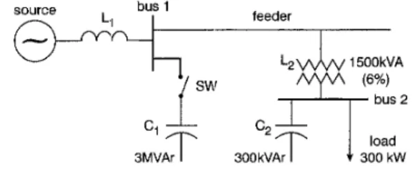
Capacitor switching transients can be magnified in cer- tain installations. One that appears to be most com- monly associated with this phenomenon occurs when capacitors are switched on from a bus switch supplying a step-down transformer that has shunt capacitors installed on the secondary side [ 3 ] . An example of an installation that may produce voltage-magnification effects is shown in Fig. 11. ]Energising the primary loop will excite the natural modes of oscillation in both the primary and secondary loops.
source
(6%)
Ny"
bus23MVAr I 300 kVAr I f 300kW
Fig. 1 1 Voltage-magnification example
Whenever capacitors are installed at multiple voltage levels, the equipment at the lower voltage level may be subjected to severe overvoll-ages even when the tuning is not exact (L1CI I L2C2).
The circuit in Fig. 11 was developed to analyse dif- ferent energising strategies 1 hat can affect this magnifi-
cation [3]. The system source at bus 1 is equal to 200MVA. A 3MVAr shunt capacitor bank is on the substation bus 1. A 15OOkVA transformer (6% imped- ance) is connected to the customer at bus 2 and a 300kVAr power factor correction capacitor and a 300kW resistive load are on the customer bus 2.
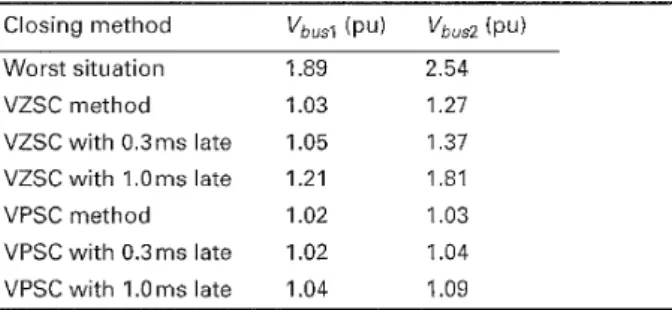
Table 3 shows the maximum voltage in per unit at bus 1 and bus 2 when capacitor C1 is energised by 7 different closing methods. In the worst situation, the discharged capacitor C1 was energised at an instant of voltage peak. It brings a 1.89p.u. overvoltage at bus 1 and a 2.54p.u. overvoltage at bus 2. The VZSC method can reduce the transient overvoltage to 1.03p.u. at bus 1 but it still brings a 1.27p.u. overvoltage at bus 2. With a deviation time, the voltage magnification at bus 2 cannot be reduced effectively by the VZSC method. With a l.Oms deviation time, the VZSC method brings a 1.81p.u. overvoltage at bus 2. However, the proposed VPSC method has a very good performance for reduc- ing the capacitor energising transients. Even with a 1.0 ms deviation time, the VPSC method still can limit the transient overvoltage at bus 2 below 1.lp.u.
Table 3: Voltage magnification produced by closing methods Worst situation 1.89 2.54 VZSC method 1.03 1.27 VZSC with 0.3ms late 1.05 1.37 VZSC w i t h l.Oms late 1.21 1.81 VPSC method 1.02 1.03 VPSC w i t h 0.3ms late 1.02 1.04 VPSC w i t h 1 .Oms late 1.04 1.09 6 Conclusions
The voltage-peak synchronous closing method can effectively reduce the energising transients for a single capacitor bank and a back-to-back capacitor bank. This method is superior to the voltage zero synchro- nous closing method in switch-closing speed and timing deviations.
The proposed method is also applied to the energisa- tion of various loads, such as the reduction of trans- former inrush current. The reduction of energising transients reduces the stresses on the switching device, extends the equipment life and improves the network power quality.
A patent on this synchronous closing control is pend- ing.
7 References
1 MILLER, T.J.E.: ‘Reactive power control in electric systems’ (John Wiley & Sons, New York, 1982)
2 ‘Impact of shunt capacitor banks on substation surge environ- ment and surge arrester applications’, IEEE Trans. Power Deliv., 1996, 11, (4), pp. 1798-1809 (IEEE, PES Surge Protective Devices Committee, WG 3.4.17)
3 McGRANAGHAN, M.F., ZAVADIL, R.M., HENSLEY, G., SINGH, T., and SAMOTYJ, M.: ‘Impact of utility switched capacitors on customer systems - magnification at low voltage capacitors’, IEEE Trans. Power Deliv., 1992, 7 , (2), pp. 862-868
4 PFLANZ, H.M., and LESTER, G.N.: ‘Control of overvoltages on energizing capacitor banks’, I E E E Trans., 1973, PAS-92, (3), pp. 907-915
5 ALEXANDER, R.W.: ‘Synchronous closing control for shunt
capacitors’, IEEE Trans., 1985, PAS-104, (9), pp. 2619-2626 6 ANSI/IEEE C37.012-1979, IEEE application guide for capaci-
tance current switching for AC high-voltage circuit breakers rated on a symmetrical current basis.
7 LEUVEN, K.U.: ‘Alternative transients program-rule book’ (Leuven EMTP Center, Belgium 1987)