Transient microstructural evolution of infrared brazed Fe
3
Al
intermetallics using aluminum foil
R.K. Shiue
a, S.K. Wu
a,b,*, Y.L. Lee
baDepartment of Materials Science and Engineering, National Taiwan University, Taipei 106, Taiwan, ROC bDepartment of Mechanical Engineering, National Taiwan University, Taipei 106, Taiwan, ROC
Received 21 July 2004; accepted 6 January 2005 Available online 14 March 2005
Abstract
The present work reports a novel approach in joining Fe3Al by infrared brazing using the pure Al as brazing filler metal. Based on the
Al–Fe binary alloy phase diagram, the species and morphology of phases as well as the transient evolution of microstructures in the infrared brazed joint are extensively studied. The Fe3Al substrate is dissolved into the molten braze, and reacts simultaneously with the Al-rich melt
during infrared brazing. Various iron aluminides such as FeAl3, Fe2Al5, FeAl2, FeAl and eutectoid FeAl2–FeAl are observed in the infrared
brazed joint for different brazing temperatures. For brazing temperatures between 700 and 1000 8C, the dendritic morphology of Fe2Al5
phase dominates the infrared brazed joint. For brazing temperatures between 1050 and 1200 8C, solid-state interdiffusion of aluminum and iron among reaction products and base metal is followed by isothermal solidification of the molten braze. Primary FeAl and eutectoid FeAl– FeAl2are widely observed in the infrared brazed joint. Further increasing the brazing temperature and/or time, the interface between the
braze alloy and substrate is finally disappeared. q2005 Elsevier Ltd. All rights reserved.
Keywords: A. Iron aluminides (based on Fe3Al); B. Bonding; D. Microstructure; E. Phase diagram, prediction
1. Introduction
With ever increasing the demand of metallic materials with better performance in specific strength, creep strength and oxidation resistance, great efforts have been focused in developing intermetallic aluminides, including iron alumi-nides, nickel alumialumi-nides, and titanium aluminides [1–4]. Because the iron aluminides are featured with low cost, low density, fairly good corrosion and oxidation resistance, they have been considered for many high temperature appli-cations. Accordingly, iron aluminides are studied compre-hensively for improved mechanical properties[1].
The development of appropriate joining processes is indispensable for using iron aluminides for structural applications. Joining of the iron aluminides is very difficult
because of their inherent brittleness at room temperature
[5–7]. For example, residual thermal stresses after welding may result in cold cracking of the weld. Welding, diffusion bonding and brazing are traditional three primary bonding processes usually applied in industry [8,9]. However, the study of welding and/or brazing in iron aluminides is still insufficient [5–7,10,11]. Vacuum brazing can offer many advantages over many other joining processes such as relatively low process temperatures, making solid joints simultaneously, dissimilar joining as well as high precision. Accordingly, it is a potential joining process in bonding iron aluminides[8,9].
For brazing intermetallic aluminides, the conventional furnace brazing with slow heating and cooling rates does not demonstrate desirable joint properties due to its long thermal history. Long thermal cycle during brazing may result in enhanced metallurgical reactions in the brazed joint, e.g. excessive growth of interfacial reaction layer(s), increased dissolution of the substrates and deteriorated strength of the base metal(s)[12–15]. Infrared brazing is a novel technique making use of infrared energy to heat up the brazed specimen, and it is characterized with a very rapid heating rate up to 3000 8C/min [16–18]. With the aid of
www.elsevier.com/locate/intermet
0966-9795/$ - see front matter q 2005 Elsevier Ltd. All rights reserved. doi:10.1016/j.intermet.2005.01.005
* Corresponding author. Address: Department of Materials Science and Engineering, National Taiwan University, Taipei 106, Taiwan, ROC. Tel.: C886 2 2363 7846; fax: C886 2 2363 4562.
solidification theory, the species and morphology of phases as well as the microstructural evolution of the infrared brazed joint are extensively examined.
2. Experimental procedure
The Fe3Al with the nominal composition of Fe–28Al (in
at%) was prepared from vacuum arc remelting (VAR) of high purity (O99.99 wt%) Fe and Al pellets for at least three times, and its total weight loss was kept below 0.1 wt% throughout the experiment [7]. The above alloy was subsequently homogenized at 1200 8C for 24 h in order to annihilate segregation of the alloy. After the homogen-ization treatment, the Fe3Al alloy was sliced into specimens
with the dimension of 10 mm(L)!10 mm(W)!2 mm(T). The infrared brazed surface of Fe3Al base metal was
polished by a SiC paper with the grit number of 600, and it was cleaned in an ultrasonic bath using the acetone as the solvent prior to infrared brazing. High purity aluminum foil (O99.99 wt%) with the thickness of 100 mm was chosen as brazing filler metal throughout the experiment. The area of aluminum foil was approximately the same size as that of Fe3Al base metal.
Infrared brazing was performed in a vacuum of 5!10K5mbar at 700, 800, 900, 1000, 1050, 1100, 1150 and 1200 8C for various time periods, respectively.
Table 1 summarized all process variables used in the experiment. The heating rate of the infrared furnace was set at 600 8C/min throughout the experiment. The speci-men was preheated at 600 8C for 90 s before heating up to the brazing temperature. Similar to the previous studies, a graphite fixture was used during infrared brazing in order to enhance the absorption of infrared
voltage of 15 kV. Quantitative chemical analysis was performed using a JEOL JXA-8600SX electron probe microanalyzer (EPMA) equipped with a wavelength dispersive spectrometer (WDS). Its operation voltage is 20 kV with the spot size 1 mm.
3. Results and discussion
3.1. Infrared brazing at 700, 800 and 900 8C
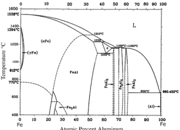
In order to unveil the microstructural evolution of the infrared brazed joint, the Al–Fe binary alloy phase diagram is cited as shown inFig. 1 [19]. According toFig. 1, several intermetallic phases can be observed from the figure, including: FeAl (23.3–55 at% Al), Fe3Al (23–34 at% Al),
3 (58–65 at% Al), FeAl2 (66–66.9 at% Al), Fe2Al5 (70–
73 at% Al) and FeAl3(74.5–76.6 at% Al)[19].
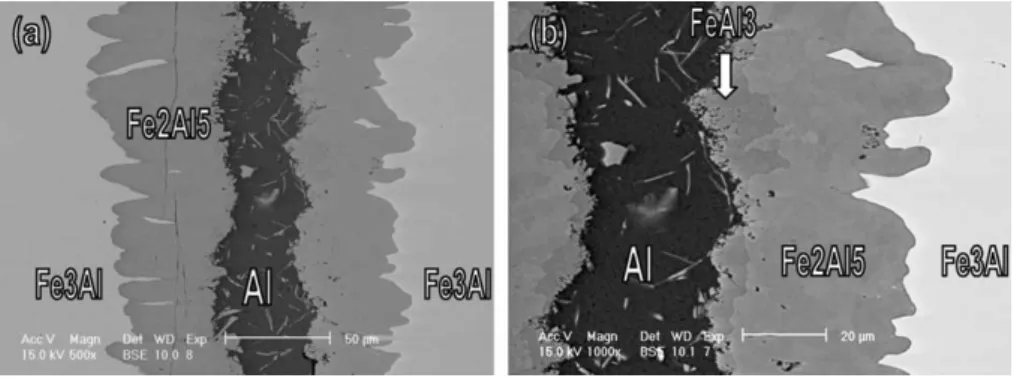
Fig. 2displays the backscattered electron images (BEIs) of Fe3Al/Al/Fe3Al specimen infrared brazed at 700 8C for
180 s. Both Al-rich and Fe2Al5(70.8 at% Al) are observed
in the infrared brazed joint as shown inFig. 2. A few FeAl3
particles are observed in the Al-rich layer. Additionally, FeAl3(75.3 at% Al) indicated by the arrow inFig. 2is also
identified at the interface between Al-rich and Fe2Al5
according to the EPMA chemical analysis result. The Fe3Al
substrate is dissolved into the molten braze, and reacts
Table 1
Process variables used in infrared brazing Fe3Al
Temperature (8C) Brazing time (s)
700 60, 180 800 15, 180 900 180 1000 180 1050 180 1100 15, 30, 45, 60, 90, 120, 180 1150 15, 30, 60, 90, 120, 180, 240 1200 15, 180
simultaneously with the Al-rich melt. Therefore, many new phases are formed after infrared brazing.
According to the Al–Fe phase diagram (Fig. 1), the FeAl3
phase is next to Al. It is expected that a mixture of Al-rich and FeAl3should be the primary phases in the brazed joint.
However, the Fe2Al5, instead of FeAl3, is the major phase in
the brazed joint, as shown inFig. 2. It is reported that the Al–Fe binary alloy phase diagram has not yet been determined completely with precision, so the refinement of reaction temperatures and phase boundaries is necessary
[19]. The dash-line shown inFig. 1demonstrates that the phase boundaries among FeAl2, Fe2Al5and FeAl3 phases
are not well defined. In addition to Fe2Al5phase in the joint,
FeAl3 phase between Al-rich and Fe2Al5 phase is also
observed in the experiment. Accordingly, phases from the center of the joint to base metal are a mixture of Al-rich and FeAl3, FeAl3(75.3 at% Al), Fe2Al5(70.8 at% Al) and Fe3Al
substrate. It is reasonable that Al contents in the above phases are decreased with increasing the distance from center of the brazed joint.
The dissolution of Fe3Al substrate into the Al-rich melt
dominates the transport of iron atoms and forms both FeAl3
and Fe2Al5 phases. It is expected that the dissolution of
Fe3Al substrate into the Al-rich molten braze is much faster
than the interdiffusion between braze alloy and substrate during infrared brazing. If the transport of Fe from the Fe3Al
substrate into the Al-rich melt is primarily dominated by grain boundary diffusion at low brazing temperatures,
the amounts of interfacial reaction layer, FeAl3 and
Fe2Al5, will be greatly decreased due to insufficient
transport of Fe atoms. Accordingly, the dendritic mor-phology of FeAl3and Fe2Al5phases shown in the brazed
joint is primarily caused by solidification of the Al-rich melt. In contrast, there is no intermediate phase at the interface between Fe2Al5 and the substrate (Fe3Al) as
displayed inFig. 2. Consequently, the solid-state interdiffu-sion between Fe2Al5and the base metal (Fe3Al) is still not
noticeable due to low brazing temperature and/or time.
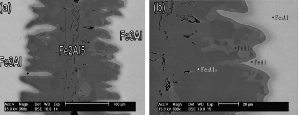
Fig. 3 shows the SEM BEIs of the Fe3Al/Al/Fe3Al
specimen infrared brazed at 800 8C for 15 and 180 s, respectively. The microstructure of the infrared brazed specimen at 800 8C for 15 s is similar to that of specimen infrared brazed at 700 8C, as compared betweenFigs. 2 and 3(a). However, the FeAl3phase is not observed anymore for
the specimen infrared brazed at 800 8C. Fe2Al5is the major
intermetallic phase in the brazed joint. As described earlier, the dash-line shown inFig. 1indicates the phase boundaries among FeAl2, Fe2Al5and FeAl3phases are not well defined
and needs further study. It is noted that the Al-rich melt is not consumed in 15 s, but it completely reacts with base metal to form the Fe2Al5compound in 180 s, as shown in
Fig. 3. Similar to the specimen infrared brazed at 700 8C, the dendritic morphology of Fe2Al5 intermetallic compound
indicates that the Fe2Al5phase is formed upon solidification
of the Al-rich melt, instead of solid-state interdiffusion between the braze and substrate.
Fig. 2. The SEM images of Fe3Al/Al/Fe3Al specimen infrared brazed at 700 8C for 180 s: (a) BEI and (b) higher magnification of (a).
Fig. 4 is the SEM BEIs of Fe3Al/Al/Fe3Al specimen
infrared brazed at 900 8C for 180 s. Compared with the aforementioned results, the Al-rich liquid is rapidly consumed during brazing due to higher brazing temperature. The EPMA identification of various phases across the joint demonstrates the presence of Fe2Al5, FeAl2 and FeAl
phases, and the Fe2Al5phase still dominates the infrared
brazed joint. Accordingly, the atomic percent of Fe is increased from the center of the brazed joint into the base metal. The dendritic morphology of Fe2Al5is very similar to
the previous cases. In contrast, the formation of minor FeAl2
and FeAl phases at the interface between Fe2Al5and Fe3Al
substrate can be primarily attributed to the solid-state interdiffusion between the braze alloy and substrate. As the brazing temperature is increased, diffusive transport of Fe atoms from the substrate into the braze alloy is greatly enhanced. Accordingly, the interdiffusion among various phases in the joint is not prominently observed until the specimen infrared brazed above 900 8C.
3.2. Infrared brazing at 1000 and 1050 8C
Fig. 5 shows the SEM BEIs of the Fe3Al/Al/Fe3Al
specimen infrared brazed at 1000 8C for 180 s. Additionally, the EPMA analysis results from the base metal (Fe3Al) to
the center of the braze joint are also included. Similar to the specimen infrared brazed at 900 8C (Fig. 4), the brazing filler metal is readily consumed for the specimen infrared brazed at 1000 8C. There are three major phases in the brazed joint, including: Fe2Al5, FeAl2and FeAl. The mass
transport of both Fe and Al atoms between the Fe3Al
substrate and Al-rich melt plays an important role in evaluating phase evolution of the brazed joint. According to
Fig. 1, the melting points of Fe2Al5, FeAl2and FeAl phases
exceed 1160 8C, and the current brazing temperature is
Fig. 4. The SEM images of Fe3Al/Al/Fe3Al specimen infrared brazed at 900 8C for 180 s: (a) BEI and (b) higher magnification of (a).
Fig. 5. The Fe3Al/Al/Fe3Al specimen infrared brazed at 1000 8C for 180 s,
SEM BEI overview of the cross-section and EPMA identification of the phases from the left side base metal to the center of the joint.
Fig. 6. The SEM BEI of Fe3Al/Al/Fe3Al specimen infrared brazed at
1000 8C. In other words, the molten braze was isothermally solidified and both Fe2Al5 and FeAl2 are formed during
brazing if the Fe content in the molten braze exceeds about 12 at%.
Because the Al–Fe binary phase diagram is not precisely defined in compositions between 65 and 76 at% Al, it
can only provide a first approximation of explanation in the experiment. Compared with specimens infrared brazed below 900 8C, the transport of Fe atoms from base metal into the braze is significantly increased at 1000 8C. For the specimen infrared brazed at 1000 8C, the gradually decrease of Fe content in the Fe3Al substrate with increasing
Fig. 7. SEM BEIs and EPMA chemical analysis results of the Fe3Al/Al/Fe3Al specimen infrared brazed at 1100 8C for (a) 30 s, (b) 45 s, (c) 90 s and (d) 120 s.
FeAl2 phase is observed, and the width of Fe2Al5 in the
center of braze is decreased due to the equilibrium promoted by thermal activation.
3.3. Infrared brazing at 1100, 1150 and 1200 8C
Fig. 7(a)–(d) display the results of SEM BEIs and EPMA chemical analysis of Fe3Al/Al/Fe3Al specimen
infrared brazed at 1100 8C for 30, 45, 90 and 120 s, respectively. The microstructure of 1100 8C brazed
dominate the infrared brazed joint, as shown in
Fig. 7(d). According to the Al–Fe phase diagram, there is a eutectoid reaction at 1102 8C as below [19]:
3/ FeAl C FeAl2 (1)
Formation of the 3 phase from the melt should exceed 1169 8C, which is much higher than the brazing temperature, 1100 8C. The discrepancy between 1169 and 1100 8C can be attributed to the exothermic reactions of the iron aluminide formation[20]. Since the ordering process of iron aluminides
Fig. 8. SEM BEIs and EPMA chemical analysis results of the Fe3Al/Al/Fe3Al specimen infrared brazed at 1150 8C for (a) 15 s, (b) 30 s, (c) 60 s (d) 90 s and (e)
is exothermic, the temperature of the braze alloy is higher than the set one during brazing. Therefore, the filler metal is usually the hottest spot, and the substrate is not as hot as the braze alloy. If the braze alloy is heated over 1169 8C, the formation of 3 phase during brazing is possible. Additionally, higher brazing temperature promotes both the dissolution rate of the substrate and the mass transport efficiency of Fe and Al atoms. Consequently, eutectoid FeAl–FeAl2phase is predominately
observed inFig. 7(b)–(d).
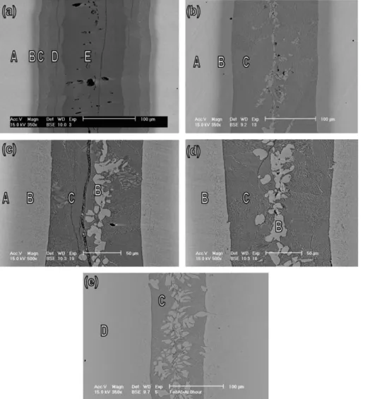
As the brazing temperature increases to 1150 8C, greater dissolution of the Fe3Al substrate into the molten braze is
expected, and more Fe content is dissolved into the 3 phase. Accordingly, hypoeutectoid reaction of 3 phase is observed in the experiment. Fig. 8(a) is the BEI of Fe3Al/Al/Fe3Al
specimen brazed at 1150 8C for 15 s. The phases in the brazed joint from center to base metal are Fe2Al5(E), FeAl2
(D), eutectoid FeAl–FeAl2 (C), FeAl (B) and Fe3Al
substrate (A), respectively. The microstructural evolution of the infrared brazed joint continuously proceeds with increasing the brazing time as displayed in Fig. 8. The microstructure of the joint is stabilized for specimen brazed at 1150 8C for 60 s. Primary FeAl phase and eutectoid FeAl–FeAl2 matrix are observed in Fig. 8(c). The
microstructure is stabilized even annealed at 720 8C for 12 h, and no clear change in microstructure is observed in the experiment. Accordingly, both primary FeAl and eutectoid FeAl–FeAl2 matrix are identified in the EPMA
chemical analyses.
Fig. 9shows the BEI of Fe3Al/Al/Fe3Al specimen brazed
at 1200 8C for 15 s. Hypoeutectoid microstructure of the infrared brazed joint is observed in the figure. Primary FeAl phase and eutectoid FeAl–FeAl2matrix are similar to those
observed inFig. 8(c)–(e).Fig. 10shows the SEM overview of the cross-section and EPMA identification of the phases in the brazed joint. It is clear that only FeAl and Fe3Al base
metal are found in the joint. The smooth transition of elemental distribution in the brazed joint demonstrates strong interdiffusion between Al and Fe during infrared brazing.
Fig. 9. Backscattered electron image (BEI) of Fe3Al/Al/Fe3Al specimen
infrared brazed at 1200 8C for 15 s.
Fig. 10. Fe3Al/Al/Fe3Al specimen infrared brazed at 1200 8C for 180 s: (a) SEI, (b) BEI overview of the cross-section and (c) EPMA identification of the
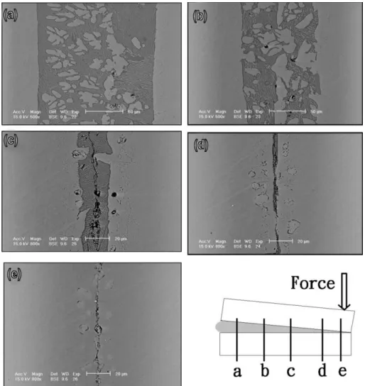
With the aid of changing the width of filler metal, the microstructural evolution of infrared brazed joint can be thoroughly observed at a single brazed joint [21]. Fig. 11
shows SEM BEIs overview of Fe3Al/Al/Fe3Al cross-section
infrared brazed at 1200 8C for 15 s with various widths of aluminum filler metal. The force is applied at one side, and the other side is kept free of any forces during infrared brazing, as shown inFig. 11. Because the formation of iron aluminides results in the depletion of Al content from the brazed joint, types of the iron aluminides formed in the joint mainly depend upon the aluminum content. A wide brazing clearance contains more Al than a narrow one. Accordingly, the brazed joint with wide clearance displays primary FeAl and eutectoid FeAl2–FeAl (Fig. 11(a)–(c)). In contrast, the brazed joint with
narrow clearance is mainly dominated by FeAl matrix due to the insufficient Al content in the brazed joint (Fig. 11(d)–(e)). It is consistent with the aforementioned results.
The infrared brazed joint will continuously move toward its equilibrium state if the specimen is further annealed. For the specimen sizes used in this study, the Al concentration in the brazed joint will increase from about 28 at% Al to about
29 at% Al as the Al foil is slowly absorbed into the Fe3Al
substrates.
3.4. Discussion
The Al-rich liquid composition will quickly approach that given on the Fe–Al binary diagram. As the temperature increases from 700 to 1100 8C, the liquid will become increasingly enriched in Fe. The FeAl3forms from the melt
when the Al-rich liquid solidifies. Additionally, the Fe2Al5
phase is also observed in the brazed joint. For the specimen infrared brazed between 1050 and 1200 8C, solid-state interdiffusion of aluminum and iron among reaction products and base metal is followed by isothermal solidification of the molten braze. The amount of both FeAl2and Fe2Al5is greatly
decreased with increasing the brazing temperature and/or time. In contrast, primary FeAl and eutectoid FeAl–FeAl2
matrix are widely observed in the infrared brazed joint. Because FeAl3, Fe2Al5 and FeAl2 phases are very
brittle, cracks can be observed in Figs. 4–6 and 8(a) and (c). It is reported that only FeAl and Fe3Al phases can
behave certain degree of ductility [1–3]. From the viewpoint of brazing technology, it will be preferred that stable and ductile phase(s) are formed in the brazed joint. Because only FeAl and Fe3Al demonstrate certain
degree of ductility, it is preferred that Fe3Al and/or FeAl
are the major phase(s) in the infrared brazed joint. Based on the experimental observation, a stable FeAl phase can be obtained for the specimen infrared brazed at 1200 8C for 180 s. Additionally, it is well known that Fe3Al is a
non-stoichiometric compound, and the solubility of Al in Fe3Al phase is between 23 and 34 at%. It is consistent
with the experimental observations in Figs. 5, 7 and 10. The smooth transition of Al, Fe contents from Fe3Al to
FeAl is demonstrated in both SEM observation and EPMA chemical analysis (Fig. 10). However, evaluation of its mechanical strength is beyond the scope of this research. It needs further study in the future.
4. Conclusions
The transient microstructural evolution of infrared brazed Fe3Al intermetallics using the pure aluminum foil
is evaluated in the experiment. The Fe3Al substrate is
rapidly dissolved into the molten braze, and reacts simultaneously with the srich melt during infrared brazing. Various iron aluminides such as FeAl3, Fe2Al5,
FeAl2, FeAl and eutectoid FeAl–FeAl2 are observed in
the joint for different brazing conditions. For brazing temperatures between 700 and 1000 8C, the dendritic morphology of Fe2Al5 phase dominates the infrared
brazed joint. In contrast, the formation of minor FeAl2
and FeAl phases at the interface between Fe2Al5 and
Fe3Al substrate can be primarily attributed to the
solid-state interdiffusion between the braze alloy and Fe3Al
substrate. For brazing temperatures between 1050 and 1200 8C, solid-state interdiffusion of aluminum and iron among reaction products and base metal is followed by isothermal solidification of the molten braze. The dendritic morphology at the interface between Fe3Al
and braze alloy becomes less noticeable. The amount of both FeAl2 and Fe2Al5 is greatly decreased
with increasing the brazing temperature and/or time.
In contrast, primary FeAl and eutectoid FeAl–FeAl2
matrix are widely observed in the infrared brazed joint. For the specimen infrared brazed at 1200 8C for 180 s, it can result in a stable FeAl phase in the joint, and the interface between the braze alloy and substrate is finally disappeared.
Acknowledgements
The authors gratefully acknowledge the financial support from National Science Council (NSC), Republic of China, under the grant NSC 89-2218-E002-071.
References
[1] Liu CT, George EP, Maziasz PJ, Schneibel JH. Mat Sci Eng A-Struct 1998;A258:84.
[2] Deevi SC, Sikka VK, Liu CT. Prog Mater Sci 1997;42:177. [3] Deevi SC. Intermetallics 2000;8:679.
[4] McKamey CG, Maziasz PJ. Intermetallics 1998;6:303.
[5] Fasching AA, Edwards GR, David SA. Sci Technol Weld Joining 1997;2:167.
[6] Fasching AA, Ash DI, Edwards GR, David SA. Scripta Metall 1995; 32:389.
[7] Lee YL, Shiue RK, Wu SK. Intermetallics 2003;11:187.
[8] Schwartz M. Brazing: for the engineering technologist. New York: Chapman & Hall; 1995 p. 1–59.
[9] Humpston G, Jacobson DM. Principles of soldering and brazing. Materials Park: ASM International; 1993 p. 1–5.
[10] Patterson RA, Martin PL, Damkroger BK, Christodoulou L. Weld J 1990;69:39s.
[11] Baeslack WA, Mascorella TJ, Kelly TJ. Weld J 1989;68:483s. [12] Shiue RK, Wu SK, Chen SY. Acta Mater 2003;51:1991–2004. [13] Shiue RK, Wu SK, Chen SY. Intermetallics 2004;12:929–36. [14] Shiue RK, Wu SK, Hung CM. Metall Mater Trans 2002;33A:
1765–73.
[15] Liu CC, Ou CL, Shiue RK. J Mater Sci 2002;37:2225–35. [16] Shiue RK, Wu SK, Chan CH. J Alloys Compd 2004;372:148–57. [17] Yang TY, Wu SK, Shiue RK. Intermetallics 2001;9:341–7. [18] Shiue RK, Wu SK, O JM, Wang JY. Metall Mater Trans 2000;31A:
2527–36.
[19] Massalski TB. Binary alloy phase diagrams. Materials Park: ASM International; 1990 p. 147–8.
[20] Kubachewski O, Alcock CB, Spencer PJ. Materials thermochemistry. 6th ed. New York: Pergamon Press; 1993 p. 163.