ELSEVIER Fuzzy Sets and Systems 95 (1998) 23 38
FUZZY
sets and systemsAn approach to simplify the learning space for robot
learning control 1
Kuu-young Young*, Cheng-Chu Fan
Department of Control Engineerin 9, National Chiao-Tung University, Hsinchu 300, Taiwan Received March 1996; revised September 1996
Abstract
Although learning controllers are considered to be capable of generalization, most robot learning control schemes either need to include conventional controllers, or need to repeat the learning process each time a new trajectory is encountered. The main reason for this deficiency is that the learning space for executing general motions of multi-joint robot manipulators is too large, In this paper, we propose an approach, motivated by the equilibrium-point hypothesis in human motor control, to simplify the learning space when learning controllers are used to govern robot motions. In the proposed approach, the motion command is formulated in the form of three square pulses in alternate directions with adjustable heights and widths. When the motion command is specified in this simple form, the learning space for dealing with variations exhibited in different movements is dramatically simplified. Thus, we can then implement a fuzzy system for robot motion control, which generates appropriate controlled parameters for the motion commands by using a reasonable number of rules. Theoretical analyses and simulations are performed to demonstrate the feasibility of the proposed approach. @ 1998 Elsevier Science B.V.
Keywords: Robotics; Learning control; Learning space simplification; Human motor control; Fuzzy system
1. Introduction
Compared to conventional controllers, learning controllers are capable o f tackling highly complex dynamics without explicit model dependence and identification. In addition, learning controllers are computationally efficient after training. Two well- known types o f learning controllers for robot mo- tion control are fuzzy systems and artificial neural networks [19,22]. The structure o f artificial neural networks is modeled after the organization o f the brain, although the similarity between the two is
Corresponding author.
1This work was supported in part by the National Science Council, Taiwan, under grant NSC 83-0422-E-009-065.
actually slight [19]. On the other hand, fuzzy systems are meant to encode pieces o f knowledge presented by experts [10, 14, 18]. In some previous research involving the application o f these two types o f learn- ing controllers for governing a multi-joint robot manipulator, they are used as subordinates, while a conventional control algorithm, e.g., PD or PID control, is responsible for the major portion o f the control [12, 13, 15]. In this approach, the conven- tional control algorithm brings the system close to the desired state and the learning mechanism then com- pensates for the remaining error. On the other hand, some systems use learning algorithms alone to execute the control. However, although these learning con- trollers are considered to be capable o f generalization, most o f them need to repeat the learning process each
0165-0114/98/$19.00 @ 1998 Elsevier Science B.V. All rights reserved PII S0165-0114(96)00300-4
24 I~-E Young, C.-C. Fan~Fuzzy Sets and Systems 95 (1998) 23-38
time a new trajectory is encountered [9]. The main reason for this deficiency is that a huge number of training patterns will be demanded for the setup of a learning controller for executing general motions of multi-joint robot manipulators. Consequently, a neu- ral controller would consist of a number of neurons or a fuzzy system requires numerous rules. This learn- ing space problem severely hinders the application of learning control.
Learning control is biologically inspired and intended to emulate human motor control. Then, a problem that may be raised is how the human motor control system resolves the aforementioned learning space problem. The superiority of the human motor control system may be attributed to its salient control strategies and exceptional capability to make proper decisions using information from abundant and ver- satile biological sensory feedback. On the other hand, human beings are not very accurate in their move- ments. Then, an intuition is that the human motor control system may have the learning space simplified at the expense of accuracy in movements. Motivated by the intuition above and the equilibrium-point hypo- thesis in human motor control, we propose an ap- proach to trade movement accuracy for learning space simplification. In this approach, the motion command is formulated in the form of three square pulses in alternate directions with their heights and widths ad- justed according to various robot motions [ 11,20, 21 ]. With the controlled parameters in the motion com- mand being the heights and widths of the square pulses, the learning space for dealing with varia- tions exhibited in different movements is dramatically simplified. The simplification of the learning space, however, is achieved at the price of accuracy in move- ments, because continuous control signals in conven- tional robot motion control schemes are approximated by signals in the form of a series of square pulses [ 1 ]. With the learning space significantly simplified, it is then feasible to design a fuzzy system for robot motion control, which can generate the heights and widths of the square pulses in the motion command by using a reasonable number of rules. The reason that we chose to use a fuzzy system for motion command generation instead of using an artificial neural net- work is because that empirical rules and data related to biological control systems are usually described and analyzed qualitatively instead of quantitatively [5].
Therefore, a fuzzy system is a more intuitive tool than an artificial neural network. The rest of the paper is organized as follows. Biological backgrounds and re- lated discussions of the equilibrium-point hypothesis are given in Section 2. The feasibility and performance of the proposed approach and its application on robot motion control are demonstrated by theoretical ana- lyses and simulations in Sections 3 and 5, respectively. The implementation of the fuzzy system for robot motion control is described in Section 4. Finally, con- clusions are stated in Section 6.
2. Inspiration from equilibrium-point hypothesis
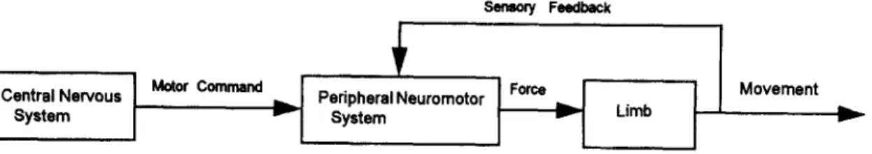
Fig. 1 shows a simplified block diagram for the neuromuscular system, which governs human limb movements. In Fig. 1, human movement is governed by a hierarchical structure [9, 17]. The central nervous system (CNS) makes movement plans according to different demands. Appropriate motor commands are then generated and sent to the peripheral neuromotor system, which modifies the motor commands via sensory feedback. The peripheral neuromotor system behaves as a local controller that adapts to different movements, loads, and environments, in addition to accepting commands from the CNS [4]. Finally, the modified commands are sent to the muscular-skeletal system for movement execution. With this hierarchi- cal structure, the difficulty of performing complex movements is shared by the CNS at the higher level and the local controller at the lower level.
The equilibrium-point hypothesis suggests that the CNS specifies equilibrium points between agonist and antagonist muscle groups that correctly posi- tion the arm in relation to the target by indicating new sets of length-tension curves for the muscle groups [3,7, 16, 17]. In other words, movement is treated as transition between postures. The CNS needs only select new levels for the motor commands. The subsequent result, mediated by autogenetic reflexes and the mechanical properties of the muscles, should be a smooth transition from one posture-state to an- other. The simplicity in the form of the control signal makes this hypothesis very attractive for motion con- trol. However, since only one equilibrium point is selected, a control strategy based on this hypothesis would not enable us even to vary the speed of the
K.-E Youn 9, C.-C. Fan~Fuzzy Sets and Systems 95 (1998) 23 38 25 Central Nervous System Motor Command Sensory Feedback
,~.J
PeripheralNeuromotor ~ LimbI
MovementFig. 1. A simplified block diagram of the neuromuscular system.
hl
h2 { Positive pulse t l t2 Negative pulse Step for equilibrium pointFig. 2. Three-pulse command pattern.
movement between two given postures. To exploit the simplicity of the equilibrium-point hypothesis and make it capable of dealing with different velocities and loads in reaching various positions, the motor command can consist of a number of equilibrium points. Thus slow movements can be produced by progressive shifts of equilibrium points. Movements can be speeded up by assigning an initial shift that is larger than necessary, followed by a return to a proper static level [7].
Motivated by the equilibrium-point hypothesis, we propose a formulation of the motion command in the form of a train of square pulses in alternate directions with their heights and widths adjusted according to the demands of different tasks. Similar concepts can also be found in [11,20]. Note that the controlled parameter in the equilibrium-point hypothesis is the muscle compliance instead of the equilibrium point used in the proposed approach. Our purpose is not to propose a new biological hypothesis, but to develop control strategies inspired from human motor control for robot motion control. In light of both physiolog- ical and engineering considerations, the number of pulses in the motion command should be kept fairly small [5, 11,20]. We propose to use three pulses
in the motion command, as shown in Fig. 2. The triphasic motion command pattern is clearly not an invariant pattern of muscle activation. The command pattern should be task, velocity, subject, and muscle dependent [5]. Nevertheless, the three-pulse motion command pattern has an engineering analogy in the bang-bang control, which is intended for fast move- ments and like the present pattern demonstrates three major force changes. The proposed command pattern also gains support from the investigation of rapid voluntary wrist movements [20], which showed that these movements normally exhibit motor commands with a three-pulse pattern for a light load: first an agonist burst, followed by an antagonist burst, fol- lowed by a second agonist burst. Correspondingly, three major alternating phases of net force were observed: a net force first in the direction of move- ment, then opposed to the movement, and finally in the direction of movement again. For a heavy load, however, the second agonist burst was not very apparent.
3. Proposed approach
According to the discussions above, when the three-pulse motion command pattern is used for robot motion control, the controlled parameters in the mo- tion command will be a constrained set with few parameters. We will then develop a fuzzy system, acting as the CNS of the neuromuscular system in Fig. 1, to generate motion commands. The controlled parameters for the proposed fuzzy system are the heights and widths of the three square pulses cor- responding to the equilibrium points in the motion command. It can be seen that the fuzzy system under design will face a small learning space. For a feasible
26 K.- Y. Young, C.-C Fan / Fuzzy Sets and Systems 95 (1998) 23-38
t
Robot dynamics
Movement
Fig. 3. Conceptual organization of the proposed control scheme.
implementation of the fuzzy system, the number of basic three-pulse command patterns for generalization will be limited. In other words, the fuzzy system will generalize a set of basic command patterns to cover a wide variety of movements. As the simplification of the learning space is at the price of inaccuracy dur- ing movement, the proposed approach demonstrates a trade-off between movement accuracy and memory utilization in learning.
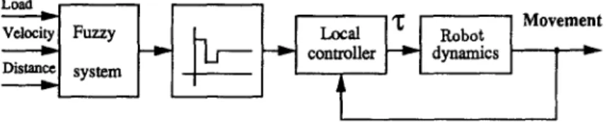
A conceptual organization of the control scheme for governing motions of multi-joint robot manipulators by applying the proposed approach is as shown in Fig. 3. The inputs to the fuzzy system are distance of movement, velocity, and load corresponding to the robot motion. In turn, the fuzzy system will generate a corresponding three-pulse motion command and send it to the local controller. The local controller will then modulate the command via sensory feedback and use the resulting signal to move the robot link. Before the implementation of the fuzzy system for the robot control scheme, we will first evaluate the feasibility of applying the three-pulse motion command pattern for robot motion control from an engineering point of view.
3.1. Feasibility analysis
The three-pulse motion command pattern (shown in Fig. 2) functions as follows: first, a large burst gen- erates a large initial speed, then a small burst brakes the movement, and finally, a step brings the limb into the equilibrium posture assigned by the CNS. In order to check whether the three-pulse motion command pattern is appropriate for controlling robot motions, we investigate the force profiles correspond- ing to various movements reaching the same distance with different loads and velocities. A simulation sys- tem is developed to derive the force profile from the
desired movement positions, velocities, and acceler- ations. Both single-joint and multi-joint movements are analyzed.
We will begin with single-joint movements. Consider the second-order system described in Eq. (1):
M£+BJc+K(x--Xd) = O, (1)
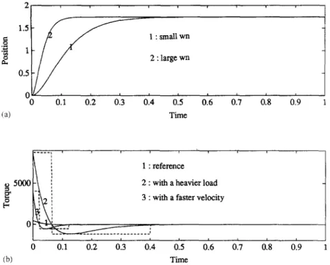
where M is the load, K the stiffness, B the damp- ing coefficient, and xd the equilibrium point. In the simulations, motion commands, and consequently the three-pulse command patterns, are introduced to the system via the assignment of the equilibrium point Xd. This second-order system can also be interpreted as having an equilibrium point at the origin and an in- put force specified by KXd. If we choose the values of K and B for a given load M properly, the system can be designed to be critically damped when the equilib- rium point is fixed, which corresponds to an applied step force. Fig. 4(a) shows two desired critically damped trajectories with different natural undamped frequencies, wn. First we conducted a simulation to see how the applied force adjusted to deal with a heavier load when the same movement profile is pre- served. The critically damped trajectory with smaller
wn was used as a reference. The evaluated force pro- file, K(Xd --x) --BYe, can be derived by using Eq. (1) and x, ;?, and 5? of the critically damped trajectory. The simulation results are shown in Fig. 4(b). The trace marked by 1 is the reference force profile when a step input is applied. The force profile corresponding to a heavier load marked by 2 exhibits a large initial bell-shaped waveform, followed by a small one in the negative direction, and finally a step at the origin. This force profile implies that the control signals are in the form of a large burst, followed by a small burst, and finally a step indicating the equilibrium point, i.e., the three-pulse motion command pattern. We performed
K.-K Young, C-C Fan~Fuzzy Sets and Systems 95 (1998) 23 38 27 ~2 (a) 2 1.5 1 0.5 0 0 0.1 . . 0.2 . .0.3 0.4 015 u wn wn I I I i 0.6 0.7 0.8 0.9 Time 5OOO (b) 0 . . . 018 ' 0 0.1 0.2 0.3 0.4 0.5 0.6 0.7 0.9 . . . 1 1 : reference
~1 2 : with a heavier load
~ik2 3 : with a faster velocity
~ _ J
Time
Fig. 4. Single-joint movement: (a) desired critically damped trajectories and (b) force profiles for a heavier load or a faster velocity.
another simulation to see how the force profile is af- fected by a larger m o v e m e n t velocity when the load and the distance o f m o v e m e n t are kept the same. In this case, the critically damped trajectory with the larger natural undamped frequency wn, which corresponds to a smaller time constant, was used as a reference for a fast movement. Consequently, the values o f K and B for this trajectory are larger than those for the previ- ous one. The desired force profile is still derived using Eq. (1); x, 2, and 5/are for the new critically damped trajectory, and the values o f K and B are those o f the previous trajectory. The resulting trace is shown in Fig. 4(b), marked by 3; the trace demonstrates a force profile similar to that in the previous case.
To extend the analysis to multi-joint movements, we need to consider dynamic interaction between joints. The dynamics o f multi-joint movements can be for- mulated as follows:
z : H(q)i~ + C(q, i l ) + G(q), (2)
where q, ~¢, and ~/stand for joint variables and their derivatives, H ( q ) is the inertia matrix, C ( q , ( l ) is
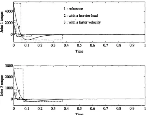
the vector o f centrifugal and Coriolis terms, G ( q ) is the vector o f gravity terms, and z is the vector o f joint torques. The effect o f gravity will be ignored in the following simulations. As we did for the single-joint movement, we generate critically damped trajectories for each o f the two joints. We performed simula- tions to see how the force profile varies with different loads, m o v e m e n t velocities, and the presence o f dy- namic interaction. Similar to the procedure for single- joint movements, the evaluated force profile can be derived by using Eq. (2) and the critically damped trajectories for the two joints. Fig. 5 shows the simu- lation results for two-joint movements with a heavier load and a faster m o v e m e n t velocity. In Fig. 5, phe- nomena similar to those in Fig. 4 are observed for both joints under different load and m o v e m e n t velocity conditions, thus providing evidence to justify use o f the three-pulse motion c o m m a n d pattern. In summary, the simulation results for single-joint and two-joint movements imply that the three-pulse motion com- mand pattern captures most o f the behavior o f robot motion.
28 K.-Y. Young, C.-C. Fan~Fuzzy Sets and Systems 95 (1998) 23-38 ~4000 0 . . . . 1 i i i . . . . j I I I 0.1 0.2 0.3 f i i 1 : reference 2 : with a heavier load
3 : with a faster velocity
I I 0'.4 015 0.6 0.7 018 019 Time 3 0 0 0 2000 1000
.
.
.
.
.
.
.
ols
o19
0 0.1 0.2 0.3 0.4 0.5 0.6 0.7 TimeFig. 5. Force profiles for two-joint movement with a heavier load or a faster velocity.
3.2. Local controller
As mentioned in the introduction o f the neuro- muscular system in Section 2, the three-pulse motion command pattern will be modified by the peripheral neuromotor system before it reaches the limb. The me- chanical properties possessed by the peripheral neu- romotor system play an important role for supporting the simple control strategies employed by the CNS. Especially when compliant motions are involved, for which different environments exhibit various stiffnesses and viscosities, the influence of the me- chanical properties is significant [8]. To replicate the mechanical properties of the peripheral neuro-motor system adequately, a complicated local controller will be needed. In tackling free motions, however, the local control system may not be so crucial. There- fore, for the purpose of simplicity we will attribute the intelligence of the proposed scheme to the fuzzy system and the three-pulse motion command pattern, and use the local controller to deal with sensory feed- back only. Because no desired velocity is specified in the three-pulse motion command pattern, we propose
a simple position control law with linear damping for this local controller:
7: = K p ( q d --
q)
- K d q ,(3)
where qd stands for the vector of the equilibrium joint positions and Kp and Kd are symmetric positive def- inite matrices. The actual positions and velocities, q and q, are obtained via sensory feedback.
3.3. Stability analysis
Another main concern of the proposed approach is stability using the three-pulse motion command pat- tern and the local controller. Since the first two pulses of the motion command pattern can be taken as the transient, we may in turn analyze the stability of the multi-joint system under step inputs and the control law described in Eq. (3). In the absence of gravity, the system dynamics described in Eq. (2) can be rewritten
as
K.-Y. Young, C.-C. Fan~Fuzzy Sets and Systems 95 (1998) 23-38 29
~sP-I Fuzzifier
-I
Input
[ Rulebase I
[Database[
I
I
i i
Inference
] f~zy
I
crisp• ~ Defuzzifier
~n~e ]
----I
~'~Output
Fig. 6. Proposed fuzzy system.
!
Lo~a ~Pu~ I-I,t.t~.h,.h2 I I ~ ' ~ [
"-]
/
Reference [
d.,, ]
Performance evaluation good~
stop
Fig. 7. Learning process for deriving reference motion commands.
where C ' = C ' ( q , q ) is a matrix and ( H - 2 C ' ) is antisymmetric [1]. Consider a Lyapunov function candidate
V ~(qeKpqe + 1 T qTHq), (5)
where qe = qd -- q. After some manipulation using Eqs. ( 3 ) - ( 5 ) , we obtain
: -- ¢iTKd¢i ~ 0 . (6)
Thus the system is proved to be stable using the three-pulse motion command pattern and the local controller.
4. Implementation of the fuzzy system
In order to realize the robot control scheme in Fig. 3, we need to implement a fuzzy system for generating proper three-pulse motion commands according to dif- ferent distances, velocities, and loads. As four vari-
ables, hi,
h2, tl, and t2, need to be assigned for themotion command as indicated in Fig. 2, there will be three inputs and four outputs for this fuzzy system. We will first develop a fuzzy system to control a second- order system. Later, to control multi-joint movements, the fuzzy system for the second-order system will be applied to each of the joints via proper scaling. To deal with dynamic interaction present in multi-joint movements, in some sense our design takes advantage of the fuzzy relation incorporated in the fuzzy rules via open-loop control. It can be seen that the compen- sation effect via the robustness of the fuzzy system will diminish along with the increase of the number of joints. At the current stage of the study, we do not intend to develop a fuzzy system that can govern general motions of multi-joint robot manipulators. In- stead, we will concentrate on demonstrating the effect of the combination of the proposed motion command pattern and the fuzzy system in learning space simpli- fication and coverage.
30 K.-K Young, C . - C Fan~Fuzzy Sets and Systems 95 (1998) 23~8 Membership (a) MS1 MS2 MS3 M M I MM2 MM3 MB1 MB2 MB3 I I O.O5 O.5O 1 ~ l x C M Membership v s l v s 2 v s 3 v s 4 VMI VM2 VM3 VM4 VFI ~ VF3 I I 03175 0.6350 0.9524 I X C V X Distance (b)
Fig. 8. Membership functions for (a) load and (b) velocity.
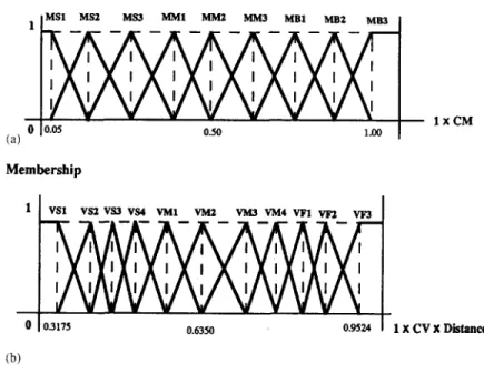
Fig. 6 shows the structure of the proposed fuzzy system. The system will function as follows: first, the crisp inputs are fuzzified through a fuzzifier, then the fuzzy data are processed by an inference engine which takes information from the rule base and data base, and finally, they are defuzzified to obtain the crisp outputs. Note that, although three inputs - distance, velocity, and load - are called for in this fuzzy system, only velocity and load are input to the fuzzifier. This is be- cause the input distance will be directly proportional to the final step of the three-pulse motion command under the equilibrium-point hypothesis and so it re- quires no further processing. In order to construct this system, proper membership functions need to be de- rived for the fuzzifying process. In addition, the rule base and data base, representing the fuzzy reasoning process, have to be developed. Therefore proper mo- tion command patterns corresponding to various con- ditions need to be provided, so that the membership functions, rule base, and data base can be implemented according to these reference commands.
We will generate the reference commands by engineering means, instead of collecting data by
performing extensive experiments on human limb movements. In our design, the reference motion command patterns are derived by a learning pro- cess, as shown in Fig. 7. In Fig. 7, various com- binations of tl, t2, hi, and h2 are first assigned for the three-pulse motion commands. Then the com- mands are sent to move the links. In turn, the performance of the movement solicited is eval- uated by comparing it with the desired move- ment profiles. The desired movement profiles are generated by adjusting the values of K and B to make the linear second-order system, de- scribed by Eq. (1), behave as critically damped under different distance, velocity, and load con- ditions. These procedures will be repeated until enough sets of motion commands are obtained for various distance, velocity, and load condi- tions.
By utilizing these sets of motion commands as references, we can implement the fuzzy system. We assign 99 rules for each of hi,
h2,
tl, and t2. These rules are defined as fuzzy conditional statements of the form given in Eq. (7):K.-Y. Youny, C.-C. Fan~Fuzzy Sets and Systems 95 (1998) 23-38 31 8 ;> 2 1,5 1 0.5 ~ 0 0 30 20 10 0 0 small m a s s i
F
i0'.5
i
1.5
Time small mass i i i 0.5 1 1.5 Time "I:17,
(a. > 2 2 large,mass 1.51 0.5: 0 0 0.5 1 1.5 Time 0 large,mass 015 1 ' 1.5 ' Time 10 O small mass -5 100 50 large,mass i - - i 0 05 0 0.5(a) Time Time
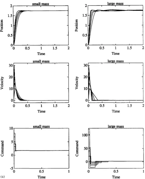
Fig. 9. Performance of the fuzzy system for a second-order system under (a) different velocity requirements and (b) different load requirements.
I F load is Ai A N D velocity is Bj T H E N h]is Ci, j, I F load is Ai A N D velocity is Bj T H E N h2 is Di.j, I F load is Ai A N D velocity is Bj T H E N tl is E~,j, IF load is Ai A N D velocity is Bj T H E N t2 is Fi, j,
(7)
where i = 1 , . . . , 9, j = 1,..., 1 l, and Ai, Bi, Ci, j, Di, j,
Ei,/,
and F/, j are fuzzy sets. In combining fuzzy rules, we adopt the commonly-used max-min composition[22].
The triangular membership function is used for the input fuzzy sets, as described below:
,4x)
32 K-Y. Young, C-C. Fan~Fuzzy Sets and Systems 95 (1998)23-38 1.5 ~'~ 1 a ~ 0.5 0 0 ;> slow v,clocity
:
10 0 0 i i i 0.5 1 1.5 2 Time slow v,el(x~ity L ! I 0.5 1 1.5 Time > 2 1.5 1 0.5 0 0 30 2O I0ok
0 , fast velocity 015 I ' 1.5 ' Time fast velocity , I I a 0.5 1 1.5 Time O (b) 20 10 slow v,eloc~ 0 : I 0 015 Time 100 50 fast velocity° 3
L 0 0.5 Time (b - Ix - a l ) / b u ( x ) = (c Ix - a l ) / c 0 i f a - b < ~ x < a, i f a < ~ x < a + c , otherwise. Fig. 9. Contd.(8)
Different membership grades at the same crisp point can be obtained by adjusting parameters a, b, and c. The membership functions o f output fuzzy sets are chosen as fuzzy singletons. A fuzzy singleton is a fuzzy set F whose support is a single point in a uni- versal set ( U ) with UF = 1.0 [10]. For a defuzzifica- tion strategy, we shall adopt the center o f area method (COA), which generates the center o f gravity o f the possibility distribution o f a control action. In the case
o f discrete universe sets, this method yields
n
X* -- ~ i : 1 U(Xi)Xi ( 9 )
l u ( x i )
where n is the number o f quantization levels o f the outputs. The ranges for the input variables are
load E [1,20] and velocity c [10,30] when the dis- tance is equal to 1.75. The range o f velocity will be further adjusted directly proportional to the distance, because intrinsically, the equilibrium point corre- sponding to a larger distance will induce a larger velocity. Fig. 8 shows the membership functions for both load and velocity. In Fig. 8, constants CV and
K.-Y. Young, C-C Fan~Fuzz), Sets and Systems 95 (1998) 23-38 33 Z i a d M g ~ x (a) Load M I2 I / l l l l l (b)
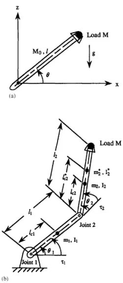
Fig. IO. (a) A single-joint manipulator and (b) a two-joint manipulator.
CM are equal to 18 and 20, respectively. These two constants are used to make the fuzzy sets correspond to the input-output ranges.
We performed a series of simulations to demon- strate the performance of the fuzzy system for a second-order system. Fig. 9(a) shows the system's behavior in reaching the same distance under different velocity requirements. Two loads, one a small mass and one a large mass were simulated. The system performed well in both cases; the curves for the small mass are smoother. It can be seen from the figure that the heavy load involves commands with larger mag-
nitudes, as expected. Fig. 9(b) shows the system's behavior as it reaches the same distance under differ- ent load requirements. Both slow and fast velocities were simulated, and the system again performed well in both cases. As expected, the case of fast velocity involves commands with larger magnitudes.
5. Simulations
We executed simulations for single-joint and two- joint movements. The performance of the single-joint movements can be expected to be similar to that of the fuzzy system for a second-order system in Section 4. The performance of the single-joint movements will serve as a reference for evaluating that of the two- joint movements. In two-joint movements, we dealt with both whipping and reaching movements and the related dynamic coupling.
5.1. Single-joint movements
The dynamic equation for a single-joint manipu- lator, as shown in Fig. 10(a), can be expressed as follows:
I0 + Bi 0 + #g cos (0) = z, (10)
where I = 1 gmol + Ml 2, U =l(½Mo + M), 34o= 2 2.815 kg is the mass of the link, M is the load, l = 0.3 m is the manipulator length, BI is the damping coefficient, and the center of mass is located at the middle of the link. If the single link moves in a hori- zontal plane with input torque z = - Ko0 - K p ( O - 0 0 )
provided by the local controller, the dynamic equation in Eq. (10) can be rewritten as
I0 + BdO + Kp(O - 0 0 ) = 0 , (11)
where Kp and Kd are constants for the local controller, Bd = Kd + B~, 0 is the actual joint value, and 00 is the joint variable specified by the motion command. The values of Bo and Kp in Eq. (11 ) can be obtained via a linear scaling of the B and K used in the fuzzy sys- tem for a second-order system by comparing the iner- tia in Eq. ( 11 ) with the load used in the fuzzy system. The scaling Of Bd( =Kd + B1 ) and Kp in some sense implicates the adjustment of Kd and Kp of the local controller for matching the system's operating range. The simulation results are shown in Fig. 11. Fig. 1 l(a)
34 K.-Y. Young, C - C Fan~Fuzzy Sets and Systems 95 (1998) 23-38
!
(a) 2 no load 1 0.5 0 0 0.5 1 1.5 30 2O 10 0 0 ~e(soc) no load. t ! 1.5 1 0.5 0 2 0 0.5heav~
load 3oii
1'.5
Tim~)
heav~ load~ ,0
0 I I Io15
~
~;
2
o
o;
1
1.5
Time(sec) Time(sec)i
(b) 2 1 0.5O0
015 10 0 ,-- 0 015slow v,elocity fast velocity
L - , 1.5 1 0.5 ' ' 0 ' ' ' I 1.5 2 0 0_5 1 1.5 Time(sec) Time.(sec)
slow velocity fast velocity
> 0
I I I I I
1 1.5 2 0 . 5 1 1,5
Time(sec) Time(sec)
K.-E Young, C.-C. Fan~Fuzzy Sets and Systems 95 (1998) 23 38 35 2 1 0 -11 -2 0 3 2.5 2 1.5 Joint 1, (1.75)
/
i i i 0.5 1 1.5 2 Time(see)i
2 1 0 -1 -2 Joint 2 (1.75)#
io15
i
15
Time 2.5 1 i i 0.5 0 0.5 Time Time (a) i 0.5 ! -0.5Cartesim position
,Caztesian,
velocity0 " - -
-10 -
i i L i i L
-0.5 0 0.5 0 0.5 1 1.5
X_.position(m) Time
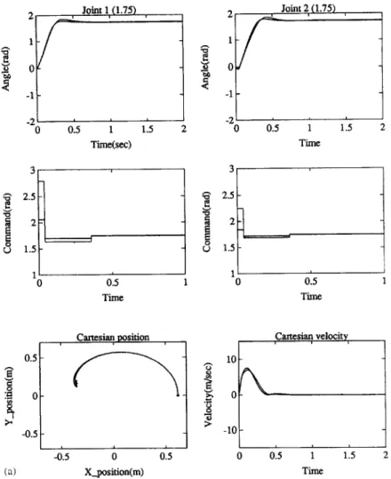
Fig. 12. Simulation results for two-joint movements: (a) whipping action and (b) reaching action.
shows the performance in reaching the same distance under different velocity requirements with no load and with a heavy load. Fig. 1 l(b) shows the performance in reaching the same distance under different load re- quirements using slow and fast velocities. The sys- tem's behavior in these simulations is similar to that shown in Fig. 9.
5.2. Two-joint m o v e m e n t s
In the simulations for two-joint movements, first we need to map the distance and velocity from Cartesian to joint space by solving the inverse kinematics. The distance o f movement and the velocity for the individ- ual joint can then be obtained. The values o f Kd and
Kp in the local controllers will also be adjusted fol- lowing the procedure in the simulation for single-joint movements. However, because the inertias for the two joints are varying and dynamic coupling are present during two-joint movements, the "equivalent inertias" o f the two joints used for the scaling o f Kd and Kp will be in the middle range o f the varying inertias plus the effect o f the dynamic coupling.
The dynamic equations for a two-joint planar manipulator, as shown in Fig. 10(b), can be expressed as follows
r, = H I l O , + H1202 - HO~ - 2H0",0'2 + G], (12) ~z =H2101 4-H2202 4- HO} 4- G2, (13)
36 K.-E Young, C-C. Fan~Fuzzy Sets and Systems 95 (1998) 23 38 Joint 1, ( t .75) 2
1/1"
o -1 -2 o!
i i i 0.5 1 1.5 2 Time(sec) -1.2 -1.4 -1.6 -1.8 2, , Joint 2,(-1,75) 20 0.5 1 1.5 Time 3 2.5 2 1.5 1 0 i 0.5 Time -2 0 i 0.5 Time (b) 0.4 0.2 0 -0.2 0Cartesian po, siaon 1{3 ,Cartesian, velocity,
%
0'2 014 016 X_position(m) >, 5 -5 "10 b 015 1 i Time Fig. 12. Contd. 1'.5 2 where H~j = m112cl + 11 , 2 ,2+ m 2 [ l l + It2 + 2lllc2 cos(02)] + I2", • ,.2 +/2* ' H22 ~--- m2 tc2 • • • .2 • H12 = m2 Ii l~2 cos(02) + m 2 lc2 + I~, Hzl = H12, H = m~ll 1c2 sin(02), GI = ml lcl g cos(01 ) + m ~ g [lc2 cos(0l + 02) + ll cos(01 )], (14)
(15)
(16) (17)(18)
(19) G2 = m~Ic*2 9 c o s ( 0 1 + 02) (20) and m~ = m2 + M, (21 ) m2 lc2 + M12 l~2 = , (22) m2 I~ = 12 + m2(l* 2 - / c 2 ) 2 + M(12 - / ' 2 ) 2, (23) with mt = 2 . 8 1 5 k g , m 2 = 1.640kg, ll = 0 . 3 0 m , 12 = 0 . 3 2 m, lct = 0 . 1 5 m, lc2 = 0 . 1 6 m, and It = / 2 = 0.0234 kg m 2.The effect o f gravity was ignored in the simulation, since these two links were assumed to m o v e in a hori- zontal plane. In the presence o f d y n a m i c coupling, the
K.-Y. Youn9, C.-C. Fan~Fuzzy Sets and Systems 95 (1998) 23 38 37 two-joint movements will be divided into whipping
and reaching actions [6]. A whipping action involves flexion o f the upper and lower links in the same direction; a reaching action involves flexion o f two links in opposite directions. These two actions induce different coupling effects. W e simulated whipping actions with two different loads; the corresponding traces overlap, as shown in Fig. 12(a). Since the two links rotate in the same direction, the joint velocities o f the two joints have the same signs. The induced dynamic coupling can be deduced from Eqs. ( 1 2 ) - (13) [6]. In Fig. 12(a), the position trace in Cartesian space is a curve with a small hook near the destina- tion. Fig. 12(b) shows the simulation results for the reaching action. In this case, the two links move in opposite directions, so the Coriolis and centripetal torques have a diminished influence c o m p a r e d with their influence on a whipping action. In Fig. 12(b), the reaching m o v e m e n t demonstrates a straighter position trace than the whipping movement. The simulation results in both cases show that the motion c o m m a n d s generated b y the fuzzy system possess certain degree o f robustness and can still yield stable and smooth Cartesian trajectories in the presence o f dynamic coupling.
6. Conclusions
In this paper, we proposed an approach to simplify the learning space for robot learning control. Theo- retical analyses and simulations demonstrate the fea- sibility o f our approach. A t the current stage o f the study, a robot control scheme based on the p r o p o s e d approach is not available for application on general industrial robot manipulators. Nevertheless, the com- bination o f the p r o p o s e d m o t i o n c o m m a n d pattern and the fuzzy system leads to learning space simplifica- tion and coverage, and is with a potential to achieve the goal o f governing general industrial robot manip- ulator by using the learning m e c h a n i s m as the main control module. Future study will concentrate on tack- ling dynamic interactions present in motions o f multi- joint robot manipulators. A n o t h e r worthwhile task will be to develop a more intelligent fuzzy system to ap- proximate the reasoning process o f an expert, such that the fuzzy system can deal with inputs b e y o n d the specified range and refine itself from inputs, in
addition to the generalization o f the reference motion c o m m a n d s [2].
References
[1] J.J. Craig, Introduction to Robotics (Addison-Wesley, Reading, MA, 19893.
[2] S. Dutta and P.P. Bonissone, Integrating case- and rule- based reasoning, lnternat. J. Approx. Reasonin9 8(3) (1993)
163-203.
[3] T. Flash, The control of hand equilibrium trajectories in multi-joint arm movements, Biol. Cybernet. 57 (1987) 257-274.
[4] C.C.A.M. Gielen and J.C. Houk, A model of the motor servo: incorporating nonlinear spindle receptor and muscle mechanical properties, Biol. Cybernet. 57 (1987) 217-23 I. [5] G.L. Gottlieb, D.M. Corcos and G.C. Agarwal, Organizing
principles for single-joint movements 1. A speed-insensitive strategy, J. Neurophysiol. 62(2)(1989)342-357.
[6] J.M. Hollerback and T. Flash, Dynamic interactions between limb segments during planar arm movement, Biol. Cybernet. 44 (1982) 67-77.
[7] J.C. Houk and W.Z. Rymer, Neural control of muscle length and tension, in: Handbook o f Physioloyy The Nervous System II, Vol. 11 (American Physiol. Soc., Bethesda, MD, 19813 Sec. 1, Ch. 8, 257-323.
[8] J.C. Houk, C.H. Wu, K.Y. Young and L.E. Miller, Nonlinear damping of limb motion, in: Winters and Woo, Eds., Multiple Muscle Systems (Springer, New York, 1990) 214-235. [9] M. Kawato, Y. Uno, M lsobe and R. Suzuki, Hierarchical
neural network model for voluntary movement with application to robotics, IEEE Control Systems Maq. 8(2) (19883 8-16.
[10] C.C. Lee, Fuzzy logic in control systems: fuzzy logic controller - Part l, IEEE Trans. Systems Man Cybernet. 20(2) (1990) 404-418.
[11] S.L. Lehman, Input identification depends on model complexity, in: Winters and Woo, Eds., Multiple Muscle Systems (Springer, New York, 1990) 94 100.
[12] C.M. Lira and T. Hiyama, Application of fuzzy logic control to a manipulator, IEEE Trans. Robotics Automat. 7(5) (1991) 688-691.
[13] W.T. Miller IlI, F.H. Glanz and L.G. Kraft 111, Application of a general learning algorithm to the control of robotic manipulators, Internat. J. Robotics Res. 6(2) (1987) 84-98. [14] A. Nedungadi and D.J. Wenzel, A novel approach to robot
control using fuzzy logic, IEEE Internat. Conj. Systems Man Cybernet. (199l) 1925-1930.
[15] T. Ozaki, T. Suzuki, T. Furuhashi, S. Okuma and Y. Uchikawa, Trajectory control of robotic manipulators using neural networks, IEEE Trans. Industrial Electronics 38(3) (1991) 195-202.
[16] A. Polit and E. Bizzi, Characteristics of motor programs underlying arm movements in monkeys, ,L NeurophysioL 42(!) (1979) 183-194.
38 K.-Y. Young, C.-C Fan~Fuzzy Sets and Systems 95 (1998) 23-38
[17] R.A. Schmidt, Motor Control and Learning: A Behavioral
Emphasis' (Human Kinetics Publishers, Champaign, IL, 1988).
[! 8] B.A.M. Wakileh and K.F. Gill, Use of fuzzy logic in robotics,
Comput. in Indust. !0 (1988) 35-46.
[19] P.D. Wasserman, Neural Computimj - Theory and Practice (Van Nostrand Reinhold, New York, 1989).
[20] C.H. Wu, K.Y. Young, K.S. Hwang and S. Lehman, Voluntary movements for robotic control, 1EEE Control
Systems May. 12(1) (1992) 8-14.
[21] K.Y. Young and C.C. Fan, Control of voluntary limb movements by using a fuzzy system, 1EEE Conj'. Decision
and Control (1993) 1759 1764.
[22] H.J. Zimmermann, Fuzzy Set Theory and Its Applications (Kluwer Dordrecht; 3rd ed., 1996).