Hsieh and Wei: Channel Estimation for OFDM Systems Based on Comb-Type Pilot Arrangement in Frequency Selective Fading Channels
CHANNEL ESTIMATION FOR OFDM SYSTEMS BASED ON COMB-TYPE PILOT
ARRANGEMENT IN FREQUENCY SELECTIVE FADING CHANNELS
Meng-Han Hsieh' and Che-Ho We? Department
of
Electronics EngineeringNational Chiao Tung University Hsinchu, Taiwan 30050, R.O.C.
E-mail: 'meng Qclab.ee.nctu.edu.tw, *chwei @cc.ntcu.edu.tw
217
A B
s
TR ACTIn this paper, the channel estimation methods for OFDM sys- tems based on comb-type pilot sub-carrier arrangement are in- vestigated. The channel estimation algorithm based on comb- type pilots is divided into pilot signal estimation and chan- nel interpolation. The pilot signal estimation based on LS or MMSE criteria, together with channel interpolation based on piecewise-linear interpolation or piecewise second-order poly- nomial interpolation
is
studied. Owing to the MMSE estimate of pilot signals, the inter-carrier interference and additive white Gaussian noise are reduced considerably. The computational complexity of pilot signal estimation based on MMSE crite- rion can be reduced by using a simplified LMMSE estimator with low-rank approximation using singular value decomposi- tion. Phase compensators before and after interpolation are also presented to combat the phase changesof
subchannel symbols arising from the frame synchronization errors. Comparing to the transform-domain processing based channel estimation al- gorithm, the MMSE estimate of pilot signals together with phase compensated linear interpolation algorithm provides better per- formance and requires less computations.I . INTRODUCTION
Orthogonal Frequency Division Multiplexing (OFDM) tech- nique has received a lot of interest in mobile communication research lately.
For
wideband mobile communication systems, the radio channel is usually frequency selective and time vari- ant. Hereafter, in OFDM systems, the channel transfer function of radio channel appears unequal in both frequency and time do- mains. Therefore, a dynamic estimation of the channel is neces- sary for the demodulation of OFDM signals.In wideband mobile channels, the pilot-based signal correc- tion scheme has been proven a feasible method for OFDM sys- tems [I]. Most channel estimation methods for OFDM trans- mission systems have been developed under the assumption of a slow fading channel, where the channel transfer function is assumed stationary within one OFDM data block. In addition, the channel transfer function for the previous OFDM data block is used as the transfer function for the present data block. In practice, the channel transfer function of a wideband radio chan- nel may have significant changes even within one OFDM data block. Therefore, it is preferable to estimate channel character- istic based on the pilot signals i n each individual OFDM data
block.
Recently, an elegant channel estimation method for OFDM mobile communication systems has been proposed by Zhao and
Huang [3]. In this method, the additive white Gaussian noise (AWGN) and the inter-carrier interference (ICI) in the pilot sub- carriers are reduced by low-pass filtering in a transform do- main, and the channel transfer function for all the subcarriers is obtained by the high-resolution interpolation realized by zero padding and DFTLDFT. Comparing to the conventional linear interpolation method, this method provides about 1 dB and 3 dB improvement in Eb/No for the same bit error rate values in slow- and fast-fading noisy radio channel, respectively.
In this paper, we present a different approach for channel estimation, which is based on a minimum mean-squared error (MMSE) estimate of pilot signals. Because of the robustness of the MMSE estimator, the AWGN and the IC1 components are reduced significantly in fast- or slow-fading noisy radio chan- nel environments. The computational complexity of the MMSE estimator can be reduced by using a simplified linear minimum mean-squared error (LMMSE) estimator with low-rank approxi- mation by singular value decomposition (SVD) [6]. In addition, because
of
the in-sensitivity to parameter mismatch, a generic low-rank estimator can be used for the samc kind of channels. The channel transfer function of data subcarriers is then interpo- lated based on thc MMSE estimate of pilot signals. Two interpo- lation methods, the piecewise-linear and the piecewise second- order polynomial interpolations, are studied. Furthermore, by taking the frame position error into account, we propose a phase pre-compensator and post-compensator to mitigate the model mismatch error of the interpolator and the MMSE estimator. Based on our simulations over fast- and slow-fading mobile channels, we see that a significant improvement in Eb/No for the same BER is provided.The paper is organized as follows. In Section 11, the pilot- based OFDM system is described, and two type of pilot arrange- ments, the block-type arrangement and the comb-type arrange- ment, are discussed. Section I11 discusses the estimation of pilot signals, and a low-complexity estimator is studied. Interpolation methods and a way to mitigate the model mismatch problem are deliberated in Section IV. Section V presents the simulation results, which indicate the BER improvements. The computa- tional complexity of the proposed method is evaluated in Sec- tion VI. Section VI1 concludes the paper.
11. SYSTEM DESCRIPTION
Fig. 1 shows a typical block diagram of OFDM system with pilot signal assisted. The binary information data are grouped and mapped into multi-amplitude-multi-phase signals. In this paper, we consider the 16-QAM modulation. After pilot inser- tion, the modulated data { X ( k ) } are sent to an IDFT and are
Contributed Paper
218 IEEE Transactions on Consumer Electronics, Vol. 44, No. 1, FEBRUARY 1998
Binary
Source Insertion
-
Interval(1 6-QAM) Insertion Signal Demapper (1 6-QAM) Binary Data
jqjzJ~q#q&
Based on Removal PilotFig 1 Baseband model of a typical pilot-based OFDM system
LPF --c
AWGN ,U ( r t )
transformed and multiplexed into { ~ ( n ) } as Suppose that the guard interval is longer than the length of chan- ne1 impulse response, that is, there is no inter-symbol interfer- ence between OFDM symbols, the demultiplexed samples
Y (
k )N-1
x ( n ) = IDFT{X(IC)} = X ( k ) e 3 2 n k ? z / N , can be represented by [3] k=O
71 = 0, I,
,
N -I,
(1) Y ( k ) = X ( k ) H ( k )+
I ( k )+
W(IC), k = 0 , 1 ,,
N -I,
( 6 )where N is the number of subcarriers The guard interval is inserted to prevent possible inter-symbol interference in OFDM systems, and the resultant samples { z g ( n ) } are
where N g is the number of samples in the guard interval The transmitted signal is then sent to a frequency selective multi-path fading channel The received signal can be represented by
where h(n) is the impulse response of channel and w ( n ) is the additive white Gaussian noise. The channel impulse response
h(n) can be expressed as
[4]
r-1where
and W
(IC)
is the Fourier transform of w ( n )After that, the received pilot signals
{Y,(lc)}
are extracted from { Y ( k ) } and the channel transfer function { H ( k ) } can be obtained from the information carried by { H p ( k ) } . With the knowledge of the channel responses { H ( k ) } , the transmitted data samples { X ( k ) } can be recovered by simply dividing the received signal by the channel response:where r the total number of propagation paths,
h,
the complex impulse response of the zth path, f ~the zth-path Doppler fre- , quency shift which causes IC1 o f the received signals, X the de- lay spread index, and 7% the zth-path delay time normalized bysampling time.
After removing the guard interval from yg
(n),
the received samples ~ ( n ) are sent to a DFT block to demultiplex the multi- carrier signals.where A ( k ) is an estimate of H ( k ) . After signal demapping, the source binary information data are 1-e-constructed at the receiver output.
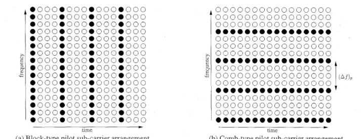
Based on the principle of OFDM transmission scheme, it is easy to assign the pilot both in time-domain and in frequency- domain. Several types of pilot arrangement have been studied [I]. Here we consider two major types of pilot arrangement as shown in Fig. 2 . The first kind of pilot arrangement shown in Fig. 2(a) is denoted as block-type pilot arrangement. The pilot signal is assigned to a particular OFDM block, which is sent periodically in time-domain. This type of pilot arrangement is especially suitable for slow-fading radio channels. Because
Hsieh and Wei: Channel Estimation for OFDM Systems Based on Comb-llpe Pilot Arrangement in Frequency Selective Fading Channels
_c
--t
Signals
-
aherFFT-
the training block contains all pilots, channel interpolation in frequency domain is not required. Therefore, this type of pi- lot arrangement is relatively insensitive to frequency selectivity. The estimation of channel response is usually obtained by LS or MMSE estimate of training pilots [ 5 ] [6].
The second kind of pilot arrangement shown in Fig. 2(b) is de- noted as comb-type pilot arrangement. The pilot signals are uni- formly distributed within each OFDM block. Assuming that the payloads of pilot signals of the two arrangements are the same, the comb-type pilot assignment has a higher re-transmission rate. Thus, the comb-type pilot arrangement system is provides better resistance to fast-fading channels. Since only some sub- carriers contain the pilot signal, the channel response of non- pilot subcarriers will be estimated by interpolating neighboring pilot sub-channels [ 2 ] [3]. Thus, the comb-type pilot arrange- ment is sensitive to frequency selectivity when comparing to the block-type pilot arrangement system. That is, the pilot spacing (Af), must be much smaller than the coherence bandwidth of the channel ( A f ) c.
In this paper, we consider the radio channel which changes rapidly. In such environment, the channel transfer function changes significantly from one block to the next block. Thus, the channel estimation in the present block can not be used as the channel response of the next bIock. Therefore, the comb-type pilot subcarrier arrangement is adopted to estimate the channel transfer function in each block. As shown in Fig. 3, the pilot signals is first extracted from the received signal, and the chan- nel transfer function is estimated from the received pilot signals and the known pilot signals. Then, the channel responses of subcarriers that carry data are interpolated by using the neigh- boring pilot channel responses. In the following sections, the pilot signal estimation and channel interpolation algorithms are discussed separately.
-r Channel
Response
---t
Extraction
-
Received Pilot Signal Pilot Signal
t-1
ChannelE
Estimated111. PILOT S I G N A L E S T I M A T I O N
For comb-type pilot subcarrier arrangement, the
N p
pilot sig- nals X p ( m ) , m = 0,1, . . .,
N p - 1 are uniformly inserted intoX ( k ) . That is, the total
N
subcarriers are divided into N p groups, each withL
= N / N p adjacent subcarriers. In each group, the first subcarrier is used to transmit pilot signal. The OFDM signal modulated on the kth subcarrier can be expressed as X ( k ) = X ( m L f 1 ) (8) 1= o ,
information data, 1 = 1 , 2 , .. . ,
L
- 1. 219The pilot signals { X P ( m ) } can be either equal complex values
c to reduce the computational complexity, or random generated data that can also be used for synchronization.
Let
H, = W P ( 0 ) HP(1) " %(NP -
IllT
=
[H(O)
H ( L - 1). . .
H ( ( N , - 1 ) . L - l)]' (9)y , =
CYP(0)
YXNP - 111' (10)be the channel response of pilot subcarriers, and
be the vector of received pilot signals. The received pilot signal vector Y, can be expressed as
Yp
=X, . H p
+ I p + W p , X P ( 0 ) 0 (1 1) wherex,
=[
0 X,(NP - 1)I, is the vector of IC1 and W, is the vector o f Gaussian noise in pilot subcarriers.
In conventional comb-type pilot based channel estimation methods, the estimate of pilot signals, based on least squares (LS) criterion, is given by:
% , l S = [ H P , l S ( O ) l7,,ls(1) '
. .
H P , l S ( N P - 1)IT=
xply,
The LS estimate of Hp is susceptible to Gaussian noise and inter-carrier interference (ICI). Because the channel responses of data subcarriers are obtained by interpolating the channel re- sponses of pilot subcarriers, the performance of OFDM system based on comb-type pilot arrangement is highly dependent on the rigorousness of estimate of pilot signals. Thus a estimate better than the LS estimate is required.
The minimum mean-square error (MMSE) estimate has been shown to be better than the LS estimate for channel estimation in OFDM systems based on block-type pilot arrangement [ 5 ] . Regarding the mean square error of the estimation shown in [ 5 ] , the MMSE estimate has about 10-15 dB gain in SNR over the LS estimate for the same MSE values. The major drawback of the MMSE estimate is its high complexity, which grows ex- ponentially with the observation samples. In [6], a low-rank approximation is applied to a linear minimum mean-squared er- ror (LMMSE) estimator that uses the frequency correlation of the channel. In this paper, the same facilitating process is ap- plied to estimate the comb-type pilot signals. The key idea to reduce the complexity is using the singular-value decomposi- tion (SVD) to derive an optimal low-rank estimator, where per- formance is essentially preserved. The mathematical represen- tation for MMSE estimator of pilot signals is as follows [6]:
220 lEEE Transactions on Consumer Electronics, Vol. 44, No. 1, FEBRUARY 1998 ji *
;
c?-
g
00
0
0
00
0 0 0 00
0 0 0 00
.000.000.000.000.000.000.000.000
.000.000.000.000 .000.000.000.000 0000.000.000.000 .000.000.000.000 .000.000.000.000.000.000.000.000
.000.000.000.000
.000.000.000.000
.000.000.000.000.000.000.000.000
.000.000.000.000
.000.000.000.000
.000.000.000.000 *2-
2
Fig. 2. Two different types of pilot sub-carrier arrangement
0000000000000000 0000000000000000
...
0000000000000000 0000000000000000 00000000000000000000000000000000
0000000000000000
...
0000000000000000
0000000000000000
0000000000000000
...
...
t
0000000000000000
(Ai),where HP,ls is the least-squares estimate of HI, as shown in (12), g i is the variance of W ( k ) , and the covariance matrices
are defined by
RH,H, = E{H,HE},
RH,H,,~, = E { ~ p ~ p " , l ~ >
R H , , ~ ~ H , , ~ ~ =
E
{HmHF,lS} .Note that there is a matrix inverse involved in the MMSE es- timator, which must be calculated every time. This problem can be solved by using static pilots such as X,(?n) = c for
m
= 0, 1, . .,
N, - 1. A more generic solution is to average over the transmitted data, and a simplified linear MMSE estima- tor of' pilot signals is obtained as [6]:-1 H P , l S >
where SNR = E ( X , ( k )
1'
/ D : is the average signal-to-noise ra-tio, and
p
= E i X p ( k ) i 2E
11/Xp(k)12 1s a constant depend- ing on the signal constellation For 16-QAM transmission,p
= 17/9 If the auto-correlation matrixR H , H ~
and SNR are known in advance,RH,H, (RH,H,
+
&I)
needs to be calculated only once Although the simplified LMMSE estima tor avoids the matrix inverse operahon, the computational com plexity is still very high As shown in (14), the estimation re- quires N, complex multiplications per pilot tone To reduce the number of multiplication opeiations, a low-rank appioximation using singular value decomposition IS adopted [6] The channelcorrelation matrix is first decomposed as
-1
RH,H, = U h U H (15)
where U IS a matrix with orthonormal columns U O , u1, , U N , - ~ and A is a diagonal matrix, containing the singular val-
ues X(0)
<
X(1)<
5
X(Np
- 1)5
0 on its diagonalThe best rank-m approximation of the estimator in (14) then be- comes
H, = U
[
4;..
;
]
UHHp,ls,where A, is a diagonal matrix containing the values
.
k = O , l , . . . . m (17)X(k)
X(k)
+
SNR
S(k)
=After some facilitations, the estimator in (16) thus requires
2mNp multiplications and the total number of multiplications per pilot tone becomes 2m. In general, the number of signifi- cant singular value 772 is much smaller than N,, and the com-
putational complexity is reduced considerably comparing to the full rank estimator (14).
The low-rank MMSE estimator is insensitive to parameter mismatch [6]. That is, it is possible to design a generic rank- m estimator for a wide range of channels.
IV. CHANNEL INTERPOLATION
After the estimation of the channel transfer functions of pilot tones, the channel responses o f data tones can be interpolated according to adjacent pilot tones. The piecewise-linear interpo- lation method has been studied in [ 2 ] , and is shown to be better .than the piecewise-constant interpolation. In this paper, we con-
sider a piecewise-linear and a piecewise second-order polyno- mial interpolation method which due to their inherent simplicity are easy to implement.
A. Linear interpolarion method
In the linear interpolation algorithm, two successive pilot sub- carriers are used to determine the channel response for data sub- carriers that are located in between the pilots [ 2 ] . For data sub- carrier k , mL
<
k<
( m+
l)L, the estimated channel response using linear interpolation method is given byI 7,
H ( k ) =
H ( m L
+
I )
=L
1 - -e)
Ei,(m)+
L Q m
L
+
1)The linear channel interpolation can be implemented by using digital filtering such as the Farrow-structure [ 81. Furthermore,
Hsieh and Wei: Channel Estimation for OFDM Systems Based on
Comb-Type Pilot Arrangement in Frequency Selective Fading Channels 22 1
by carefully inspecting (18), we find that if L is chosen as the power of 2, the multiplication operations involved in (18) can be replaced by shift operations, and therefore no multiplication operation is needed in the linear channel interpolation.
B. Second-order polynomial interpolation method
Theoretically, using higher-order polynomial interpolation will fit the channel response better than the linear interpolation. However, the computational complexity grows as the order is in- creased. Here
we
consider the second-order polynomial interpo- lation for its acceptable computational complexity. A piecewise second-order polynomial interpolation can be implemented as a linear time-invariant FIR filter [9]. The interpolator is given bywhere a(oi+1) 2
cl)
= - ( C Y - l)(CY+l)c-l
= 4 a - 1 ){”’
= 2 and CY = l / N .C. Phase compensated interpolation
For a realistic OFDM system, the frame position error will affect the channel estimation. Because of the low-pass filtering in the receiver, the sampled channel impulse is dispersed and introduces energy leaks, especially, when the path delay time is non-T-spaced [ 5 ] . Due to the multipath propagation and the en- ergy leaks due to sampling, the guard interval will be affected by the preceding symbol. To avoid the inter-symbol interference, the frame synchronization must provide a portion
{ g ( n ) }
of the samples {yg(n)} of length N that is influenced by one transmit- ted symbol only. Let the correct position of the FFT window isp = q(N,
+
N ) where q isa
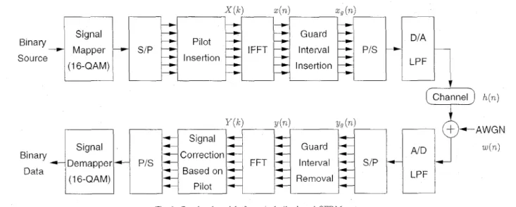
positive integer and p E the offset with respect to this position. In [lo], a frame misalignment is identified as two situations as shown in Fig. 4.Suppose that the start position of the FFT window is within region A, then no IS1 occurs. The only effect suffered by the subchannel symbols is a change in phase that increases with the subcarrier index.
If
the start position is within regions B, the subcarrier symbols will suffer from IS1 in addition to the phase rotation, and the orthogonality of the system is disturbed. In this paper, we assume that the coarse frame synchronization has pulled the frame start position p , within region A. Thus the re- ceived signal after FFT becomes [ 101Y ( k ) = X ( k ) H ‘ ( k )
+
W ’ ( k )=
x
( k ) j y ( /+--324Pe - l V g ) / N+W(j+-”2”(P‘-Ns)IN. (20)
From Fig. 4, we see that p E
5
N g when p , is in region A. Therefore, a group delay exists at the OFDM receiver before de- multiplexing. The group delay in time-domain introduces phase rotations after demultiplexing, which introduce model mismatchAT, IV channel impulse -+ response
\
I B ~ A /
I B 14’
I I I*;
P , { Y ( / c l } FFT WindowFig. 4. Principle of frame synchronization [lo]
Fig. 5. The influence of frame position error to interpolations.
error for channel interpolation algorithms. As shown in Fig. 5 , the linear interpolation algorithm introduces significant errors when the group delay is present. In addition, the model mis- match error grows as the group time delay increases. The model mismatch problem is more serious for the comb-type pilot sys- tem than the block-type pilot system, since the comb-type pi- lot system uses interpolation to determine the channel response of the data carriers, and the pilot carriers are separated more widely. In addition, the MMSE estimator discussed in Sec- tion I11 is sensitive to the timing error. The reason is that the MMSE estimator uses a pre-estimated channel statistics to esti- mate the pilot signals. If the frame position error is present, the
MMSE
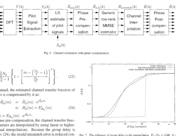
estimator will fail due to mismatch of channel statistics. Here we propose a method to solve the model mismatch prob- lem as shown in Fig. 6. The estimated channel transfer function of pilot signals when a group delay in time domain is present can be represented by(21)
where 6, is the change in phase caused by frame error and E H ~ ( m ) is the estimation error. We can see that {fi,(m)} is a sequence that with a single frequency. Therefore, the estimators presented in [ 111 can be applied to estimate O P . The estimator in [ 111 that provides the best overall performance is
Gp(nz)
= H , ( m ) . e-i*P”+
E f f p ( m ) ,N p - 2
e,
=w,Lfi;(m)H,(m
+
1) (22)222 IEEE Transactions on Consumer Electronics, Vol. 44, No. 1, FEBRUARY 1998 0 1 q Y Q 0.01 Z l a r s e E I
-
-
DFT
Pilot1
estimateLs
frame Signal --)- of pilot-
sync. Extraction-
signals . . . ... ;-. /-..- ~ -.- - ,_-I , , ,,’ ,I’ : ~ ,._- __.j ... H p , k ( k ) H p , l s ( q f 4 L l m m s e ( k )fi(W
low-rank Inter- MMSE compen- polation estimator sationFig 6 Channel estimation with phase compensation
where
After
4,
is obtained, the estimated channel transfer function of pilot subcarriers is compensated by itas:
Hp(m)
= I Z , ( m ) . e j Q p mM H,(m)
+
EL,
( m ) (24)where ELp ( m ) = E H ~ ( m ) . e j o p m .
After the phase pre-compensation, the channel transfer func- tions of data carriers are interpolated by using linear or higher- order polynomial interpolations. Because the group delay is compensated by (24), the model mismatch error is reduced con- siderably. Then, after interpolation, the phase change is restored as :
Fig. 7 shows the influence of frame position error on the chan- nel estimation. The FFT size N = 1024, total number of pilot subcarriers
N,
is 128, and Eb/No equals 10 dB. The AWGN channel is adopted, with the delay time h o m 0 to 100 samples. From Fig. 7, we can see that interpolations without phase com- pensation will suffer from frame position error, even there is no ISI. The phase compensator is not affected by frame position er- ror for 8,<
rr. When QP is larger than r (corresponding to the 64th sample shown in Fig. 7), the phase estimator suffers from phase ambiguity and therefore the compensator failed. How- ever, since the phase change 0, is more probable to be positive, the applicable range of theAphase compensator can be enlarged by changing the range of 8, from [ - T , T ) to [-T -k4 , ~
+
4)
From Fig. 7, we can see that the performances of linear and polynomial interpolations are not sensitive to frame position er- rors when the frame offset is small. This enlight us to use a simpler estimator of phase change instead of (22). We choose a simpler estimator from [l 11 and the phase estimator iswhere 0
5 & 5
71.-
N p - 2 1e,
=-
1
fi;(m)fiP(7rL i- 1) m=O N - 1According to our own simulations, the performances of channel estimator applying the phase compensators shown in (22) and (26) are almost the same.
Linear intbrpo~ation -
2nd-order polynomial interpolation ...
Linear interpolation with phase compensation . .
0001 I I
0 20 40 60 80
.
100 Delag ( s a m p l e s )Fig 7 The influence of gioup delay to the interpolation Eb/No = 10dB, N = 1024, N p = 128
V.
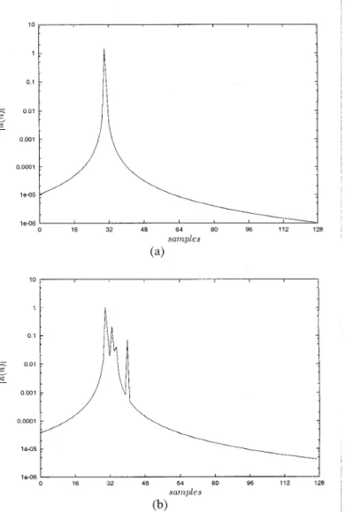
SIMULATIONSThe proposed channel estimation method is evaluated under slow- and fast-fading radio channels. As in [ 3 ] , the same simula- tion environments are used in this paper. An OFDM system with symbols modulated by 16-QAM is used. The carrier frequency is 1 GHz, and the bandwidth is 2
MHz.
The total number of sub- channels isN
= 1024, and the number of uniformly-distributed pilot carriers is N p = 128. The channel models adopted are Rayleigh and Rician as recommended by GSM Recommenda- tions 05.05 [12], with parameter shown in TABLE I. Here we assume that the guard intervals are longer than the maximum delay spread of the channel. To avoid IS1 arising from energy leakages caused by sampling, a frame position offset of 30 sam- ples is applied. The sampled channel impulse response in time- domain is shown in Fig. 8. We can see that there are energy leakages ahead the main path sample.Several channel estimation methods, LS estimate of pilot with linear interpolation, MMSE estimate of pilot with linear inter- polation, MMSE estimate of pilot with 2nd-order polynomial interpolation, MMSE estimate of pilot with phase compensated interpolations, and channel estimation using transform domain proce,ssing technique, are simulated and compared. The sim- ulations are carried out for different noise and IC1 levels, and the. results are shown in Fig. 9-12. The horizontal variable is chosen as the signal energy per bit-to-noise power density ratio (Eb,”,-,). The IC1 levels are controlled by the vehicle speed.
Hsieh and Wei: Channel Estimation for OFDM Systems Based on Comb-Type Pilot Arrangement in Frequency Selective Fading Channels
Path Number
1
223
-
Rayleigh Channel Rician Channel
Average, Average.
Power Delay (ps) Power Delay (ps) dB -3.0 0.0 0.0 0.0 (dB) 2 3 4 0.0 0.2 -4.0 0.1 -2.0 0.5 -8.0 0.2 -6.0 1.6 -12.0 0.3 5 6
For low vehicle speed V = 6 k d h r , the corresponding max- imum Doppler spread is 0.3 % of the subcarrier spacing. Thus, the IC1 can be neglected. For high vehicle speed V = 150 k d h r , the corresponding maximum Doppler spread is then 7.5
% of the subcarrier spacing. Thus, the system performances are strongly affected by ICI. After decomposition of the auto- correlation matrices of Rayleigh and Rician channels, we find the sufficient rank of MMSE estimators are are 6 and 4, respec- tively. However, when we use the rank-6 estimator designed for Rayleigh fading channel as the pilot signal estimator of Ri- cian fading channel, the performance degradation is neglectable. Thus, a generic low-rank estimator can be used for slow- and fast-fading Rayleigh and Rician fading channels.
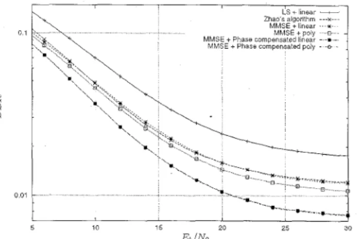
From Figs. 9-12, we see that the performance is improved significantly when the low-rank MMSE estimator is applied. The phase compensated interpolation successfully solves the model mismatch problem, and gains a significant improvement in Eb/No for the same BER values in all cases. We also notice that the higher-order polynomial interpolation only improves the performance little. It is suspectable to use higher-order poly- nomial interpolation instead of linear interpolation for channel with small delay spread. However, we expect that the improve- ment in performance will be more if the delay spread of channel is larger. The performance of Zhao and Huang's algorithm is limited by the low-pass filtering in transform domain. In higher SNR, the low-pass filtering operation discards some channel in- formation and thus a BER floor is formed.
From the simulations shown above, we see for comb-type pi- lot assisted OFDM systems, the channel estimation based low- rank MMSE pilot estimator with phase compensated linear in- terpolation is suggested. The proposed method eliminate IC1 and AWGN by using the low-rank MMSE pilot estimation, and the model mismatch error is reduced by using linear interpola- tion with phase compensation. It should be note that although the proposed algorithm provided better performance, the SNR and channel statistics have to be estimated in advance. Whereas the channel estimation based on transform domain processing needs not to know these informations in advance.
J
-8.0 2.3 -16.8 0.4
-10.0 5.0 -20.0
I
0.5VI. COMPUTATIONAL COMPLEXITY
In this section, we compare the computational complexity of the proposed algorithm and the channel estimation algorithm
' "
t
i
I 0 16 32 48 64 80 96 112 128 le-06 snnrples (b)Fig. 8. Typical channel impulse of (a) Rician and (b) Rayleigh fading channels.
presented in [ 3 ] . We evaluate the computational complexity roughly by calculate the number of complex multiplications used per tone to estimate the channel transfer function. The pro- posed method uses low-rank MMSE estimator, which requires
2 m N p complex multiplications where m is the rank of the es- timator. The phase estimator requires N p complex multiplica- tions, and the phase compensator requires N complex multi- plications. As shown in (1 8), the linear interpolation requires no multiplications. Thus, the proposed method totally requires 2mNp
+
N p+
N complex multiplications, which is equivalent to 1+
complex multiplications per tone. The chan- nel estimator based on transform domain processing uses two FFTs to estimate the channel response, one is of size N p and the other is of size N . By using the decimation-in-frequency radix-4 implementation of FFT, the total number complex mul- tiplications required is roughly N p log, N p+
Nlog, N . Note that about one or two multiplications can be savedfor
FFT be- cause of some trivial multiplications. By using the parameters in Section V, the proposed channel estimator only requires about 2 complex multiplications per tone, while the channel estima- tor proposed by 131 requires at least 4-5 complex multiplica- tions per tone by conservative estimate. Therefore, the proposed channel estimator is computational efficient and is attractive for224 IEEE Transactions on Consumer Electronics, Vol. 44, No. 1, FEBRUARY 1998
0 1
0.01
0.001
Fig. 9. Comparisons of BERs in slow Rayleigh fading channel (vehicle speed = 6 k d h r ) . 0 1
w
2
MMSE +linear MMSE + poly MMSE + Phase compensated linearMMSE + Phase compensated poly
O o l
5Y
10 15 20 25 30&/No
Fig. 10. Comparisons of BERs in fast Rayleigh fading channel (vehicle speed
= 150 kmkr). a; Y Q 0 1 0 01 0 001
Fig 11 Compansons of BERs in slow Rician fading channel (vehicle speed = 6 k d h r ) 0 1
w
N Q 0 01 5 10 i s 20 25 30 &/NoFig. 12. Comparisons of BERs in fast Rician fading channel (vehicle speed =
150 kmihr).
OFDM systems in mobile communications VII. CONCLUSION
In this paper, a low-complexity channel estimator based on comb-type pilot arrangement is presented. The channel transfer function of pilot tones are estimated by using low-rank MMSE estimator, and the channel transfer function of data tones are in- terpolated by piecewise linear interpolation method with phase compensation. Simulations show that the performance of the proposed channel estimator outperforms the channel estimator based on transform domain processing presented by Zhao and Huang [ 3 ] . The computational complexity of the proposed chan- nel estimator is also studied, and is lower than the previous chan- nel estimator in [ 3 ] . In conclusion, the proposed channel estima- tor provides a practical channel estimation for OFDM systems based on comb-type pilot arrangement.
ACKNOWLEDGMENT
This work was supported by the National Science Council of Republic of China under contract NSC 86-2221-E-009-053.
REFERENCES
[ I ] E Tufvesson and T Maseng, “Pilot assisted channel estimation for OFDM in mobile cellula- systems,” in P roc. IEEE 47th Vehicular Technology Con- ference, Phoenix, USA, May 1997, pp. 1639-1643
J. Rinne and M. Renfors, “Pilot spacing in orthogonal frequency division multiplexing systems on practical channels,” IEEE Trans. Consumer Elec-
tronics, vol. 42, no. 4, Nov. 1996.
Y. Zhao and A. Huang, “A novel channel estimation method for OFDM mobile communication systems based on pilot signals and transform- domain processing,” in P ~ o c . IEEE 47th Vehicular Technology Conference,
Phoenix, USA, May 1997, pp. 2089-2093.
R. Steele, Mobile Radio Communications, London, England, Pentech
Press Limited, 1992.
J.-J. van de Beek, 0. Edfors, M. Sandell, S. K. Wilson and P. 0 . Borjesson, “On channel estimation in OFDM systems,” in P roc. IEEE 45th Vehicular
Technology Conference, Chicago, IL, USA, Jul. 1995, pp. 815-819. 0. Edfors, M. Sandell, J.-J. van de Beek, S. K. Wilson and P. 0 . Borjesson, “OFDM channel estimation by singular value decomposition,” in Proc. IEEE 46th Vehicular Technology Conference, Atlanta, GA, USA, Apr. 1996, pp. 923-927
V. Mignone and A. Morello, “CD3-OFDM: a novel demodulation scheme for fixed and mobile receivers,” IEEE Trans. Comm., vol. 44, pp. 1144-
1151, Sep. 1996. [2] [3] [4] [5] [6] [7]
Hsieh and Wei: Channel Estimation for OFDM Systems Based on
Comb-Type Pilot Arrangement in Frequency Selective Fading Channels
(81 C. W. Farrow, “A continuously variable digital delay element,” in Proc. IEEE Int. Symp. Circuifs & Sysf., Espoo, Finland, pp. 2641-2645, June
6-9, 1988.
G . 4 . Liu and C.-H. Wei, “A new variable fractional sample delay filter with nonlinear interpolation,” IEEE Trans. Circuits and Systems-11: Anu- log andDigiral Signal Processing, vol. 39, no. 2, Feb. 1992.
[lo] M. Speth, E Classen and H. Meyr, “Frame synchronization of OFDM sys- tems in frequency selective fading channels,” in Proc. IEEE 47th Vehicular Technology Conference, Phoenix, USA, May 1997, pp. 1807-181 I .
[ll] S. Kay, “A fast and accurate single frequency estimator,” IEEE Trclns. Acoustic, Speech, and Signal Proc., vol. 37, no. 12, Dec. 1989.
[12] European Telecommunications Standards Institute, European Digital Cel- lular Telecommunication System (Phase 2): Radio Transmissi~in una’ Reception, GSM 05.05, vers. 4.6.0, Sophia Antipolis Cedex, France,
Jul. 1993.
[13] W. C. Jake, Microwave mobile communications, New York, Wiley, 1974.
[9]
BIOGRAPHY
Meng-Han Hsieh (S’96) was born in Taiwan, R.O.C., in 1968. He received the B.S. and M.S. degrees in electronics engineering form National Chiao Tung University, R.O.C., in 1990 and 1992, respectively.
He is currently working toward the Ph.D. de- gree at the same school. His research interests include multi-camer signal processing, synchro- nization and channel estimation algorithms.
Che-Ho Wei (S’73-M’76-SM’S7-F196) was born in Taiwan, R.O.C., in 1946. He received his B.S. and M.S. degrees in electronics engineering from the National Chiao Tung University, Hsin Chu, Taiwan, in 1968 and 1970, respectively, and his Ph.D degree in electrical engineering from the University of Washington, Seattle, in 1976.
From 1976 to 1979, he was an associate pro- fessor at the National Chiao Tung University, where he is now a Professor with the Department of Electronics Engineering and Dean of College of Electrical Engineering and Computer Science. From 1979 to 1982, he was the engineering man- ager of Wang Industrial Company in Taipei. He was the Chairman of the Department of Electronics Engineering of NCTU from 1982 to 1986, and Director of Institute of Electronics from 1984 to 1989. He was on leave at the Ministry of Education and served as the Director of the Advisory Office from September 1990 to July 1992. His research interests include digital communications and signal processing, and related VLSI circuits design.
![Fig. 4. Principle of frame synchronization [lo]](https://thumb-ap.123doks.com/thumbv2/9libinfo/7517332.118326/5.934.469.837.85.582/fig-principle-frame-synchronization-lo.webp)