4 CELMA, s., S A H A D E L L , .I, and MARTINEZ, P : 'Universal filter using unity-gain cells', Electron. Lett., 1995, 31, pp. 1817-1818
5 B R U U N . E.: 'Constant-bandwidth current mode operational amplifier', Electron. Lett., 1991, 21, pp. 1673-1674
Insensitive current/voItage-mode filters
using
FTFNs
Shen-Iuan Liu and Jiin-Long Lee
Indexing terms: Current-mode circuits, Active filters, Analogue circuits
It can simultaneously realise a bandpass filter and a lowpass filter. The natural frequency and quality factor of this filter can be expressed as
taking into account the nonideal FTFN, i.e. V, = aV, and ZtI2 = PZo, where a = 1-&I and E, (q << 1) denotes the voltage tracking error of an FTFN; and
P
= 1-E~ and (E, << 1) is the current tracking error. Sirice the current output of the FTFN2 in Fig. 2 is directly connected to the load (R?), the resultant current-mode fil- ters will be insensitive to the current tracking error of the FTFN2 except for current gain. The transfer function ZOl/Jn in Fig. 2 can be rewritten as(4)
Id
- C L ~ J S C ~ R ,--
-I,, alu.2/3,
+
sClR1+
s2CICzRlR2 A new configuration for realising insensitive current/ voltage-mode fillers using two four-terminal floating nullors (FTFNs) is presented, It can provide the CurrenVvoltage-mode filters with reduced sensitivities. Moreover, the current-mode filters can have
proposed universal voltage-mode filter with dual outputs can C I C? - R I R3 - -0.5
realise lowpass, bandpass, highpass, notch and allpass filtering functions. Simulation results are given to verify the theoretical analysis.
it can be found that the passive and active sensitivities of this filter are
high output impedance and only grounded capacitors. The
s""
S"', - S W < > =S"<'
- S'
cz =
-Sz,
I=-Sj,
= Sz2 = 0.5s"..
~ = -Sd<j SQ = ~ 6 2 ~ =-sQ
0.50 1 a2 31 C Y 1 81
Introduction: Current-mode circuits have been receiving significant attention besause they have the potential advantages of accuracy and wide bandwidth over their voltage-mode counterparts [I]. To be cascaded without additional current buffers, it is desirable for current-mode filters to have high output impedance. Therefore, several cascadable current-mode filters [2 - 61 using second gener- ation current conveyors (CCIIs) and single four terminal floating nullor (FTFN) [7, 81 have been developed. Recently, a cascadabk current-mode filter [6] using single F T F N was presented. How- ever, its active sensitivities were large and it requires a floating capacitor. In this Letter, a new configuration is presented to pro- vide the currentivoltage-mode filters with reduced sensitivities. Simulation results are given to verify the theoretical analysis.
f1:O
193111j
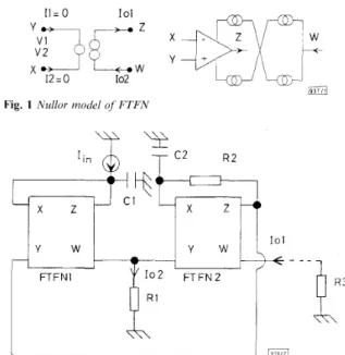
Fig. 1 Nullor model of FTFN
S";
= SQ -3: 0 2 - 0
Thus, the passive arid active sensitivities of this filter are all low. Moreover, this filter can provide a high impedance output and it contains only grounlded capacitors.
Vir12 Vin 3 0 R2 Cl
1
T
c2 I I I R I I I Ij r n
Fig. 3 Voltuge-mode universal filterThe proposed voltage-mode universal filter is shown in Fig. 3. Its transfer function can be expressed as
s2C1C2RlRZl/;n3
+
, S C ~ R ~ K / , , ~+
V,l = ~ (5) (6) 1+
s C ~RI
+
s ' C ~C,
RI
R,
x zVOl
= SC2R3(VO1 - V i 7 % 3 )If
U;,,,
=vn3
= 0, a lowpass function and a bandpass function can be obtained atvj,
andE,,
respectively. ifvnl
=vn3
= 0, a band- pass function and a highpass function can be achieved atvJ,
andvj2,
respectively. Moreover, ifViri2
= 0 andyr,,=
I&,
a notch func-tion and a bandpass function can be obtained at
y,l
andVI,.
To realise the allpass filter, input signals must have the following rela- tions:vrz1
=-v,hZ
=y,,,.
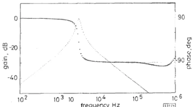
Its natural frequency and quality factor are given in eqn. 3. Its passive and active sensitivities are also low. Sinzulation results: To verify the theoretical analysis. the proposed currentivoltage-mode filters have been simulated, based on the advanced PSPICE rnacromodels [9]. The FTFN [8] consists of the AD704 [lo] Op Amp, Q2N2222A NI" and Q2N2907A PNP transistors. As an example, the simulation results of the proposed current-mode bandpass filter in Fig. 2 were presented with Cl = C, = lOnF, RI = lkQ, and R, = R, = 25kQ. Fig. 3 shows the simula- tion results of the second order bandpass filter. Simulation results conform with the results of the theoretical analysis. Other pro- PSPICE macromodels.Y W
FTFNI
pGJ
Fig. 2 Proposed current-mode ,fi'ltev with high output irnpedmce
Circuit description: An F T F N is equivalent to an ideal nullor [6 - 81. The port relations of an FTFN, shown in Fig. 1, can be char- acterised as I , = I, = 0,
V,
= V, and Zol = I,>>. Considering the pro- posed current-mode configuration in Fig. 2, its transfer functions can be derived as- posed filters have also been verified as working properly by
ELECTRONICS LETTERS 6th June 1996 Vol. 32 No. 12 1079
(1)
I o 1 sC:,
RI
I,,
-
102 1 0 3 10 104 IO 5 10 6 frequency,Hz
Fig. 4 Comparisons between theoretical and simulated results .for bund- pass filter in Fig. 2 with C, = C, = IOnF, R, = I k a and R, = R, = 2 5 1 ~ 0
Theoretical: -- gain, - - - phase
Simulated: ~~~~~. gain, +++ phase
Conclusions: The proposed circuits have been thoroughly verified by using the PSPICE macromodel simulations. This configuration can provide the currentholtage-mode filters with reduced sensitiv- ities. Moreover, the current-mode bandpass can have high output impedance and only grounded capacitors. The voltage-mode filter can be a universal filter. The proposed circuits are expected to be useful in analogue filtering applications.
0 IEE 1996
Electronics Letters Online No: 19960729
Shen-Iuan Liu and Jiin-Long Lee (Department of Electrical Engineering, National Taiwan University, Taipei, Taiiran 10664,
Republic of China)
16 A p d I996
References
1 WILSON, B : 'Recent developments in current conveyors and current- mode circuits', IEE Pioc. G, Circuits Devices Syst., 1990, 137. (2),
pp. 63-11
2 L i u , s.1 , TSAO, H w., and w u , J . : 'Cascadable current-mode single CCII biquads', Electron. Lett., 1990, 26, pp. 2005-2006
3 CHANG, c M.: 'Current-mode allpasshotch and bandpass filter using single CCII', Electron. Lett., 1991, 27, pp. 1812-1813
4 NANDI, R.: 'Novel current-mode all-pass phase shifter using a current conveyor', ZEEE Trans. Instrun?. Meas., 1992, IM-41. pp. 553-555
5 HIGASHTMURA, M.: 'Realisation of current-mode transfer function using four-terminal floating nullor', Electron. Lett., 199 1, 27. pp.
170-171
6 LIU, s I.: 'Cascadable current-mode filters using single FTFN'.
Electvon. Lett., 1995, 31, pp. 1965-1966
7 H u I J s i N G . J H.: 'Operational floating amplifier', IEE Proc. G,
Circuits Devices Syst., 1990, 137, pp. 131-136
8 SENANI, K.: 'On equivalent forms of single op-amp sinusoidal RC oscillators', IEEE Trans. Circuits Syst. I, Fundum. Theory Appl.,
MicroSim Corp., Irvine, California, 1993 1994, CAS-41, pp. 617-624
9
10 Analog Devices, Norwood MA, 1990
Linearly constrained block adaptive filtering
algorithm with optimum convergence
factors
T. Demeechai
Indexing terms: Adaptive jilters, Array signal processing
A new linearly constrained adaptive filtering algorithm, the linearly constrained optimum block adaptive (LCOBA) algorithm, is presented. The LCOBA algorithm processes data in blocks and uses variable convergence factors which are optimised in a least squares sense. It is superior to Frost's linearly constrained least mean square algorithm at achieving the conflicting goals of fast convergence with little steady-state error. In addition, its computational requirement generally tends to be smaller than that of the Frost algorithm, as the block length is increased.
Introduction: Linearly constrained adaptive filtering is an impor- tant tool in array processing problems. The most widely used algo- rithm. owing to its simplicity, efficiency and robustness, is the linearly constrained least mean square algorithm proposed by Frost [l]. The convergence properties of the Frost algorithm criti- cally depend on a fixed parameter known as the convergence fac- tor. A relatively large convergence factor may result in fast convergence but large steady-state error. The proper value of the convergence factor must be selected to balance the conflicting goals of fast convergence and small steady-state error. This usually requires prior information about the adaptive filter input process, as well as trial and error.
This Letter presents a new block gradient algorithm for linearly constrained adaptive filtering which uses convergence factors opti- mised in a least squares sense for each update of the filter weight vector: the linearly constrained optimum block adaptive (LCOBA) algorithm. The expression for the optimum convergence factors is derived simply, and in a similar way to that in [2]. In the LCOBA algorithm, the blocks of processed signals are disjointed: therefore, the computational requirement of the new algorithm tends gener- ally to be smaller than that of the Frost algorithm, as the block length is increased. Computer simulations are also conducted for evaluating the convergence properties of the LCOBA algorithm. The results show that the new algorithm is superior to the Frost algorithm at achieving the conflicting goals of fast convergence with little steady-state error.
T h e LCOBA algorithm: A linearly constrained adaptive filter may be considered as an FIR filter with an adaptive process, for mini- mising the output mean square error, that recursively adjusts the filter weight vector W which is constrained by an equation such as: CHW = F: where the superscript (.)" denotes complex conju- gate and transpose. The weight vector has dimensions N x 1, where N is the number of filter taps. The constraint matrix C has dimensions N x K, where K is the number of constraints. The idea behind the LCOBA algorithm is similar to that b e h d the Frost algorithm, since the LCOBA algorithm uses a negative gradient, orthogonalised to all of the constraint matrix column vectors, multiplied by a convergence factor and then added with a correc- tion term for each recursion. However, the LCOBA algorithm works with disjointed blocks of data and uses variable conver- gence factors o p t i s e d in a least squares sense. In LCOBA algo- rithms with block length L, the error signal matrix for each data block is defined by
where the subscript D and X are, respectively, the block index, the 1 x L desired signal matrix and the N x L input signal matrix. It can be shown that half the negative gradient for thejth block sum square error
E,E,H
equals Therefore, after being initialised by WO = C(CHC)-'F, the LCOBA algorithm is based on the recur- sionE3 = D, - W Y X , (1)
T@>+1 : LV,
+
p , ( I - C(CHC)-'CH)X,E,"+
C ( C H C ) - ' ( F - CHW,) (2) where I is the identity matrix and p, is a real number representing the optimum convergence factor for j t b recursion. This conver- gence factor is optimal in the sense that it minimises the a posteri- ori block sum square errorC,iH,
whereOwing to the fact that
<,E,,"
is a quadratic function of the filter weight vector, it can be shown (from eqns. 2 and 3) thatk,k,"
may be expressed by a parabolic function of the convergence factor, and the optimum convergence factor isE,
= D, - W,",J, ( 3 )Computer simulations: To illustrate the performance of the LCOBA algorithm, computer simulations on minimum variance filtering similar to those in [3] have been conducted. The perform- ance measure is the normalised error energy (NEE) defined by