I
High-speed Reed-Solomon decoder for correcting
errors and erasures
C.-H. Wei, PhD C.-C. Chen, MSc G.-S. Liu, MSc
Indexing terms : Error-correction coding, Reed-Solomon decoder
Abstract: A Reed-Solomon decoder for errors- and-erasures correction, based on a new algebraic decoding algorithm, is presented. This high-speed decoder requires only n clock cycles for decoding each received n-symbol block. A serial structure that requires very few multipliers and provides a general expression to calculate the coefficients of the erasure-locator polynomial is also presented. A (15, 11) RS decoder and its shortened version (7, 3) RS decoder are used as design examples to illustrate the operating procedure of the new decoding algorithm.
1 Introduction
The encoder/decoder for an RS code differs from a binary encoder/decoder in that it operates on multiple bits instead of individual bits [l-4). An (n, k) RS code is a block sequence of symbols in a Galois field GF(2"'). This sequence of symbols can be considered as the coefficients of a code polynomial C ( X ) = co
+
c I+
cz X 2+
' ..
+ c , - , X " - ' ,
where c, E GF(2"). The parameters of an (n, k) RS code are listed as follows:rn = number of bits per symbol
n = 2" - 1 = block length of a codeword in symbols k = number of information symbols in a codeword
t = maximum number of error symbols that can be
d = n - k + 1 = 2t
+
1 = minimum distance of the For the t-error correcting RS code, the generator poly- nomial is given by(1) where a is a primitive element in G(2"). Let M , ( X ) be the minimum polynomial of a', then M i x ) = X
+
ai, wherei = 1, 2, . . . , 2t, and g ( X ) = M , ( X ) M , ( X )
. .
M , , ( X ) . Let K ( X ) = cZt+
C z r + , X+ ... +
c n - , X k - ' be the informa- tion polynomial, then the encoded RS code polynomialcorrected code.
g ( X ) =
( x
- a)(x - a'). . .
( X - a")0 IEE, 1993
Paper 94581 (E5, E7), first received 20th February 1992 and in revised form 11th January 1993
The authors are with the Institute of Electronics and Center for Tele- communications Research, National Chiao Tung University, Hsin Chu, Taiwan, Republic of China
246
in systematic form is represented by
C ( X ) = K(X)X"-'
+
mod {K(X)X"-'/g(X)}= C O
+ c , x
+
" '+
C"-,x"-l (2)where mod { K ( X ) X " ' / g ( X ) } indicates the remainder polynomial of K(X)X'-' divided by g(X).
An erasure is an error for which the error position is known but the magnitude is not. An RS code with minimum distance d is capable of decoding any pattern of w errors and s erasures as long as 2w
+
s i d. Some RS decoding algorithms for errors-and-erasures correc- tion have already been proposed [l-51, including a standard algebraic method [l-41, a transform method [6, 71, and Euclid's method [l, 71. Recently, a modified step- by-step decoding algorithm [8, 91 for t-error-correcting cyclic codes was presented. In this paper, by combining the standard algebraic decoding method and the step-by- step decoding concept, a new algebraic decoding method is proposed to reduce the complexity of computation such that it can be easily implemented by VLSI tech- nology.2 Standard algebraic decoding algorithm The standard algebraic decoding method [3-51 for errors-and-erasures correction of RS codes is described briefly as follows. Suppose that a code vector C ( X ) is transmitted, errors and erasures occur such that a received r ( X ) = C ( X )
+
e ( X ) = ro+
r , X+
.
. .
+
r n - , X n - ' is obtained. The error pattern e ( X ) can be described by a list of values and locations of its nonzero components. The location will be given in terms of an error-location number which is simply aj for the (n - j)th symbol. Thus, each nonzero component of e ( X ) is described by a pair of field elements yi (the error value) and X i (the error-location number), where X i and yi are both elements of GF(2"). If X i is known and yi is unknown, then ( U i ,6)
is used to replace the pair ( X i ,v,
where Ui andfi
denote the erasure locator and erasure magnitude, respectively.Suppose that w
<
t errors occur in positions X , , X , ,...,
X , , with nonzero magnitudes Y,, Y2, ..., Y,, respec- tively. Also, s erasures occur in positions U,, U 2 ,. . .
, U, with respective magnitudes V,, V,,...,
V , . Furthermore,vector
This work was supported by the National Science Council of Republic of China, under grant NSC82-0404-EW9- 122.
I
assume that 2w
+
s<
d . The first step in the decoding process is to calculate the syndrome values. Since C ( X ) is a code vector and has these elements as roots, the syn- dromes S, are given bythe lowest-order position of the cyclically shifted word, then the corresponding erasure value is calculated using the following formula:
" - 1
S , =
r(a9
= C(aq)+
e(a3 = e(aq)for q = 1, 2,
. . .
, 2t.As the syndrome values are given, the remaining con- siderations are to find the erro-locators and the corres- ponding error values, and also to find the erasure values providing that the erasure-locators are known already. Define the erasure-locator polynomial and the error- locator polynomial, respectively, as follows:
s s
U,&) =
n ( ~
- V i ) =1
i = l p = o
up(x) = n ( x - Xi) =
1
UepXW-Pi = l p = o
Also, define the modified syndromes as
(4)
for j = s
+
1, s+
2, ..., 2t. After some mathematical manipulations, the following Newton identities can be obtained [4] :I ; + w - s - l
+ u e l T j + w - s - ,
+
" '+0,(,-1)7;-,+u,,Tj-,-1
= o
(7) wherej = s+
1,...,
2t.As soon as the u.P)s are obtained, by solving eqn. 7, the error-locators can be found using the Chien search. Let the given erasure-locators and the calculated error- locators be denoted together by U,, U,,
. . .
,
U,- U,, U , , , ,. .
., U " , where U = w+
s. The generalised erasure- locator polynomial, with U, being deleted, is defined byq = o
By the same procedures, all other erasure values can be solved step by step. The new algebraic decoding method is a combination of the standard algebraic decoding method and the step-by-step method.
In the following description a decoder for
RS
codes of distance 5 is used to illustrate the new algebraic decoding algorithm. This RS decoder has the capability of correct- ing two errors, or one error and two erasures, or four erasures. In our discussion, only cases for which the received word has, at most, one error and some erasures are considered.3.1 Decoding algorithm for RS codes of distance 5 If the decoder restricts itself to correcting at most one error, the (n, k)
RS
code of distance 5 can work in the following ten cases:(1) no error and no erasure
(2) no error, and one erasure, say (Ul, VI)
(3) no error, and two erasures, say (U,, VI), (U,, V,) (4) no error, and three erasures, say (Ul, Vl), (U,, V,), (5) no error, and four erasures, say ( U , , V,), ( U , , V,), (6) no erasure, and one error, say (XI, Y,)
(7) one error, and one erasure, say (XI, Y J , (Ul, V,) (8) one error, and two erasures, say (Xl, Yl), (Ul, VI), (9) two errors
(10) more than four erasures
w 3 > V3)
( U 3 3 V3), ( U , 7 V4)
( U , , V,)
First define the erasure-number indicators Fi as follows :
If one erasure occurs, then the erasure indicator F , = 1 ; else F, =
o
If two erasures occur, then the erasure indicator F , = 1; else F , = 0
If three erasures occur, then the erasure indicator F 3 = 1; else F, = 0
If four erasures occur, then the erasure indicator F, =
If erasure number is equal or less than two, then ERR = 1; else
ERR
= 0v - - l
(8)
The erasure value corresponding to locator U p is then given by [4] g d p ( x ) = n ( x - U , ) udpqx"-l-q I f P q = o v - 1 = O s"-q 1 ; else
F,
= 01
udpq q = ov,
= :-1 (9)for = 1, 2, ,
.
.
,".
By deleting one erasure at a time, all Then define the coefficients of erasure-locator polynomial erasure values can be calculated in turn by eqn. 9. by3 New algebraic decoding algorithm of RS codes F 2 ; 'dl = + + F1;
A new algebraic decoding algorithm presented in the fol- lowing uses the cyclic property of
RS
codes to simplify the calculation ofz:;
udw U;-q in eqn. 9. When one of the erasure locators U, is equal to unity, To make U, = 1, the entire received word i s cyclically shifted step-by-step. Then we check the lowest-order symbol of the cyclically shifted word whether it is an erasure symbol or not. If there is an erasure symbol at(11) C,, = a' = U , = U1U2 if
F ,
= 0 and F, = 0;if
F, = 1 andF,
= 0; if F, = 1.2:;
udppu;-q =E:;
udpq.The modified syndromes are defined by
(12) 241
1
*o = ' d o s , + cd1s2
+
c d 2 s 1rl
= C d Os4
+
Cd,S3+
c,,
S, IEE PROCEEDINGS-I, Vol. 140, N o . 4, A U G U S T 1993and the erasure-locator polynomial coefficients with U,
being deleted are erasure-locator polynomial
3 2 Serial structure for calculating the coefficients of The computation to find the coefficients uddw of the erasure-locator polynomial with U, being deleted is very complicated. To simplify the hardware complexity, a serial structure for calculating these coefficients is pro-
cdpO = F4
C,,, = ( U ,
+
U,+
U,+
U, - l)F,+
F ,posed here.
I
(13) rewritten asThe erasure-locator polynomial defined by eqn. 4 is
c d p 2
+
+
+
U, U 3 U, - UlU, U, U3F4where U,(W,) = U p if U, # 0, or Up(W,) = 1 if U, = 0, for p = 1, 2, 3, 4. Also C&, Sy, and U? denote the values of the C d w , Si and Ui of the shifted vector P y x ) , respectively.
The procedure of the new decoding algorithm for (n, k) RS codes of distance 5 is listed below.
(i) Calculate the erasure number, syndromes, erasure locations, and detect error numbers:
(a) Get the four syndromes S,, S,, S , , S,
(b) Get the four erasure locators U,, U,, U,, U, and the erasure indicators F,, F , , F, , F , , and ERR
(c) If one of the following two conditions occurs: (1) the number of erasures is larger than four (2) if two errors occur when there is no erasure then the error-flag is reset and do nothing to the received word.
(ii) Calculate the only-one error locator
If the number of erasures is not larger than two (ERR = 1) then calculate U, = (Tl/To), and modify the erasure indicators as follows:
If U, # 0 and F , = 1, then F , = 0 and F , = 1 If U, # 0 and F, = 1, then F , = 0 and F , = 1 If U, = 0, then do nothing to F,, F , , F , (iii) Let j = 1
(iv) Calculate the erasure-locator polynomial with U, being deleted: (1) Get Uy)(i = 1, 2, 3,4) (2) Get (1) Get (2) Calculate V t 3 with CL?,, CL$,, C2:, from UlJ3 (v) Calculate the erasure values:
( i = 1, 2, 3,4)
(3) If an erasure flag is found in the symbol shifted out and no ERROR-FLAG is found from step (i), then
V,
= V r ; otherwise V, = 0(4) Add V t 3 to the symbol shifted out (vi) If j < n, let j = j
+
1 and go back to (iv)If the decoding circuit is used for decoding the ( n - J
k
-f)
RS code, a shortened version of (n, k) RS code, then the proper syndromes for decoding the received symbol r,-,
- f is equal to the remainder resulting fromdividing X’r(X) by MAX) where M k X ) = ( X - a:) for i = 1, 2,
. . .
,
2t. This computation can be accomplished with a one-stage LFSR, while the input is multiplied by a constant field element before entering the LFSR. Com- puting allg f )
in this way, the extra f shifts of the syn- drome register can be avoided, and the decoding algorithm discussed in the previous Section is directly applicable to the shortened RS codes.248
= a d ~ + ~ d ( ~ - , ) X + ” ’ + a d , X , - , + o d O x s
In fact, uAX) can be calculated serially. This is because multiplying a polynomial, say A ( X ) , by ( X - U,) is equiv- alent to multiplying A ( X ) by X and subtracting the poly- nomial obtained from multiplying each coefficients of A ( X ) by U,. From this point of view, uAX) can be obtained by the following procedures:
(i) Set uAX) = 1 and A ( X ) = 1 (ii) Let q = 1
(iii) If q < s, then perform (a) multiply uAX) by X (b) multiply A ( X ) by U, (c) subtract A ( X ) from .AX) (d) set A ( X ) = UAX).
(iv) If q < s, then increment q by 1 and go to step 3, else stop
The erasure-locator polynomial with U, being deleted, defined by eqn. 8, can be rewritten as
=
ncX
-4 + P
-
- odds-,)
+
U d , , - , ) x+
” ‘+
“ d p l x s - 2+
u d p o x s - lThen ud&X) can be obtained by the same algorithm with slight modification as described below.
(i) Set ud,(X) = 1 and A(X) = 1 (ii) Let q = 1
(iii) If q = p , then go to step 4, else if q < s, then perform
(a) multiply udp(X) by X (b) multiply A ( X ) by U, (c) subtract A ( X ) from udp(X) (d) set A ( X ) = ud&X).
(iv) If q < s, then let q = q
+
1 and go to step 3, else stop4 Realisation of RS decoders
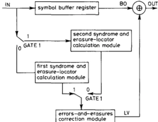
Fig. 1 shows the functional block diagram of the RS decoder for errors- and-erasures correction. The decoder is constructured by three basic modules: buffer module, syndrome and erasure-locator calculation module, and errors-and-erasures correcting module. The function of each module for the (15, 11) RS decoder will be described in the following. The symbols of the (15, 11) RS code are in GF(2,). For a received word r(x) = ro
+
r , X+ ...
+
r 1 4 X 1 4 , each of ri can be denoted by four binary digits for code symbol plus one binary digit for erasure flag. If the code symbol is an erasure, then set the corresponding erasure flag to 1, otherwise reset the erasure flag to 0. The syndrome values can then be found fromSi = r(ai)
= mod {r(X)/(X
+
ai)} for i = 1, 2, 3, 4erasure-locator errors-and-erasures correction module
9
0L-J GATE 1 LV1
Iwhere mod {r(X)/(x
+
a')} indicates the remainder of r(X) divided by X+
a! Furthermore, the syndrome values cyclically shifted j places to the right are defined asSi = mod { X j r ( X ) / ( X
+
a*)} for i = 1,2,3,4.In
practice, the syndrome values can be calculated by using four one-stage linear feedback shift registers (LFSRs) in hardware, and the shifted syndrome values can be obtained by shifting the contents of LFSRs with inputs blocked.EO
~
RESET RS CUI CU2 CU3 CUL UERR GATE4
t
I
Fig. 1 Block diagram oJRS decoder for error-and-erasure decoding
4.1 Buffer module
The buffer module is composed of 16 one-symbol shift registers in GF(2'). Each one-symbol shift register is con- structed by four binary shift registers linked in parallel. The first 15 symbol registers are used to store the received word, while the last one is used to latch the symbol which is shifted out and is ready for decoding. 4 2 Syndrome and erasure-locator calculation Fig. 2 shows the diagram of a syndrome calculation module and an erasure-locator calculation module. The
modules
erasure-locator calculation module calculates the erasure locators from the erasure-flag of the word.
The new algebraic decoding algorithm requires 2n shift operations for decoding one received word. The first n shifts are used to calculate the initial syndrome values and erasure-locators, the remaining n shifts are used to decode the errors and erasures in the received word. Since the number of shifts required for decoding errors and erasures is equal to that for calculating the initial syndrome values and erasure-locators, the calculation of syndrome and erasure-locator of the next received word can be performed at the same time. Thus, the average number of shifts required for decoding one received n- symbol block is just n. This line-speed decoding capabil- ity can be achieved by using two syndrome and erasure-locator calculation modules in the decoder struc- ture as shown in Fig. 1. The two modules interchange each other to calculate the syndrome values and erasure- locators of the received words. When a block is being shifted into the buffer module, the first syndrome and erasure-locator calculation module is working to calcu- late the syndrome values and erasure-locators of the current received block, while the second one holds the calculated syndrome values and the erasurelocators of the previous block which are ready for the errors-and- erasures correction modules and others. As soon as the current block is completely received, the calculated result from the first syndrome and erasure-locator calculation module is passed to the errors-and-erasures correction modules for decoding that block, and the second syn- drome and erasure-locator calculation module is enabled to calculate the syndrome values and erasure-locators of next received block.
4.3 Errors-and-erasures correction module
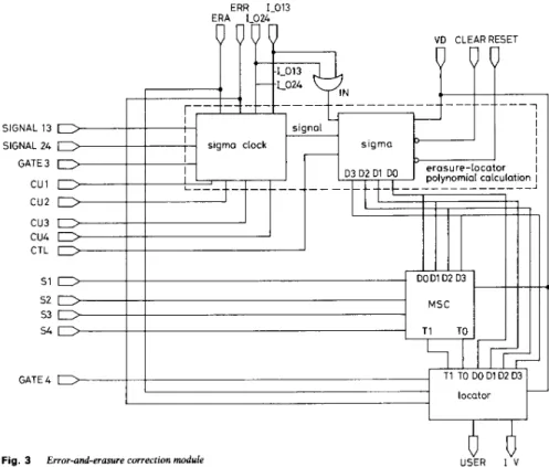
The errors-and-erasures correction module is used to cal- culate the error-locator and the erasure values from the calculated result of the syndrome and erasure-locator cal- culation module. The block diagram of the error-and-era- sures correction module is illustrated in Fig. 3, which comprises an erasure-locator polynomial calculation
W C K syndrome
I
S1 52 53 S 4 L024L013 ERR ERA
Fig. 2
I E E PROCEEDINGS-I, Vol. 140, No. 4 , A U G U S T 1993 Syndrome-and-erasure locator calculation module
I
circuit, a modified syndrome calculation circuit and an error-locator and erasure value calculation circuit.
only rn units of gate delay to complete the multiplication of two elements in GF(2") can be employed to increase
SlGh L 13 SIGNAL 24 GATE 3 cu 1 c u 2 c u 3 cu4 CTL 51 5 2 53 54 GATE 4 ERR 1-013 ERA 1-024
Fig. 3 Error-and-erasure correction module
The erasure-locator polynomial calculation circuit comprising a sigma circuit and a sigma clock is used to calculate the coefficients of the erasure-locator poly- nomial using the algorithm derived. The sigma circuit first set udq(x) = 1, then multiply udq(x) by ( X - Uq),
q = 1, 2, 3, 4. This circuit can be realised by three multi- pliers, four adders, and four pieces of one-stage LFSRs. The modified syndromes TI, To, and Tp can be obtained
from the syndrome values and the coefficients of the erasure-locator polynomial by the following equations :
Tl = O d l S 4
+
ud2 s 3+
ud3 ' 2TO= b d o s4
+
(TdlS3+
0 6 2 s2+
(Td3 SI = T pTherefore, the modified syndrome calculation circuit can be implemented by seven multipliers and five adders. As soon as the coefficients of the erasure-locator polynomial and modified syndrome values are known, error-locator ( U E R R ) or the erasure values ( L V ) can be obtained by
U E R R = Tl/To and
Lv = TO/('dO
+
u d l+
ud2+
u d 3 )4.4 Finite field multiplier, inverse and adder
The decoding speed of the decoder is dominantly deter- mined by the delay (computation time) of the multiplier. The multiplication of two elements in GF(24) can be achieved by using a rn = 4 cellular-array multiplier [lo]. Another type of Massey-Omura multipliers [ 111 taking 250
the decoding speed, although some extra basis invert operations should be added for transforming the ele- ments represented by a conventional basis { 1, a, a, a',
. . .
, am-'} into the ones represented by a normal basis { a , a', a4,. .
.
, For any a in the finite field GF(2"), aZm =a. Hence, the inverse of a is a - l = a'"-'. The inverse in GF(z4) can be accomplished by using combinational logic circuits, and the addition in GF(24) can be accomplished by using 2-input Exclusive-OR (XOR) gates.
4.5 Control module
Fig. 4 shows the required control signals for the (15, 11) RS decoder for error and erasure correcting. This module is implemented in Fig. 5. The function of each control signal is described in the following list.
(1) CK is the data rate of the received word.
(2) CKXS is an internal clock of the decoder, and its (3) VD is the DC voltage source.
(4) RESET is the initial reset of the decoder.
( 5 ) RS1 and RS2 are used to reset the syndrome and erasure-locator calculation modules after the results are computed and passed out for every 2n clock cycles which is the decoding time of a received block.
frequency must be at least 8 times faster than that of CK.
(6) IN is the serially received data input. (7) FLAG is the serial received erasure-flag.
(8) ERR is an indicator to indicate whether the decoder has error correction capability or not. If the received word contains no more than two erasures, then ERR = 1, which indicates that the decoder has one error IEE PROCEEDINGS-I, Vol. 140, No. 4, A U G U S T 1993
I
GATE 1
GATE 3 GATE4 RS1
correction capability; else ERR = 0, which indicates that 4.6 Operation sequence and simulation results the decoder can not correct any error. Assume that r ( X ) = r3 X4 + r , X7
+
r,X" is the(9) ERA is an indicator to indicate that there is an received block, where rl = 5, r , = 7, r 3 = 6, and rl is an erasure whose locator is 1. error, while r , , r 3 are erasures. The simulation results of
P W PnmrLnnl ~ ___--__ n n r7 n r -~ ~ CK CKX8 RESET 1 0 4000 8 0 0 0 12000 16000 20
Timing diagram of control signals
Fig. 4
(10) GATEl is the signal used to control some switch circuits of the decoder. GATEl will be low and high alternately for every n cycles. When GATEl is low, the current input symbols from IN will be switched to the first syndrome- and erasure-locator calculation module to calculate its initial syndrome values and erasure- locators. Then the calculated syndrome values and erasure-locators of the previous received block in the second syndrome and erasure-locator calculation module will be passed to the errors-and-erasures correction modules for further processing. After n clock cycles, GATEl will be high and the operations of the first and second syndrome and erasure-locator calculation modules alternate with each other.
(1 1) GATE3 will be high for one-half clock cycle after GATEl has changed. This signal is used to select the erasure-locator polynomial calculation circuit to calcu- late the coefficients of the erasure-locator polynomial.
(12) GATE4 will be high for one-half clock cycle after GATEl has changed one-half clock cycle. This signal is used to select the error-locator and erasure value calcu- lation module to calculate the error-locator U E R R and save U E R R as an erasure-locator. When GATE4 is low, the error-locator and erasure value calculation module is selected to calculate the erasure value LV.
(13) CUI, CU,, CU,, CU, are used to control the data input of the erasure-locator polynomial calculation module. When CUI (or CU,) is high, the current erasure locator LO1 (or L03) from the erasure-locator calcu- lation module is passed to the erasure-locator polynomial calculation module via the data bus L013. Similarly, when CU, (or CU,) is high, the current erasure-locator LO2 (or L04) from the erasure-locator calculation module is passed to the erasure-locator polynomial cal- culation module via the data bus L024.
(14) CLEAR is used to reset the sigma circuit after the proper coefficients of the erasure-locator polynomial are latched.
(15) SIGNAL13 and SIGNAL24 are the signals which are put into the sigma-clock circuit to synthesise SIGNAL, the LFSR triggering clock of the sigma circuit.
(16) CTL is the latch clock of the sigma circuit to latch the proper coefficients of the erasure-locator polynomial calculated by the sigma circuit.
(17) SAMPLE is the sampling clock to sample the final correct result after the error or the erasure symbol has been removed from the decoding symbol.
IEE PROCEEDINGS-I, Vol. 140, No. 4 , AUGUST 1993
I
1000 24000 28000 32000
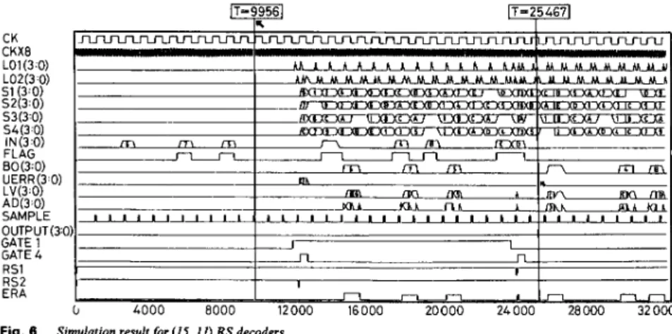
the (15, 11) RS decoder is illustrated in Fig. 6. The period of CKX8 equals to 50 time units and that of CK equals
to 800 time units. The operation sequence of the decoder is described as follows:
(1) In the first 15 cycles (time 0 to 12000), GATEl is slow, so r ( X ) is shifted into the buffer module and in the same time, syndrome values and erasure-locators are calculated in the first syndrome and erasure-locator cal- culation module.
(2) At time 12000, GATEl switches to high and the next word is ready for decoding, while the results calcu- lated in the first syndrome and erasure-locator calcu- lation module are switched to the errors-and-erasures correction module.
(3) At time 12400, GATE4 switches from low to high
to select the error-locator and-erasure value calculation module to compute the error-locator of the first received word and save the computed error-locator as erasure- locator. Since r3 is an error and its locator is a", the calculated U E R R is equal to EH, where H denotes the hexdecimal representation, GATE4 switches from high to low after the UERR is obtained.
(4) At time 12400, the highest order symbol of r ( X ) is shifted out and the syndrome values and erasure-locators in the first syndrome and erasure-locator calculation module are cyclically shifted once, while the first symbol of the next block is received and its syndrome values and erasure-locators are calculated in the second syndrome and erasure-locator calculation module.
(5) From time 12400 to time 24400, the error and erasure correction module checks each LSFRs of the erasure-locator. If one of the erasure-locators is found to be 1 (i.e. a'), then it indicates that the currently shifted out symbol is an erasure, and the erasure value LV will be calculated from the errors-and-erasures correction module.
(6) After the erasure value LV is known, LV is added to the output of the buffer module BO, which generates the output AD. The output AD is sampled at the rising edge of SAMPLE and the final decoded result of the first symbol of r(X) is obtained as the output OUT.
The simulation result in Fig. 6 illustrates that the error symbol rl of r ( X ) is found at time 15200 and the erasure symbols r , , r , are found at time 18400 and 20800, respectively. The final decoded word of r(X) will be zero which is a codeword of the (15, 11) RS code.
8 0 0
E
d
i
v
E l 0 1 2 '12012 LSZ ZSZ ESZ frsz fr31v9 "3fl N-
0 3 l d W V Sbas$
- N m U 3 3 3 3 v v v vE
2
w w E1011 'JZOlL 1Sl IS1 ES1 'JSL tlt13f-I 'J 31V9I
As described above, the calculation of the erasure- locator polynomial and the error-locator (or erasure values) must be completed within one CK cycle, where CK is the data rate of the received block. Therefore, the
values and erasure-locators corresponding to the first decoded symbol of the shortened RS code can be obtained by multiplying r(X) by X 8 before calculating syndrome and erasure-locators.
CK CKX8 LO1 (3 0) LOX3 0) 51 (3 0 ) SZ(3 0 ) 53(3 0 ) S4(3 0) IN(3 0 ) FLAG BO(3 0 ) UERR 3 0) AD(3 0) SAMPLE OUTPUT(3 0) GATE 1 GATE 4 RS1 RS2 ERA LV(3 00 4000 8 0 0 0 12000 16000 20000 24000 28000 32000
Fig. 6 Simulation result f o r (15, 11) RS decoders
working data rate of the decoder is dominantly deter- mined by the computation time of the errors-and-era- sures correction module, especially that of multiplications. The decoder works successfully when the period of CK is 800 time-units, assuming that one gate delay is one time-unit. Furthermore, if an IC technology with 0.5 ns gate delay is employed, for example 1.0 pm CMOS process, then the working data rate of this decoder will be up to 2M symbols/s.
5 Conclusion
A high-speed RS decoder for errors-and-erasures correc- tion based on a new algebraic decoding method has been presented. A serial structure which provides a general expression for calculating the erasure-locator polynomial is also proposed. Consequently, a (15,9) RS decoder with d,, = 7 can be also applied to decode the (15, 11) or (15, 13) RS code with dnin = 5, 3, respectively, by only modifying the control module. The (7, 3) RS code, a shortened code derived from (15, 11) RS code, can be decoded by the same decoder structure with slight modi- fication of the buffer module, syndrome and erasure- locator correction module, and control module. Since the block length of this code is 7, only 8 one-symbol registers are needed in the buffer module to store the received block and latch up the shifted-out symbol. The syndrome
Table 1 : G a t e c o u n t s of (15, 11) R S d e c o d e r a n d (7, 3) RS d e c o d e r Module Decoders (15. 11)RS (7. 3)RS Buffer 256 128 Syndrome 324 368 Erasure-locator 344 344 Modified-syndrome 469 469 Sigma-clock 25 25 Sigma 31 3 31 3 Error-locator and Erasure-value 145 145 Control 108 104 Other 277 277 Total 21 53 2069
I E E PROCEEDINGS-I, Vol. 140, No. 4, A U G U S T 1993
The numbers of gates required in the (15, 11) RS decoder and the (7, 3) RS decoder are shown in Table 1. A brief comparison in hardware complexity and compu- tation time between the standard algebraic decoding method and the new algebraic decoding method for RS decoder is also given in Table 2, where the chip area taken by a GF(z4) multiplier is defined as one unit a and a multiplier delay is defined as one unit mt.
Table 2: Comparison of s t a n d a r d a l g e b r a i c d e c o d i n g algo- r i t h m a n d n e w s t a n d a r d algebraic d e c o d i n g a l g o r i t h m f o r RS d e c o d e r
d,,, Standard algebraic New standard algebraic decoding method decoding method Complexity Delay Control Complexity Delay Control
clocks clocks
5 l l a 2mt Complex 4s lrnt Simple
7 17a 3mt Complex 6s lrnt Simple
6 References
1 BLAHUT, R.E.: ‘Theory and practice of error control code’ (Addison-Wesley, Reading, MA, 1983)
2 LIN, S., and COSTELLO, D.J. Jr.: ‘Error control coding: funda- mentals and applications’ (Prentice-Hall, Englewood Cliffs, NJ, 1983)
3 PETERSON, W.W., and WELDON, E.J. Jr.: ‘Error-correcting codes’(M1T Press, Cambridge, MA, 1972)
4 MICHELSON, A.M., and LEVESQUE, A.H.: ‘Error-control tech- niques for digital communication’ (Wiley, New York, 1985) 5 FORNEY, G.D. Jr.: ‘On decoding BCH codes’, IEEE Trans.
lnjorm. Theory, Oct. 1965, IT-11, pp. 549-557
6 SHAO, H.M., TRUONG, T.K., DEUTSCH, L.J., YUEN, J.H., and REED, I.%: ‘A VLSI design of a pipeline Reed-Solomon decoder’,
IEEE Trans. Cornput., May 1985, C-34, pp. 393-402
7 SHAO, H.M., and REED, IS.: ‘On the VLSI design of a pipeline Reed-Solomon decoder using systolic arrays’, IEEE Trans. Comput.,
8 WEI, S.W., and WEI, C.H.: ‘High speed hardware decoder for double-mor-correctina binary BCH codes’. Proc. 1EE. June 1989. Oct. 1988, C-37, pp. 1273-1280
136, Pt. I, (3), pp. 227-231
9 WEI, S.W., and WEI, C.H.: ‘On high-speed decoding of the (23, 12,
7) Golay code’, IEEE Trans. Injorm. Theory, May 1990, IT-36, (3). pp. 692-695
10 LAWS, B.A., and RUSHFORTH, C.K.: 'A cellular-array multiplier for GF(2")', IEEE Trans. Cornput., Dec. 1971, C-20, pp. 1573-1578 11 WANG, C.C., TRUONG, T.K., SHAO, H.M., DEUTSCH, L.J.,
OMURA, J.K., and REED, IS.: 'VLSI architecture for computing multiplications and inverses in GF(2")', IEEE Trans. Cornput., Aug. 1985, C-34, pp. 709-716
12 KIM, S.W.: 'Error control codes for digital recording systems', IEEE Trans. Consumer Electronics, Nov. 1989, 35, (4), pp. 907-916
13 GOTO, H., ASADA, A., CHIBA, H., SAMPEI, T., NOGUCHI, T., and ARAKAWA, M.: 'A new concept of DATAPAT system', IEEE Trans. Consumer Electronics, Aug. 1989.35. (3). pp. 660-670 14 HAYASHI, K.: 'Error correction method for R-DAT and its evalu-
ation', IEEE ICASSP, Tokyo, 1986, pp. 9-12
15 CLARK, G.C. Jr., and CAIN, J.B.: 'Error-correction coding for digital communications' (Plenum Press, New York, 1982)