July 1, 1994 / Vol. 19, No. 13 / OPTICS LETTERS 939
Effect of cross-phase modulation on optical phase
conjugation in dispersion-shifted fiber
Senfar Wen
Department of Electrical Engineering, Chung-Hua Polytechnic Institute, 30 Tung Shiang, Hsinchu, Taiwan, China Sien Chi and Tze-Chung Chang
Institute of Electro-Optical Engineering, National Chiao Tung University, 1001 Ta Hsueh Road, Hsinchu, Taiwan, China
Received January 31, 1994
The temporal effect of optical phase conjugation in dispersion-shifted fiber is studied numerically. Frequency chirping is induced in the conjugate pulse by the signal pulse and the pump wave through cross-phase modulation, which increases with the signal power and may distort the pulse shape when the conjugate pulse propagates in the
standard fiber. It is also shown that, when the signal power is low, the optical phase conjugation is nearly ideal.
Recently several experiments showed that chromatic dispersion can be compensated by the optical phase conjugation (OPC) in the fiber."2 The idea to use the OPC to compensate the dispersion was proposed more than a decade ago.3 It has become an impor-tant issue because of the introduction of the erbium-doped fiber amplifier. The operating wavelength of the erbium-doped fiber amplifier is in the 1550-nm band, where the dispersion is high for the standard fiber (STF). To compensate for the fiber loss with the erbium-doped fiber amplifier without sacrificing the bit rate, one needs to overcome the fiber dis-persion. The OPC is generated by four-wave mix-ing in the dispersion-shifted fiber (DSF), in which the pump wavelength is at zero dispersion and the phase-matching condition is satisfied.4 In this Letter we will solve the wave equation to study the temporal effects in the process and verify whether the conjuga-tor is ideal. It is found that there is frequency chirp-ing in the conjugate pulse that is due to cross-phase modulation (XPM) among the conjugate pulse, signal pulse, and pump wave, which may distort the pulse. With the carrier exp[i(,foz - not)], where co is the zero-dispersion frequency, the complex envelope of the electric field propagating in the fiber can be written as5
i
az 62
-i613 a
+ =,--
ia§.
(1)Here A33 represents the third-order dispersion at oo; y = n2co/cAeff, where n2 is the Kerr coefficient and Aeff is the effective fiber cross section; and a is the fiber loss. The term with y in Eq. (1) is usually used to represent self-phase modulation. In fact, it in-cludes all four-wave mixing that is due to the Kerr nonlinearity, for example, XPM and OPC. To show these effects we may decompose the electric-field en-velope as
0 = qp +
qSexp(-iflt)
+
4bexp(ift),
(2)
where Op is the pump wave with frequency cop = co0 and .0, and Xc are the signal wave and the conjugate
wave with frequencies
co.
=coo
+fl
andco,
= wo - Q. respectively. Since the slowly varying envelope ap-proximation is assumed in the derivation of Eq. (1),it is required that If
I
«o.
<<
Substituting Eq. (2)
into Eq. (1) and neglecting the high-frequency com-ponents, we have id
-_
i 1P3a
3U +y(I4pl
2 + 214,e,2 + 214c12)0p+ 2y.O..,p*= -
ia p
2 (3a)i
ao.
+
I
,130.+
+ i
2 i~fl2d'k -
_i
'
2 .azk 18 16 2 at 2 3f at2. 1
a4,s_
8 I .1 .12 O1)O - I At3 +v(bk
81
2 + 2I~c12 + 21plI)q$ + yoP2,"*= - 2
iaons b (3b) i - 83 fl 3Q + i 23flQ2ao
+ 263Q a2
az 6 ai- 83- at3 + v(II 2 + 2I12 + 21bpI2)q + y.bp2k8* = ia4ic,
(3c) where the terms with the time derivations represent the dispersions of the fields. In Eqs. (3) the terms that represent the XPM can be clearly seen. The last terms in the left-hand sides of Eqs. (3) represent the four-wave mixing that is responsible for the OPC. In our calculations we take A3 = 7.4 X 10-41 s3/m,
n2= 3.2 X 10⁻²⁰ m2/W, and Aeff = 35 /m 2. As an ex-ample, we take the propagation of a Gaussian pulse, which is assumed to be
Al =
\Aj exp
2 (2t/l)! X (4)940 OPTICS LETTERS / Vol. 19, No. 13 / July 1, 1994
power of the conjugate pulse at A, = 1550.5 nm along
P2= 8 mW the DSF for P, = 8 mW and various signal powers
P2. It is seen that the power of the conjugate pulse
increases with the signal power and that the
opti-l ^z~
P2= I MW
~
mum length is -20 km, which agrees well with the experiments. At the optimum length the instan-taneous frequencies Aco of the conjugate pulses with different P2 values are shown in Fig. 2, for whichI= / 3w6 = -aql/at and f is the phase of the pulse. In
Fig. 2 the Aco of the input signal pulse is also shown for comparison. The frequency chirping of the input pulse is due to chromatic dispersion and self-phase modulation in the STF. One can see that the ac of the conjugate pulse is inverted with respect to the
0 10 20 30 40 signal pulse. When P2 is low 8co is almost equal
to the negative 3co of the input pulse. When P2 is
DISTANCE z (km) high there is additional frequency chirping that is k powers of the conjugate pulses along the due to the XPM from the signal and the pump wave. W pump power and various signal powers P2. The pulses broaden only slightly in the DSF because
7 6 --- INPUT 5 NP 2=0. 1 A \~~~~~~~ Z -2 4 P2: -2 --4 -6 -7 --200 -100 0 100 200 5 4 3 2 N 1 0 V9 N1 -1
'a
-2
-3 -4 -5 TIME t (ps)Fig. 2. Instantaneous frequencies 3c of the conjugate pulses after they propagate 20 km in the DSF for the cases shown in Fig. 1. The 8co of the input signal pulse is also shown.
where P1 and r1 are its initial peak power and
pulse width, respectively. The carrier wavelength A, = 1542.9 nm. The pulse at first propagates in a 80-km-long STF with a 0.22-dB/km loss and 16-ps/(km nm) dispersion. The Kerr coefficient and effective fiber cross section of the STF are assumed to be the same as the DSF for simplicity. We take
P1 = 1.43 mW and rT = 100 ps. At the end of
the fiber the pulse broadens, and its pulse width becomes 116.9 ps. The pulse is then amplified to a peak power of P2 and is launched into the DSF
with a zero-dispersion wavelength at 1546.7 nm and a 0.24-dR/km fiber loss. The coupling loss is neglected for simplicity. The pump wave is at the zero-dispersion wavelength and has a power of Pp. Thus the initial condition used to solve Eq. (1) is
-200 -100 0 100 200
TIME t (ps)
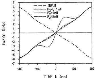
Fig. 3. Instantaneous frequencies 8co of the conjugate pulses after they propagate 80 km in the STF. The cases obtained from various signal powers P2 are shown, as well
as the co) with ideal OPC.
(0 -CD LLu U-0.5 0 -200 -100 0 100 200 qS
=
p+ 02 exp(-ift),
(5)where the pump wave is a continuous wave, 102 is
the input signal pulse, and fl is the frequency devia-tion from the pump wave. Figure 1 shows the peak
Fig. 4. Corresponding p
pulses shown in Fig. 3. by Eq. (4) is also shown. are normalized.
TIME t (ps)
pulse shapes of the conjugate The original pulse shape given The amplitudes of the pulses
1x10 -g 5x10⁻² E = 1 x1 0-2 1 5x10³ 51 Lii oL 5x10⁻⁴ I xi 0-5X 0-5 Fig. 1. Pea DSF for 8-m
July 1, 1994 / Vol. 19, No. 13 / OPTICS LETTERS 941
of low dispersion. After propagating 20 km in the DSF the pulse widths of the conjugate pulses be-come 116.8, 117.2, and 120.4 ps for P2 = 0.1, 1, and 8
mW, respectively. Unlike the case of the input pulse width, there is almost no further pulse broadening in the DSF when P2 is low. The broadening increases
with the signal power because of the broadening of the signal pulse, which is enhanced by the frequency chirping that is due to self-phase modulation because its wavelength is in the positive dispersion regime in the DSF. From Eqs. (3b) and (3c) the group veloci-ties of the signal and conjugate pulses are the same. Since there is no walk-off between the two pulses the shape of the conjugate pulse follows the signal pulse. The walk-off between the pump wave and the pulses is only 6.6 ps after the pulses propagate 20 km. Be-cause the walk-off is small there is a dip on the part of the pump wave that overlaps the pulses as a re-sult of the pump depletion, which increases with the signal power. After the pulses propagate 20 km in the DSF the relative power depth of the dip is 0.32%, 3.17%, and 21.8% for P2 = 0.1, 1, and 8 mW,
respec-tively. This shows that the contribution of the pump wave to the XPM is small compared with the signal pulse in these cases. We take the conjugate pulse at 20 km as the output pulse, which is then am-plified so that its pulse energy is the same as that launched into the first STF and so that it propagates along the second STF. From the theory of OPC the pulse shape of conjugate pulse will be restored when the pulse experiences the same chromatic dispersion that is experienced by the original pulse. Since A. and A, are nearly equal we assume that the disper-sion of the second STF at A, is the same as that of the first STF at A,, for simplicity. Figures 3 and 4 show the 3co and pulse shapes, respectively, of the conjugate pulses obtained from various P2 values
af-ter the pulses propagate 80 km. In Fig. 4 the orig-inal pulse shape given by Eq. (4) is shown for com-parison. Figure 3 also shows the 8o curve that we calculated by assuming. ideal OPC, for which the res-ident frequency chirping is due to the combined ef-fect of the dispersion and self-phase modulation in the STF. The combined effect cannot be compensated
completely by the OPC in the lossy medium.6 We can reduce such a resident frequency chirping by de-creasing the input powers to the STF's. One can see that, for the case with a low P2, 8co is almost the same
as the ideal case; i.e., the OPC in the DSF is nearly ideal, and the pulse shape is restored. When P2 is
high there is significant resident frequency chirping that is due to the XPM from the signal pulse and the pump wave in the DSF. As Fig. 4 shows, the pulse is distorted for such a case. Although its width nar-rows, the signal pulse will be seriously distorted on further propagation in the STF's, and there will be dispersive waves spreading out, which are not shown here. Therefore for long-distance propagation, with the fiber dispersion periodically compensated by the OPC, it is not desirable to use high signal power to amplify the conjugate pulse.
In conclusion, we have shown frequency chirping of the conjugate pulse that is due to the signal pulse and the pump wave through XPM in the DSF. When the signal power is high the power of the conjugate pulse is amplified, but the frequency chirping is enhanced, which leads to pulse distortion when the conjugate pulse propagates in the STF. It has also been shown that, when the signal power is low, the OPC is nearly ideal.
This study is supported by the National Science Council of China under contract NSC 83-0417-E009-013.
References
1. S. Watanabe, T. Naito, and T. Chikama, IEEE Photon. Technol. Lett. 5, 92 (1993).
2. R. M. Jopson, A. H. Gnauck, and R. M. Derosier,
Elec-tron. Lett. 29, 576 (1993).
3. A. Yariv, D. Fekete, and D. M. Pepper, Opt. Lett. 4, 52
(1979).
4. K Inoue and H. Toba, IEEE Photon. Technol. Lett. 4,
69 (1992).
5. G. P. Agrawal, Nonlinear Fiber Optics, 1st ed. (Aca-demic, Boston, Mass., 1989), p. 40.
6. R. A. Fisher, B. R. Suydam, and D. Yevick, Opt. Lett. 8, 611 (1983).