A Graph Approach to Quantitative Analysis of
Control-Flow Obfuscating Transformations
Hsin-Yi Tsai, Yu-Lun Huang, and David Wagner
Abstract—Modern obfuscation techniques are intended to
dis-courage reverse engineering and malicious tampering of software programs. We study control-flow obfuscation, which works by modifying the control flow of the program to be obfuscated, and observe that it is difficult to evaluate the robustness of these obfuscation techniques. In this paper, we present a framework for quantitative analysis of control-flow obfuscating transfor-mations. Our framework is based upon the control-flow graph of the program, and we show that many existing control-flow obfuscation techniques can be expressed as a sequence of basic transformations on these graphs. We also propose a new measure of the difficulty of reversing these obfuscated programs, and we show that our framework can be used to easily evaluate the space penalty due to the transformations.
Index Terms—Code obfuscation, computer prime, reverse
engi-neering, software metrics, software protection.
I. INTRODUCTION
T
HE protection of software programs against illicit access is an important issue for many software companies. Since the mid 1990s, digital rights management (DRM) [1], [2] has been used to control unauthorized duplication and illegal piracy and, thus, protect the profits of publishers and owners of this software. DRM can be implemented by injecting a self-checking code into a program. This verification code is typically executed before the original program to verify the authority of the user and check that the program is being used as intended. However, attackers can still try to reverse engineer the resulting program and skip or remove the verification code if its location is not well hidden.Recently, advanced techniques, such as software encryption [3]–[5] and software obfuscation [6]–[16] have been proposed to protect the verification logic in DRM-protected programs. In the software encryption approach, the program is encrypted and self-decrypted upon execution. Unfortunately, this can neg-atively affect performance. In comparison, code obfuscation works by transforming an application so that the transformed program will be functionally identical to the original one but with much greater resistance to reverse engineering. The Manuscript received May 11, 2008; revised October 06, 2008. First published February 13, 2009; current version published May 15, 2009. This work was sup-ported in part by the iCAST Project and TWISC, sponsored by the NSC under Grants NSC96-3114-P-001-002-Y, 001-001, NSC95-2218-E-011-015, and NSC-97-2918-I-009-005. The associate editor coordinating the re-view of this manuscript and approving it for publication was Dr. Jana Dittmann. H.-Y. Tsai and Y.-L. Huang are with the Department of Electrical and Control Engineering, National Chiao-Tung University, Taiwan 300.
D. Wagner is with the Department of Electrical Engineering and Computer Sciences, University of California at Berkeley, Berkeley, CA 94720 USA.
Digital Object Identifier 10.1109/TIFS.2008.2011077
promise of obfuscation is that obfuscated applications can run on an untrusted platform without the risk of reverse engineering, tampering, or intellectual property thefts. Code obfuscation techniques require no extra hardware and are platform inde-pendent and, as a result, they provide greater flexibility in how programs may be deployed.
Collberg et al. [9], [10] classified obfuscating transformations and proposed several approaches to program obfuscation. One approach is control-flow obfuscation, which tries to disguise the real control flow in a program by reordering and obfuscating the execution paths and structure of the original program. This pro-vides a candidate way of trying to hide self-checking verifica-tion logic in the obfuscated program, thereby making that logic difficult to bypass or remove. There have been many proposals on how to perform control-flow obfuscation; however, earlier works are unable to clearly quantify the security of these con-trol-flow obfuscation methods against reverse engineering.
This paper presents an abstract framework for formalizing and modeling many kinds of control-flow obfuscation algo-rithms. In this framework, we describe an obfuscation scheme as a transformation on program control-flow graphs (CFG). A control-flow obfuscation algorithm can be viewed as a function that accepts the original program’s CFG as input and yields a modified CFG. By analyzing many existing control-flow obfuscating transformations, we observed that many of them can be decomposed into a sequence of basic building blocks. Thus, we identify a set of atomic operators for simple graph transformations that are guaranteed to preserve the functional behavior of the program and, hence, can be used as building blocks of a control-flow obfuscation algorithm. By composing instances of these atomic operators in sequence, we can build many kinds of control-flow obfuscating transformations. This helps to understand and classify many prior control-flow ob-fuscation proposals and may help in devising new candidate control-flow obfuscation methods.
We show that our framework helps to statistically analyze and evaluate control-flow obfuscating transformations. The frame-work only focuses on statically obfuscated source programs, and cannot be apply to dynamic analysis of reverse engineering. We also show how to evaluate the overhead on code size in-troduced by a control-flow obfuscation method that can be ex-pressed within our framework. Our approach works by charac-terizing the space penalty of each individual atomic operator. We propose a metric that we conjecture may be related to the ro-bustness of the obfuscated program against reverse engineering. We hope that these evaluation techniques will help to evaluate the tradeoff between the effectiveness and the overhead of dif-ferent obfuscation methods.
The novel contributions of this paper are as follows. • We propose a framework with a reasonable set of atomic
operators. This framework is flexible enough to adopt other types of operators as well.
• We show how to systematically formalize many existing control-flow obfuscation techniques by characterizing them as a functional composition of our atomic oper-ators. These operators can also be used to design new control-flow obfuscating transformations.
• We propose metrics that we conjecture may be helpful in evaluating the performance and robustness of control-flow obfuscation techniques built in this framework.
This paper is organized as follows. In Section II, we give an overview of related work. Section III reviews the background of CFGs and Section IV describes the proposed atomic operators. The formalization of the control-flow obfuscating transforma-tions is specified in Section V. Section VI proposes a metric for evaluating the robustness of transformations and we analyze the overhead of these transformations on code size in Section VII. Finally, Section VIII gives an example and the conclusion is in the last section.
II. RELATEDWORKS
There are several types of obfuscating transformations [6]–[11], including layout obfuscation, data obfuscation, con-trol-flow obfuscation, and preventive transformation. Since the control flow of a program reveals the structure of the program logic, the CFG is very helpful to a deobfuscator; consequently, to be useful for preventing reverse engineering, a program obfuscation method should obfuscate the structure of the program’s control flow. Control-flow obfuscation hides or restructures the flow of execution of the program and, thus, makes reverse engineering more difficult. Techniques used for control-flow obfuscation include branch insertion, code reordering, and loop condition insertion transformation. A brief survey of these techniques will be given.
Branch insertion [9] works by inserting opaque predicates into a program to disturb and conceal the real control flow. An opaque predicate is a Boolean-valued expression whose value is known a priori to an obfuscator but is difficult for a deob-fuscator to deduce. These opaque predicates can be categorized into three types [9]: 1) a type I opaque predicate always evalu-ates to false; 2) a type II predicate always evaluevalu-ates to true; and 3) a type III predicate can sometimes evaluate to true and some-times to false. In this paper, we denote these predicates by ,
, and , respectively.
When a is used, the original code is moved to the false target of the predicate to maintain the same functionality. Sim-ilarly, the original code is moved to the true target for a . With a , the original code is placed on one branch target while the other must contain some functionally equivalent copy of the original code (since we do not know in advance which branch will be taken).
The code reordering obfuscation [8] randomizes the order in which independent instructions of a program appear so that the spatial locality of the instructions will not reveal the relationship among the instructions, nor provide useful clues to the execution
logic of the program. Reordering focuses on jumbling the place-ment of code sections in a source program.
Loop condition insertion [8] intends to increase the com-plexity of a loop by extending its conditions. This kind of transformations use and to make branch conditions more complex and further increase the difficulty of reverse engineering.
III. CONTROL-FLOWGRAPHS
CFGs were developed by Cota et al. [17], [18] as a representa-tion of the control-flow structure of a program. We use CFGs to facilitate the formalization of obfuscating transformations. We review some basic concepts and introduce the notations repre-senting the program’s CFG.
As a high-level abstraction, a software program is composed of a sequence of code blocks. The program can be converted into a directed graph whose vertices are its code blocks. There is an edge between two code blocks if the second code block can be executed immediately after the first. In this paper, a code block is either a branch instruction or a sequence of nonbranch instructions, with notations as follows.
• Branch : A branch refers to an instruction that can cause execution to transfer, either conditionally or uncon-ditionally, to some statement other than the immediately following statement. In high-level programming lan-guages, branch instructions may be found in , ,
- , - , and statements.
• Simple block : A simple block is defined as an ordered sequence of statements without outgoing or incoming branch instruction inside this code block.
We will use the following notation for several special kinds of code blocks:
• entry block : the entry point of a source program; • any block : any existing code block, or a dummy code
block that has been inserted to the program without affecting the final execution result;
• equivalent block [ ]: a code block that is functionally equivalent to the code block ;
• termination block : the exit point of a source program. The edges in a directed graph of a software program repre-sent possible executing paths that the program might take. We introduce two kinds of edges as follows.
1) Sequential edge : A sequential edge is
defined for two code blocks and (where )
if the execution of is always immediately followed by executing .
2) Branch edge : Since a branch instruction may jump to either its true or false target, there are two code blocks that could be executed after . The two branch edges
leaving are represented as and
, where and represent the
true and false targets of , respectively.
The directed graph can be represented by the pair ( , ), where is the vertex set and is the edge set. contains all of the code blocks of the parsed program, including simple blocks, branches, and a termination . is composed of sequen-tial edges and branch edges. Then, a software program is a pair
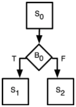
Fig. 1. Example of the formal representation of a parsed program.
is an indication of the end of the execution path, no code exists in this vertex. Hence, it is not counted into the total number of the vertex set . Fig. 1 shows an example of a program graph which contains three simple blocks and one branch, where
, , , and
. IV. ATOMICOPERATORS
A program graph is a complete representation of a source pro-gram. Obfuscating the control flow of a program can be viewed as converting one program graph to another. For graph conver-sion, we can use deletion, addition, and update. With deletion, a vertex or an edge is removed. As deletion always alters the functionality of the original code, we do not use deletion for pro-gram obfuscation. Addition inserts additional edges or vertices, and update means to modify the existing vertices in the graph. Although addition and update may also change the execution result, dummy or redundant codes can be used to maintain the original functionality. Therefore, control-flow obfuscation may involve two classes of operators: insertion and update. We de-scribe these two sets of atomic operators, called “operators” and denoted by “ ” hereafter.
A. Insertion
Since the code blocks are classified into only two types: 1) simple blocks and 2) branches, inserting vertices means inserting simple blocks or branches. To insert simple blocks without affecting the original functionality, we can insert dummy blocks that do nothing but resemble real code. Inserting branches can be realized by inserting opaque predicates and dummy loops.
1) Insert Dummy Simple Blocks: The insertion of dummy
codes changes the control flow of a source program. Fig. 2 ex-hibits the operator representing the insertion of a dummy simple block in front of the target code block . The graph on the right-hand side is the CFG of , which represents a result after applying to in . In , all edges whose successor or true/false target is would be replaced. An additional sequential edge ( , ) is also inserted for the edge set .
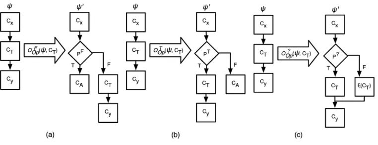
2) Insert Opaque Predicates: The opaque predicates can be
applied by inserting branches for obfuscation to preserve the same execution result. The insertion can be accomplished by inserting the three types of opaque predicates to hide the real
Fig. 2. Operator of inserting a dummy simple block. After insertion,E be-comesf(C ; C ); (C ; C ); (C ; C )g.
control flow of a source program. , , and
repre-sent the three types of insertion: type I (false), II (true), and III, respectively.
type I) : As is inserted in front of the target block , should be moved to the false target of to maintain the same functionality [see Fig. 3(a)]. Since the execu-tion result of is always false, any code block may be specified as the true target of . can be an ex-isting or a dummy code block by applying the operator
.
type II) : The procedure for inserting is similar to that for [see Fig. 3(b)]. Since always evaluates to true, is placed as the true target of . , any code block, can be its never-reached false target.
type III) : Fig. 3(c) shows the actions of . To ensure the same functionality, the equivalence of is placed on one of the targets of .
3) Insert Dummy Loops: A loop can be achieved by
com-bining simple blocks and branches. The operator inserts an extra loop in front of the target block as shown in Fig. 4. If is the successor of a sequential edge or the true/false target of a branch edge, it will be replaced by a dummy branch .
Then, a new sequential edge and two additional
branch edges , and are inserted into
the edge set, where is a dummy simple block. In this way, a loop composed of and is constructed.
B. Update
We consider splitting, reordering, and replacing operators for modifying a vertex.
1) Split Code Blocks: Splitting a code block into pieces can
increase the number of vertices in the CFG and increase its com-plexity. Combining the splitting operator with other operators helps implement more complex obfuscating transformations. In the following actions, the operators of splitting simple blocks and splitting branches are explained.
• : The operator aims at splitting a simple block into
pieces. In Fig. 5, splits into pieces,
Fig. 3. Operators of inserting opaque predicates: (a) Type I, (b) Type II, and (c) Type III.
Fig. 4. Operator of inserting dummy loops. After insertion E = (C ; C ); (C ; C ) ;(C ; C ) ; (C ; C ); (C ; C )) .
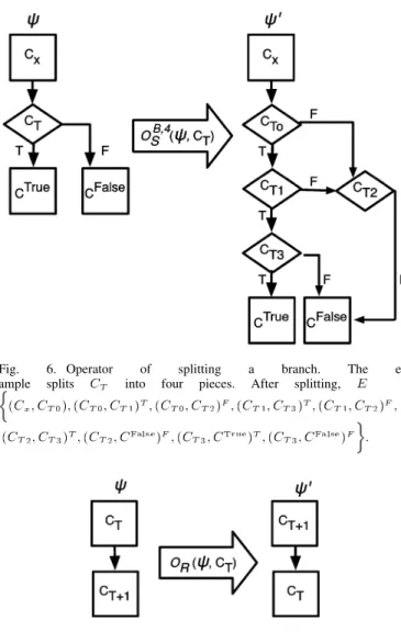
• : The operator splits a target branch into smaller pieces. Similarly, the parameter is limited to the numbers of conditions in . In Fig. 6, can be
ex-pressed as .
Since there are four conditions in , is limited to 4. These conditions are first converted to postfix orders . After splitting , the original CFG is then converted to the CFG on the
right-hand side, where , , , and represent
, , , and , respectively.
2) Reorder Code Blocks: Randomizing the placement of
in-structions helps to hide the original execution logics from being reversely engineered. The reordering operator then becomes one of the operators in obfuscating programs (see Fig. 7). Before applying , the execution dependency between and its im-mediate successor should be checked. If dependency ex-ists, then may result in an incorrect execution.
3) Replace With Equivalent Codes: Equivalent codes are
those that have the same execution result as the origins, while
Fig. 5. Operator of splitting a simple block. After splitting, E = f(C ; C ); (C ; C ); . . . ;(C ; C ); (C ; C )g. their implementations are different. The equivalent codes con-duce to confuse reverse engineers. The operator
re-places in with its equivalent code .
V. FORMALIZATION OFOBFUSCATINGTRANSFORMATIONS A control-flow obfuscating transformation can be decomposed into a sequence of operators. Different se-quences of operators lead to different transformations. Even with the same sequence, specifying different target blocks to these operators may obtain different results.
We represent a transformation as
the composition of operators , where
, for
. Note that stands for an ordered set of functional
composition, where represents the function
defined by .
Fig. 6. Operator of splitting a branch. The ex-ample splits C into four pieces. After splitting, E =
(C ; C ); (C ; C ) ; (C ; C ) ; (C ; C ) ; (C ; C ) ; (C ; C ) ; (C ; C ) ; (C ; C ) ; (C ; C ) .
Fig. 7. Operator of reordering code blocks. After reordering,f(C ; C )g is replaced withf(C ; C )g.
This formal model can be used to describe many existing con-trol-flow transformations [6], [9], [12]–[16], according to their algorithms. Decomposing these transformations into a sequence of operators also enables further analysis. Table I classifies 17 existing transformations according to whether they can be repre-sented as a functional composition of our operators. As the table shows, ten transformations can be decomposed into a sequence of the proposed operators, but six of them cannot. In this section, we detail the decomposition, justify each entry in the table, and interpret these results.
A. Basic Block Fission Obfuscation [6]
This obfuscation tries to subvert the structures of programs so that decompiling the transformed programs would be unsuc-cessful. This transformation splits the chosen code blocks into more pieces, and inserts opaque predicates and instruc-tions into these pieces. In the example presented in [6], to pro-tect against the decompilation attack, a few more blocks were generated and inserted after splitting the chosen code blocks. Then, a type I opaque predicate was inserted to make sure of the unreachability of the newly inserted code blocks and, thus, functionality of the original program was preserved.
TABLE I
FEASIBILITY OFDECOMPOSITION
In this case, according to the type of the chosen code blocks, we can apply to a simple block or to a branch. More-over, and can be used to insert dummy code blocks. Type II opaque predicates are used to perform the function-ality of instructions while any one of three opera-tors can be inserted as opaque predicates to realize the basic block fission obfuscation. Thus, this transformation can be
ex-pressed as , where ,
, , and .
B. Intersecting Loop Obfuscation [6]
This obfuscation inserts two intersected loops to a source program to make control flows unrecognizable for decom-pilers. Also, a type I opaque predicate is inserted to skip the newly inserted intersecting loops and to avoid any influence upon the original execution. Since a loop consists of a simple block and a branch, we use two simple blocks and two opaque predicates to create the two intersected loops. To preserve the same execution, the newly inserted loops are followed by a type I opaque predicate. Hence, this transformation can
be expressed as , where
.
C. Replacing Obfuscation [6]
This obfuscation replaces instructions with conditional branch instructions that do not influence the original control flow. This can be realized by replacing the go to instructions with their equivalent codes. The transformation can be
repre-sented as , where for
.
D. Branch Insertion Transformation [9]
This transformations is designed based on one of the three
opaque predicate insertion operators , , and .
It can be expressed as . The target
block is first split into two pieces by .
. Finally, the insertion of dummy
codes is optional in this transformation.
E. Loop Condition Extension Transformation [9]
A loop can be obfuscated by complicating the loop condition. The idea is to extend the loop condition using opaque pred-icates that do not affect the iterations when the loop is exe-cuted. The targets of opaque predicates are the branch blocks forming the loop condition. These opaque predicates are in-serted immediately in front of the branch blocks. Optionally, a dummy code block can also be placed in its never-reached target. The formal representation of this transformation can be
defined as , where
and (optional).
F. Language-Breaking Transformation [9]
This transformation converts a reducible flow graph to a nonreducible one by turning a structured loop into a loop with multiple headers. For obscurity, the loop body is split into two pieces. A type I or type II opaque predicate is inserted in front of the original loop to make a never-executed jump into the second split piece. Since it is a never-executed jump, the second split piece is placed on the never-executed target of the inserted opaque predicate. The expression in terms of the operators is
defined as , where is the operator to
split a code block into two halves , and
is optional.
G. Parallelize Code [9]
A reverse engineer may find a parallel program more difficult to understand than a sequential one. Thus, parallelization may lead to higher potency. To increase parallelism for obscuring the control flow of a program, we can either create dummy processes or split a code block into multiple data-independent blocks executing in parallel. Since parallel execution cannot be expressed using a simple graph representation, it fails to decom-pose this transformation in our framework.
H. Add Redundant Operands [9]
Algebraic laws can be used to add redundant operands to arithmetic expressions. The logic of the original expression is modified, and the operation becomes more complex. The
trans-formation is formalized by , where
for . Only the method “add redundant codes”
can be used as the technique of the creation of equivalent codes for the operator .
I. Aggregation Transformations [9]
This transformation falls into two categories. One is to break up codes where programmers aggregated them into a method and scatter the codes over the program. The other is to aggregate the codes which seem to not belong together into one method. Since operators are mainly applied to code blocks, this trans-formation with the basis of methods cannot be represented by using our operators.
J. Ordering Transformations [9]
To eliminate useful spatial clues to understand the execution logics of a program, ordering obfuscation was proposed to ran-domize the placement of any code block in a source program. The operator is used to express the ordering
trans-formations in the form where
for . Note that exchanges the two target blocks
if no dependency exists between them.
K. Remove Library Calls and Programming Idioms [9]
It is known that the standard JAVA library calls may provide useful clues to reverse-engineers. To impede this problem from being exacerbated, an obfuscator may provide its own versions of the standard libraries. If this transformation is designated to apply to code blocks, instead of programs, the target block can be replaced with its equivalent codes and expressed as follows.
, where for .
L. Table Interpretation [9]
This transformation converts a code block into a different vir-tual machine code which is then executed by a virvir-tual machine interpreter within the obfuscated program. Since we do not talk about interpreters in this paper, it fails to formalize this trans-formation with the proposed operators.
M. Degeneration of Control Flow [12]
This transformation converts high-level control structures into equivalent if-then-goto constructs. Then, statements are modified such that the target addresses of the state-ments are computed at runtime. In the first step, the expected construct can be developed according to the proposed CFG. Since the transformation replaces control flow with com-puted- statements, equivalence techniques can be used to generate the target blocks of the statements. Subsequently, can be applied to branches of the construct to dynamically determine the target address of the instructions. Thus,
the transformation can be expressed as ,
where for .
N. Obfuscation Scheme Using Random Numbers [13]
In this transformation, a dispatcher uses a random number (RN) to determine its target method while a method point (MP) is used to check whether the selected target method should be executed or not. If RN MP, the selected method is not exe-cuted. The transformation regenerates a random number to se-lect another method until RN matches MP.
The concept of using a dispatcher and a random number can be accomplished by the obscurity and randomness of type III opaque predicates. Here, a type III opaque predicate is inserted in front of each method designated as the true target of the pred-icate. If the predicate evaluates true, its corresponding method is reached; otherwise, the execution jumps to another predicate with the same functionality as the former. Since MP is used to determine the accurate execution path, we insert other type III opaque predicates for each method, where the newly inserted
predicates play the same role as MP. Hence, the
transforma-tion can be expressed in the form , where
for .
O. Obfuscating C++ Programs Via Flattening [14]
The transformation is to first break up the function body into several smaller blocks and then make the blocks in the same nesting level. Besides, a dispatcher determines which equal-lev-eled blocks are to be executed. Although we can adopt the same way for the implementation of the dispatcher, we cannot carry out the main idea of this transformation that the split blocks are in the same nesting level. Therefore, it is unable to express the transformation with the operators.
P. Control-Flow-Based Obfuscation [15]
Two processes, P and M, are used in this transformation. The P-process performs the main functionality and acts as the original program. The M-process handles and saves the control-flow information extracted from the original program. P-process queries the M-process for the correct addresses whenever the P-process reaches a point with missing con-trol-flow information. Since additional information is needed to achieve this transformation, we fail to decompose it.
Q. Binary Obfuscation Using Signals [16]
This transformation replaces an unconditional jump with code, attempting to access an illegal memory location that raises a signal. The signal-handling routine determines the target address of the original unconditional jump and takes over the control flow of the program. Since we do not refer to any signals and signal-handling routines, this transformation cannot be expressed with our operators.
VI. EVALUATIONMETRICS
Reverse engineers generally follow the following process [19] to reverse-engineer a program:
• identify the component that will be reverse engineered; • observe the execution flow, read manuals, and disassemble
the code.
The difficulty of reverse engineering an obfuscated program de-pends on the relationship between the original and transformed program. The exact amount of effort required is difficult to quan-tify, because it depends upon the experience and skill level of the deobfuscator: it may take some people significantly longer than others to reverse-engineer the same program.
We propose a measure that tries to eliminate factors varying from person to person. Our measure does not compare the diffi-culty of reverse engineering the same program between different reverse engineers; rather, it is intended to estimate the difficulty of reversing different obfuscated programs, if we hold constant the person who is performing the reverse engineering. Our ap-proach is to define a distance metric that reflects the degree of difference between the original program and the obfuscated pro-gram. In this paper, we use distance and potency metrics to eval-uate the robustness of obfuscated programs. We recognize they serve as merely heuristic, general indicators of security. How-ever, these metrics can still be the first step toward evaluation of robustness.
We do not claim that a large value of our metric implies that the obfuscation will necessarily be secure against reverse engi-neering; we expect that large values of this metric are necessary but not sufficient for security. Our metric is only intended to reflect the difficulty of reverse engineering through static anal-ysis—it does not reflect information that might be gained by running the program and observing its execution, or by per-forming some other kind of dynamic analysis. Nonetheless, we conjecture that this metric may be helpful in comparing different approaches to obfuscation.
A. Distance Metric
Bunke [20] proposed a distance metric based on the maximal common subgraph (MCS). The distance between two graphs is given in terms of the number of nodes of their MCS
Here, is the number of nodes of the graph , and
represents the MCS of and . This
dis-tance metric could be used to measure the robustness of a control-flow obfuscation method by letting denote the CFG of the original program and be the CFG of the obfuscated program.
Wallis et al. [21] proposed another distance metric
We refer to this as the graph union method, since
is loosely related to the size of the graph union. It is exactly the size of the union if and have only one common subgraph. These two metrics only consider the size of the MCS, and do not reflect any changes in other common subgraphs. As a result, they may fail to accurately measure the robustness of some control-flow obfuscating transformations.
Our distance metric differs from those of earlier works in that we take all common subgraphs into account, not merely the MCS. We also count the number of edges in these common subgraphs to reflect possible execution paths. Our metric mea-sure of graph edge (MGE) quantifies the distance between two
graphs and
(1)
where refers to the th common subgraph of
and , is the set of edges within graph , and
is the number of edges within . The minimum value of is “0” if the two graphs are exactly the
same. The maximum value of is “1” if no common
subgraph exists between and .
Assume that we know which vertices in correspond to which vertices in , then the common subgraphs can be uniquely identified and the distance metric is well defined. Fig. 8 gives an example of graphs and , both having eight nodes and seven edges. There are three common sub-graphs with 0, 1, and 3 edges. According to (1), we obtain
Fig. 8. Two graphsG and G . Three common subgraphs of G and G are circled.
B. Potency Metric
To measure the complexity and overhead of obfuscated pro-grams, Collberg et al. [9] proposed several metrics for evalu-ating an obfuscevalu-ating transformation, including cost, resilience, and potency. The cost metric measures the additional runtime resources required to execute an obfuscated program. The re-silience metric is intended to measure how well an obfuscating transformation holds up against attacks from an automatic deob-fuscator. The potency metric is supposed to be related to the de-gree to which an obfuscating transformation confuses a human trying to understand the obfuscated program. Of these three met-rics, only potency is intended to measure the difficulty for a re-verse engineer to compromise and deduce an obfuscated pro-gram. The potency is defined as
(2)
Here, and denote the complexity of the
original program and the obfuscated program . Many methods have been proposed to evaluate the com-plexity of software programs, including measure relative logical complexity (RLC), absolute logical complexity (ALC), and N-Scope [22]. The complexity of a program is measured by the number of edges, branches, and nodes in its CFG. RLC uses the ratio of the numbers of branches and nodes to represent the complexity. ALC counts branches only. These two measures may not fully reflect the true complexity of the program: two different obfuscated programs with the same value of these metrics may not seem equally complex to a human trying to reverse-engineer the program. Consequently, computing the potency metric using RLC or ALC may not accurately characterize the robustness of obfuscation techniques.
The value of the N-Scope complexity metric is determined by the nesting levels of all branches in a program. The N-Scope complexity metric is given by
(3)
where is the set of branch blocks in , is the node
count in , and represents the nesting level
that the branch contributes. It denotes the number of nodes
in the loop led by or are on the paths branching out at until the paths converge. The N-Scope value derived from an operator is determined by and . The value can be different per the operators. Some operators (e.g., and ) do not affect and ; some (e.g., and ) may contribute nothing to
but increase ; some others (e.g., ) always change
and .
C. DP Vector
In evaluating the difficulties that reverse engineers may en-counter, Collberg et al. proposed the potency [(2)] as an estimate of the degree. However, the potency metric, if computing using the N-Scope, fails to detect all changes to execution paths and may not accurately measure the robustness of some obfuscating transformations. One way to remedy this kind of shortcoming is to devise a special distance measure for quantifying the differ-ence between two programs. Our distance metric addresses this drawback and reflects changes that do not change the depths of loops. Therefore, we suggest using potency and our distance measure to evaluate the robustness, namely
(4) where represents the CFG of the original program, is the obfuscating transformation, and is the obfuscated
CFG. Here, denotes the potency computed using
the N-Scope, and is computed by using the MGE
defined in (1). We expect that larger distance and potency may be correlated to better robustness against reverse engineering.
VII. SPACEPENALTY
Control-flow obfuscation uses techniques, such as creating buggy loops and inserting dummy codes, to disturb the real ex-ecution path. After obfuscating transformations, a source pro-gram can forbid malicious tampering and reverse engineering. However, it suffers from space penalty. The more transforma-tions that are applied to the program, the more code size over-heads suffer. Thus, estimation of the space penalty is important for assurance whether the increment of code sizes due to the designated transformations is tolerable. Through the proposed formal representation, estimation of space penalty can be effi-ciently determined in advance so that users can decide whether to apply more transformations or not. In this section, we analyze overheads on code sizes resulting from each operator.
Assuming that an original parsed program has code blocks where the size of the th block is denoted as , , and the total code size of is . After obfuscating transformations, simple blocks and branches are inserted into where the size of the th simple block and the th branch are, respectively, indicated as and , , and . Hence, the total code size of the obfuscated
program becomes and the space
penalty is .
For simplicity of analysis, the summation of the sizes of all inserted blocks is replaced with the product of the average size and the number of blocks. Since the gap between the average size of simple blocks and that of branches is too large to be ignored, they should be individually denoted by and . The space penalty becomes . We describe the space penalty
TABLE II
SPACEPENALTY OFEACHATOMICOPERATOR
with respect to each proposed operator, and Table II makes the arrangement.
• introduces an extra predicate which results in a space penalty of .
• inserts a new predicate and an equivalent block that contributes a space penalty of either or , de-pending on the type of . If is a simple block, then the space penalty is ; otherwise .
• splits into smaller pieces. The space
penalty is “0”, but the number of nodes increases. • adds nothing and has “0” space penalty.
• replaces with its equivalence . Since it is a replacement, there is no space penalty.
• inserts an extra simple block and gets an space penalty .
• inserts a dummy loop containing a branch and a simple block. Thus, the space penalty is .
VIII. EXAMPLE: PRIMENUMBERGENERATOR We show how the proposed formalization method can be ap-plied to a program, and give the evaluation after obfuscation.
A. Graph Conversion
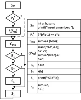
Program I, generating prime numbers smaller than , is used as an example to demonstrate how the proposed method works.
; ; ; ; ; ; ;
Fig. 9. Parsed CFG of Program I = (C ; (V; E)), where
C = S , V = fS ; S ; S ; B ; B ; g, and E =
(S ; B ); (B ; B ) ; (B ; ) ;(B ; S ) ; (B ; S ) ; (S ; S ); (S ; B ) .
; ;
We parse Program I and derive its CFG , as
illustrated in Fig. 9.
B. Obfuscation
We apply two control-flow obfuscating transformations: 1) the basic block fission obfuscation [6] and 2) the branch inser-tion transformainser-tion [9] in the example
1) Apply the Specified Basic Block Fission Obfuscation :
• Running
In this example, is
and is
Since splitting does not contribute to the range but increases the node count , becomes 5/11.
• Running :
We choose as . Inserting only
increases , so becomes 5/12. • Running
Fig. 10. Program II: the obfuscated result of Program I after applyingT .
We choose 3 for , which only works
with an integer . Since and increase, raises from 5/12 to 9/17.
• Running
We choose 2 2as .
After applying and obtaining , the obfuscated program (Program II) is generated according to (see Fig. 10).
2) Apply the Specified Branch Insertion Transformation :
• Running
Here, we use the same and .
• Running
Fig. 11. Program III: the obfuscated result of Program I after applyingT .
We choose 2 2as . inserts one
more code block, thus makng increase by one. is increased by one as well. Now, decreases to 6/13.
• Running :
Here, is generated by inserting dummy instructions.
Since contributes nothing to and , remains
unchanged.
• Running :
We choose as and insert the block
into the loop. Now, and are both increased and changes from 6/13 to 7/15.
Now, we regenerate the obfuscated program (Program III) ac-cording to (see Fig. 11).
C. Evaluation
Comparing , , and , the common subgraphs
of , , and have identical edges ,
, , , . We have
. Since the number of edges in , , and are 6, 12, and 10,
the distances between these graphs are and .
In , there are two branches and with range values 4 and 1. Hence, we obtain . In , the range values of
, , , and are 4, 5, 1 and 1. So, we obtain
and . Similarly, in , the range values
of , , and are 1, 5, and 1. So we can obtain
and .
A positive potency value implies that achieves obscurity from the perspective of the ratio of and , while a neg-ative value indicates that contributes nothing to that ratio. With the distance computed by using the proposed MGE, we
can obtain two vectors and
to show the abilities against re-verse engineering provided by and . Since both distance and potency of are larger than those of . We conclude that provides the better robustness than . The space penalty
caused by can be estimated as where
results in no overheads, leads to , and
and lead to two s. The space penalty caused by
is , where and do not derives
any overheads, but and lead to and ,
respectively.
IX. CONCLUSION
We presented a framework for representing, evaluating, and analyzing control-flow obfuscating transformations. We showed that with a graph-based representation, many existing control-flow transformations can be represented as a composi-tion of atomic operators. We have also proposed a new metric for quantifying the effects of these transformations upon the program. Such a metric may help evaluate the robustness and costs of control-flow obfuscating transformations.
Nevertheless, if we consider the side effects of obfuscating a software program—code size will increase and execution per-formance will slow down—more studies will be needed on how to best compromise between security and performance over-heads. We hope that our formal model will provide a helpful framework for examining these tradeoffs in greater depth.
REFERENCES
[1] S. Subramanya and B. Yi, “Digital rights management,” IEEE
Poten-tials, vol. 25, no. 2, pp. 31–34, Mar./Apr. 2006.
[2] Y. Nishimoto, A. Baba, T. Kurioka, and S. Namba, “A digital rights management system for digital broadcasting based on home servers,”
IEEE Trans. Broadcast., vol. 52, no. 2, pp. 167–172, Jun. 2006.
[3] D. Aucsmith, “Tamper-resistant software: An implementation,” in
Proc. 1st Int. Workshop Informaiton Hiding, 1996, vol. 1174, pp.
317–333.
[4] T. Wilkinson, D. Hearn, and S. Wiseman, “Trustworthy access control with untrustworthy web servers,” in Proc. Computer Security
Applica-tions Conf., Jan. 1999, pp. 12–21.
[5] N. Komninos, B. Honary, and M. Darnell, “Security enhancements for A5/1 without loosing hardware efficiency in future mobile systems,” in Proc. 3rd Int. Conf. 3G Mobile Communication Technologies, 2002, pp. 324–328.
[6] T. Hou, H. Chen, and M. Tsai, “Three control flow obfuscation methods for Java software,” Proc. Inst. Elect. Eng. Softw., vol. 153, no. 2, pp. 80–80, Jan. 2006.
[7] M. D. Preda and R. Giacobazzi, “Control code obfuscation by abstract interpretation,” in Proc. 3rd IEEE Int. Conf. Software Engineering and
Formal Methods, 2005, pp. 301–310.
[8] D. Low, “Java control flow obfuscation,” M.Sc. dissertation, Univ. Auckland, Auckland, New Zealand, 1998.
[9] C. Collberg, C. Thomborson, and D. Low, “A taxonomy of obfuscating transformations,” Rep. no. 148, 1997, Univ. Auckland Tech. Rep.. [10] C. Collberg and C. Thomborson, “Watermarking, tamper-proofing, and
obfuscation—Tools for software protection,” IEEE Trans. Softw. Eng., vol. 28, no. 8, pp. 735–746, Aug. 2002.
[11] J. Memon, S. u. Arfeen, A. Mughal, and F. Memon, “Preventing reverse engineering threat in Java using byte code obfuscation techniques,” in
Proc. Int. Conf. Emerging Technologies, 2006, pp. 689–694.
[12] C. Wang, J. Davidson, J. Hill, and J. Knight, “Protection of software-based survivability mechanisms,” Foundations Intrus. Tolerant Syst., pp. 273–282, 2003.
[13] T. Toyofuku, T. Tabata, and K. Sakurai, “Program obfuscation scheme using random numbers to complicate control flow,” Jan. 2005, IEIC Tech. Rep.
[14] T. László and A. Kiss, “Obfuscating C++ programs via control flow flattening,” Annales Universitatis Scientiarum de Rolando Eötvös
Nominatae—Sectio Computatorica, pp. 15–15, May 2008.
[15] J. Ge, S. Chaudhuri, and A. Tyagi, “Control flow based obfuscation,” in
Proc. 5th ACM Workshop on Digital Rights Management, Nov. 2005,
pp. 83–92.
[16] I. V. Popov, S. K. Debray, and G. R. Andrews, “Binary obfuscation using signals,” in Proc. 16th USENIX Security Symp., 2007, pp. 275–290.
[17] B. A. Cota and R. G. Sargent, “Automatic Lookahead computation for conservative distributed simulation,” CASE Center Tech. Rep. 8916, 1989.
[18] B. Cota, D. Fritz, and R. Sargent, “Control flow graphs as a represen-tation language,” in Proc. Simulation Conf., 1994, pp. 555–559. [19] “Chilling effects clearinghourse.” Dec. 12, 2008. [Online]. Available:
http://www.chillingeffects.org.
[20] H. Bunke and K. Shearer, A Graph Distance Metric Based on the
Max-imal Common Subgraph, vol. 19, no. 3-4, pp. 255–259, Mar. 1998.
[21] W. Wallis, P. Shoubridge, M. Kraetz, and D. Ray, “Graph distances using graph union,” Pattern Recogn. Lett., Jan. 2001.
[22] H. Zuse, Software Complexity: Measures and Methods. Hawthorne, NJ: Walter de Gruyter Co., 1991.
Hsin-Yi Tsai received the B.S. and M.S. degrees in electrical and control engi-neering from the National Chiao-Tung University, Taiwan, in 2007, where she is currently pursuing the Ph.D. degree in electrical and control engineering.
Her research interests include wireless security, DRM protection, and security analysis.
Ms. Tsai is a member of the Phi Tau Phi Society since 2007.
Yu-Lun Huang received the B.S. and Ph.D. degrees in computer science and information engineering from the National Chiao-Tung University, Taiwan, in 1995 and 2001, respectively.
Currently, she is an Assistant Professor in Department of Electrical and Con-trol Engineering of National Chiao-Tung University. Her research interests in-clude wireless security, secure testbed design, embedded software, embedded operating systems, network security, secure payment systems, VoIP, and QoS.
Dr. Huang has been a member of the Phi Tau Phi Society since 1995.
David Wagner is an Associate Professor in the Computer Science Division at the University of California at Berkeley, working in the areas of computer secu-rity and electronic voting. He has studied the secusecu-rity of cell-phone standards, 802.11 wireless networks, electronic voting systems, and other widely deployed systems, and is active in the areas of software security and systems security.
Prof. Wagner is a past CRA Digital Government Fellow and Alfred P. Sloan Research Fellow. He received an Honorable Mention in the ACM Doctoral Dis-sertation Award competition for his Ph.D. work.