國
立
交
通
大
學
多媒體工程研究所
碩
士
論
文
由三維模型產生穩固樂高模型之研究
A Study on the Stable LEGO Sculpture Generation
研 究 生:洪振耀
指導教授:施仁忠 教授
魏德樂 教授
由三維模型產生穩固樂高模型之研究
A Study on the Stable LEGO Sculpture Generation
研 究 生:洪振耀 Student:Jhen-Yao Hong
指導教授:施仁忠 Advisor:Prof. Zen-Chung Shih
魏德樂
Prof. Der-Lor Way
國 立 交 通 大 學
多 媒 體 工 程 研 究 所
碩 士 論 文
A Thesis
Submitted to Institute of MultimediaEngineering College of Computer Science
National Chiao Tung University in partial Fulfillment of the Requirements
for the Degree of Master
in
Multimedia Engineering August 2014
Hsinchu, Taiwan, Republic of China
i
由三維模型產生穩固樂高模型之研究
研究生: 洪振耀
指導教授
:施仁忠 教授
魏德樂 教授
國立交通大學多媒體工程研究所
摘 要
樂高積木是一項深受人們喜愛的玩具,在展覽裡可以欣賞到特殊、壯觀的樂 高作品,也有人以樂高為主題拍攝電影,。但是,對於初學者而言,要建構出一 個好的樂高模型並不容易,即使是熟練的專家同樣需要大量的時間才能拼出穩固 的模型。因此,我們提出了一個系統,使用者只需將 closed polygonal model 輸入 我們的系統中,系統會判斷 polygon 與 voxel 的相交情形,將 polygonal model 轉 換成 volumetric model,並透過減少內部 voxel 的方式調整模型的重心,最後針對 每塊積木的連結率以及積木成本做最佳化的處理,產生樂高積木每一層的結構圖。 使用者即可依照結構圖輕鬆的建出樂高模型。ii
A Study on the Stable LEGO Sculpture Generation
Student: Jhen-Yao Hong
Advisor: Prof. Zen-Chung Shih
Prof. Der-Lor Way
Institute of Multimedia Engineering
National Chiao-Tung University
ABSTRACT
LEGO is a popular toy all over the world. The LEGO sculptures have been applied in lots of occasions, such as an exhibition and a movie. However, building a stable sculpture is difficult for novices. Even a well-experienced user also need to spend much time to construct it. This thesis presents a system to build a LEGO sculpture easier. Given a closed polygonal model as the input, our system transforms this model to a volumetric model first. Secondly, by removing proper inner voxels, the model’s center of mass is adjusted to an appropriate position to make the model stand stably. Finally, the greedy merge algorithm builds the structures of a sculpture by optimize the trade-off between the connection and brick cost of each bricks. Consequently, users can build a stable and low-cost LEGO sculptures by following the assembly instructions.
iii
Acknowledgements
First of all, I would like to express my sincere gratitude to my advisors, Prof. Zen-Chung Shih and Prof. Der-Lor Way for their guidance and patience. Without their encouragement, I would not complete this thesis. Thanks also to all the members in Computer Graphics and Virtual Reality Laboratory for their reinforcements and suggestions. Thanks for my roommates Nien Hsieh, Che Chen and Pin- Jyun Liu who accompany me in the two year and give me suggestions when I am in confusion. Thanks for Yi-Ling Chiu and Mu-En Cheng help me to correct my paper. Thanks for those people who have supported me during these months. Finally, I want to dedicate the achievement of this work to my family.
iv
Contents
ABSTRACT(in Chinese) ... i ABSTRACT(in English) ... ii Acknowledgements ……….III Contents ... iv List of Figures ... vList of Tables ... vii
Chapter 1 Introduction ... 1
1.1 Motivation and System Design ... 2
1.2 Thesis Organization ... 3
Chapter 2 Related Works ... 4
2.1 Voxelization ... 4
2.2 Stable Structure of LEGO Sculptures ... 5
2.3 Legolization ... 8
Chapter 3 Algorithm ... 9
3.1 Voxelization ... 10
3.2 Center of Mass Adjustment ... 13
3.2.1 Erasable Voxel ... 13
3.2.2 Safe Region ... 14
3.2.3 Adjusting Center of Mass... 17
3.3 LEGO Brick Merging ... 19
3.3.1 Voxel Selection ... 20
3.3.2 A Set of Valid Legal Bricks ... 22
3.3.3 Merging LEGO Bricks ... 23
Chapter 4 Implementation and Results ... 27
4.1 Implementation ... 27
4.2 Results ... 30
4.3 Limitation ... 42
Chapter 5 Conclusion and future work ... 44
v
List of Figures
Figure 1.1: The Images of LEGO exhibitions and the movie “THE LEGO MOVIE”
[16] ……...1
Figure 2.1: The illustrations of (a)(b) directions and vertical boundaries, (c) T-shaped boundary, and (d) centered the boundary of bricks ... 6
Figure 2.2: The left image shows the puzzle pieces Song et al. created [8]. The right one shows the common bricks ... 7
Figure 2.3: The illustrations [4] of (a) stud-up sculpture, and (b) stud-out sculpture. .. 8
Figure 3.1: The flow of our proposed system architecture ... 10
Figure 3.2: The illustration of the 13 separating axes. ... 11
Figure 3.3: The examples of the projections of V and T onto a is disjoint or not ... 12
Figure 3.4: (a) The shell in the 8th layer of the voxelized bunny model in (b). The thickness of the shell is 3-unit-birck. ... 13
Figure 3.5: (a) The six direction of a voxel V. (b) The examples of erasable voxels . 14 Figure 3.6: The top view of voxels and the convex hull in the bottom layer..... 16
Figure 3.7: The voxelized bunny model. 𝑐 ⊥ is the projection of center of mass onto the ground plane. The blue convex is the safe region of the bunny model. ... 17
Figure 3.8: We separate the model into two half spaces based on 𝑐 ∗. ... 18
Figure 3.9: The model (a) before and (b) after adjust center of mass. 𝑐 ⊥ is moved to the safe region after adjusting it. (c) and (d) the inner structure of the model ... 19
Figure 3.10: The legal bricks ... 20
Figure 3.11: (a) A shell is composed of 1*1 bricks. (b) Using proper bricks makes the shell stable and buildable. ... 21
Figure 3.12: Red voxel: the number of neighbors are 2. Yellow voxels: the number of neighbors are 3. The voxels with few neighbors usually exist on the shell. ... 21
Figure 3.13: (a) The examples of putting a 2*4 brick on the chosen voxel laterally. (b) The examples of putting a 2*4 brick on the chosen voxel longitudinally. ... 22
Figure 3.14: The example of (a)(b) valid legal bricks and (c) invalid bricks. ... 23
Figure 3.15: Two bricks are connected when they overlap. ... 23
Figure 3.16: The example of a brick without any connection.. ... 25
vi
and (f) are the assembly instructions of them respectively. ... 26
Figure 4.1: (a) Coca. (b) Bunny. (c) Yoshi. (d) Dragon models.... 27
Figure 4.2: The structures of 7th and 8th layers of the bunny sculpture. The thickness is 3-unit-brick. ... 28
Figure 4.3: (a) and (b) show the structures of the 8th and 9th layers of the voxelized coca model. The shell’s thickness of the model is a 2-unit-brick length... 29
Figure 4.4: The content of a LEGO box. It shows the quantities of each brick. ... 30
Figure 4.5: (a) The oblique bunny model. (b) The voxelized model. (c) The LEGO
sculpture whose ear is pendent. ... 311
Figure 4.6: (a) The voxels in the lowest layer. (b) The structure of the lowest layer. (c)
Real LEGO bricks built base on (b). (d) The final sculpture. ... 311
Figure 4.7: (a) to (d) are the 14th, 15th, 17th and 18th layers of the oblique bunny sculpture. ... 322
Figure 4.8: The polygonal bunny model is transformed to a LEGO sculpture... 333
Figure 4.9: (a) to (d) show the 9th to 12th layers of the bunny sculpture and their assembly instructions respectively. Its thickness is 3-unit-brick. ... 333
Figure 4.10: (a)(b) The polygonal and voxelized model of dragon respectively. (c)(d)
The sculpture with 22 layers is built practically (e) The structure of the 1st layer. It is separated into two parts. (f) The structure of the 6th Layer. ... 355
Figure 4.11: (a) The Yoshi polygonal model. (b) The Voxelized model. (c) The Yoshi
sculpture. (d) There only one leg touch the floor. ... 366
Figure 4.12: (a) The polygonal model of coca. (b) The sculpture with 33 layers. (c) The
sculpture with 22 layers. ... 377
Figure 4.13: The layer’s structures of the coca sculpture. ... 388
Figure 4.14: The layer’s structures of the coca sculpture. The order is from (a) to (f).
(d) shows how the large brick crosses the gap. ... 399
Figure 4.15: The structures with different α-value. Structures with greater α-value use
more larger bricks. ... 40
Figure 4.16: The structures of the dragon and the coca model. ...42 Figure 4.17: The left image shows that there are some bricks cannot be built. The bricks
are connected by the above bricks in the right images. ... 42
Figure 4.18: (a) and (b) shows the projection of center of mass before and after
adjusting the center of mass. ………43
vii
List of Tables
Table 4.1: The cost of each brick type. ……….30
Table 4.2: The executing time of removing voxels….……….41
Table 4.3: The averages of the executing time and the numbers of generation bricks for
1
Chapter 1
Introduction
LEGO is a popular toy all over the world. People can show their imagination by building a wonderful work with Lego bricks. As shown in Figure 1.1, LEGO sculptures have been applied in lots of occasions. We can appreciate magnificent works in LEGO exhibitions. Besides, some movies are created based on these LEGO sculptures [16]. LEGO was originated in 1940s [18], despite it has been 60 years, it was still voted as the favorite toy in 2008 [17]. As mentioned, LEGO is popular and close to life. There are many different kinds of bricks. The specialized LEGO pieces allow orthogonal connections [5], and the “nanoblock”, which was created by a Japanese company in 2008 [15], can build mini size sculptures. The brick we use is the common one. Its width and length of a unit LEGO brick is 8 mm, and height is 9.6mm. There are various types of bricks, and we would like to build a stable sculpture by assembling them.
Figure 1.1: The left image is the publicity of LEGO exhibitions. The right image is
2
Some previous papers focus on optimizing the structure of a LEGO sculpture. A few researches discuss about the center of mass of a sculpture. Most of the models they used can stand originally. However, if we tilt a model, it might be not able to stand anymore, even its structure is firm. In other words, it is necessary to consider center of mass when building a stable LEGO sculpture. Moreover, users can build a sculpture with different poses by adjusting the center of mass, so that the selection of a polygonal model becomes more flexible.
1.1 Motivation and System Design
Building a stable sculpture is not easy for a novice, even a well-experienced user also needs lots of time to build it. Therefore, “How to build a wonderful sculpture” becomes a challenge for the LEGO Company. They brought up this question in 1998 [3]. Up to now, this question is still be researched. Appearance and stability are the two important elements for judging a good sculpture. If the sculpture is not stable, it might be broken easily. More serious is that the sculpture is not able to stand stably. Therefore, there are lots of research to discuss how to build a sculpture with stable structure. [3][6][13], but most of these researches use optimal method which spend too much time, and none of them build the sculpture practically to ensure their correctness.
Synthetically, creating a system that makes the process of building a LEGO sculpture easier is necessary for people. It is the main purpose of this paper. Furthermore, we increase the flexibility when choosing a polygonal model. In our proposed system, users input a closed polygonal model first, then they can scale or rotate the model. After that, the system transforms the polygonal model to a set of voxels by testing whether voxels and polygons overlap, and recording the center
3
position of voxels. Next, to adjust the center of mass of a model to a suitable position, we remove proper inner voxels. Finally, the system apply a greedy merge algorithm for this voxelized model. We merge voxels into a set of bricks to get stable structures, which are outputted as the assembly instructions. Users can build a sculpture by following the instructions.
Our contribution is to present a system which can adjust the center of mass of a model dynamically, making the chosen of model more flexible. The trade-off between the connection and brick cost is dealt with in our greedy merge algorithm. So the result balances the stability and the cost of a sculpture. As long as the structure satisfies the conditions we set, the sculpture is strong enough to stand stably. Therefore, we do not need to search the most optimal structure. It speed up the process of optimization.
1.2 Thesis Organization
This thesis is organized as follows: In chapter 2, we review the related work about voxelization, the stability of a LEGO sculpture, and legolization. Then, we will show the flow of our proposed system and describe the detail of each process in chapter 3. Chapter 4 shows our implementation and result. Conclusion and future work are discussed in chapter 5.
4
Chapter 2
Related Works
2.1 Voxelization
A LEGO sculpture is assembled by lots of bricks. Therefore, before analyzing a LEGO structure, we should transform the polygonal model to voxels. We denote this process as “voxeliztion”, which is a mature topic. Silva et al. [8] voxelized a polygonal model to a set of colored voxels and showed them on a screen. They subdivided a triangle to smaller sub-triangles in order to guarantee that a triangle only intersects with one voxel. Therefore, the color of a voxel can be determined by the triangle which it intersects with. However, the color of a voxel is not necessary for our system so we do not need to subdivide triangles. Voorhies [14] tested the intersection between a cube and a triangle to voxelize a polygonal model. He reduced the number of voxels by doing a series of acceptance/rejection tests to speed up the intersection test. Green and Hatch [4] improved the efficiency of Voorhies’ approach. They tested whether the point is in the skewed rhombic dodecahedron in acceptance/rejection tests to make the test more robust. In addition, they made the test be able to deal with arbitrary triangles. We use
Akenine-Möller’ method [1] to test intersections among triangles and cubes based on separating axis theorem (SAT). This approach tests whether the projections of a triangle and a cube onto an axis are overlap or not. It is 2.3 times faster than Green and Hatch’s approach.
5
2.2 Stable Structure of LEGO Sculptures
Several researches are proposed after the LEGO Company presents the question “how to build a sculpture fast”. Gower et al. [3] proposed six heuristic rules, which are shown as follows:
1. High percentage area of each brick should be covered. It can increase the stability of the LEGO sculpture and the connection of each brick.
2. Larger bricks are better. Large bricks are not only increase the connection, but also decrease the sum of brick number.
3. The direction of each consecutive layer should not be the same. It increases the stability of the full sculpture, and decrease the chance of local connection (Figure 2.1 (a) (b)).
4. The vertical boundary (Figure 2.1 (a) (b)) must be covered by the above and below layer. It can help to avoid local connection and unconnected sculpture.
5. If two bricks form T-shaped boundary with its neighborhood, its middle will be at the boundary of its neighborhood (Figure 2.1 (c)).
6. If a brick covers a vertical boundary in previous layer, it should match the boundary (Figure 2.1 (d)).
6
Figure 2.1: The illustrations [9]. (a)(b) The arrows are the directions of bricks. The
black boundaries of the two bricks are the vertical boundary. (c) Both of the two red bricks form a T-shaped boundary with their neighborhood (the blue and yellow bricks). The middle of the red bricks are match the boundaries of their neighbors. (d) When the center of the red brick match the boundary of the bricks in previous layer, it
reinforce the stability.
The direction is the longer side of a brick. Vertical boundary is the boundary of a brick looked in top view. Gower used these heuristics to design a penalty function and calculated the minimum penalty value with simulated annealing algorithm. The more heuristics this model satisfies, the less the penalty value is. In other words, the sculpture is more stable. However, it spends too much time and they never built a LEGO sculpture practically. Petrovic [6] proposed a gene algorithm to replace simulated annealing algorithm. But they still did not build any sculpture in reality.
7
Gower’s heuristics [3], they designed a cost function to determine whether to merge a voxel into a brick. Although this method is not a traditional optimal algorithm, it still needs lots of time to check the rules of heuristics.
Another methods to increase the stability of a sculpture is interlocking. Song et al. [10] was inspired by the interlocking puzzle, whose puzzles can be locked by another puzzles. They used a recursive method to design a puzzle one by one from a voxelized model and ensured that the newest puzzle can lock others. Their approach indeed creates a stable sculpture, but the shape of the puzzles designed by them is various, as shown in Figure 2.2. Thus, this method cannot be used in LEGO sculpture. Stava et al. [9] proposed a stress relief method. The method we use to adjust center of mass is similar to theirs. They reduced the pressure of some frail parts by hollowing the inner areas. However, they still needed struts to reinforce the stability of models. In our approach, we remove inner voxels to adjust the center of mass of the whole model instead of the frail parts. Therefore, if the center of mass is moved to the ideal position. The model can stand stably without any struts.
Figure 2.2: The left image shows the puzzle pieces Song et al. created [8]. The right
8
2.3 Legolization
Silva et al. [8] provided a process of subdividing triangles and voxelization by using GPU. They transformed a polygon model to a LEGO sculpture efficiently. However, this technique just showed the models on screen after legolizating. They did not discuss the stability of a sculpture and build it practically. Lambrecht [5] categorized LEGO sculpture into two types: stud-up and stud-out model, as shown in Figure 2.3. They focused on the stud-out model, whose bricks allowed orthogonal connections. Despite the bricks make the sculptures more realistic, they are not used widely.
Figure 2.3: The illustrations [5] of (a) stud-up sculpture, and (b) stud-out sculpture.
Testuz et al. [12] replaced graphic algorithm with heuristic optimization algorithms. Using their algorithm, the whole process does not need to consider all heuristics, because most heuristics are related to the connections among bricks. The more connection of a brick has, the more stable the sculpture is. Calculating the connection of a brick and optimizing LEGO structures by graphic algorithm can enhance the efficiency of computing a stable structure layer-by-layer. We propose our improvement to extend to hollowing and center of mass adjusted models.
9
Chapter 3
Algorithm
The goal of this research is to build a LEGO sculpture easier. In this chapter, we describe the process of the assembly instructions generation. By following the instructions of each layer, users can build a stable and low-cost LEGO sculpture. Figure 3.1 explains the flow of our proposed system. The final output present the assembly instructions of each layer. These instructions assist people to build a LEGO sculpture of an input model in any pose. Furthermore, the constructed LEGO sculpture can always stand at the ground plane stably.
The input of our proposed system is a closed polygonal model. Users can rotate or scale the model arbitrary. The first step is voxelization. The input model is voxelized into a volumetric model. Secondly, in order to make the LEGO sculpture stand stably, we need to adjust the center of mass (CoM) by removing proper inner voxels of the LEGO sculpture. Finally, we optimize the trade-off between the connection and brick cost to construct a suitable structure of each layer. The connection influences the stability of a sculpture and the brick cost is related to the usage rate of different bricks.
The rest of this chapter is organized as follows. In section 3.1 we describe how to test the intersection between a voxel and a triangle by Akenine-Möller’ approach [1]. We define “erasable voxel” and “safe region”, and explain the process of adjusting center of mass in section 3.2. And the section 3.3 discuss about the greedy merge algorithm which deals with the trade-off between the connection and each brick cost
10
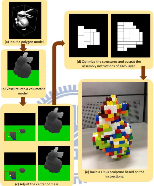
Figure 3.1: The flow of our proposed system architecture. (a) The input model and its
axis-aligned bounding box. (b) The voxelized model. (c) It shows the center of mass before and after adjusting center of mass. (d) The 2nd and 3rd layers’ assembly
instructions of the oblique bunny. (e) The bunny LEGO sculpture.
3.1 Voxelization
11
We apply Akenine-Möller’s approach [1] to detect the intersection among voxels and triangles. Based on the separating axis theorem (SAT), if there exists an axis onto which the projections of a voxel V and a triangle T do not overlap, V and T do not overlap. The axes onto which V and T project are separating axes. If V and T are disjoint, there is a separating plane between them. And the axes is orthogonal to a separating plane. We test 13 separating axes as shown in Figure 3.2:
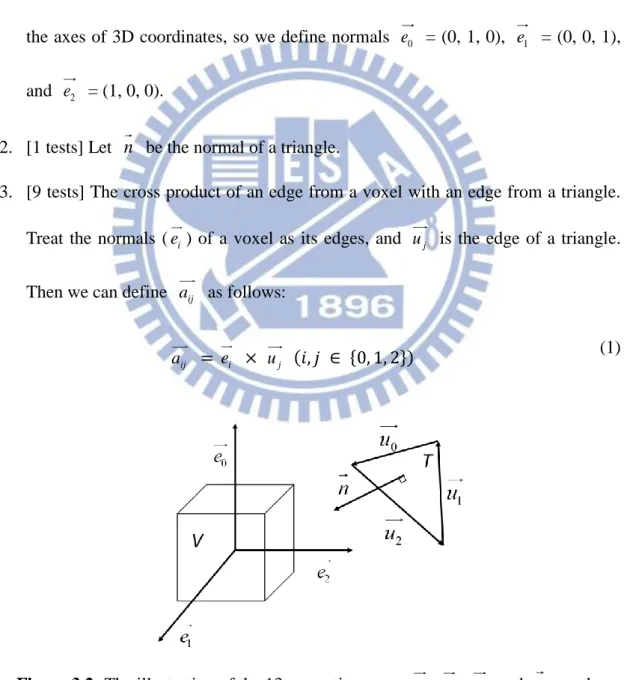
1. [3 tests] Let e , 0 e , and 1 e2 are the normals of a voxel. Voxels always align with the axes of 3D coordinates, so we define normals e = (0, 1, 0), 0 e1 = (0, 0, 1), and e = (1, 0, 0). 2
2. [1 tests] Let n be the normal of a triangle.
3. [9 tests] The cross product of an edge from a voxel with an edge from a triangle. Treat the normals (e ) of a voxel as its edges, and i uj is the edge of a triangle. Then we can define aij as follows:
ij
a = ei × uj (𝑖, 𝑗 ∈ {0, 1, 2})
(1)
Figure 3.2: The illustration of the 13 separating axes. e , 0 e , 1 e , and 2 n are the
12
To simplify the test, we move the triangle first, so that the voxel is centered on the origin. Let a = (𝑎𝑥, 𝑎𝑦, 𝑎𝑧) stands for one of the 13 separating axes. The process of intersection test is as follows:
1. Project triangle vertices (𝑣0 to 𝑣2) onto a.
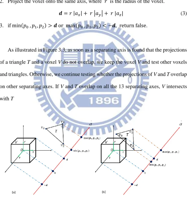
𝒑𝑖 = a ∙ 𝑣𝑖 (𝑖 ∈ {0, 1, 2}) (2) 2. Project the voxel onto the same axis, where 𝑟 is the radius of the voxel.
𝒅 = 𝑟 |𝑎𝑥| + 𝑟 |𝑎𝑦| + 𝑟 |𝑎𝑧| (3) 3. if min(𝑝0 , 𝑝1, 𝑝2) > 𝒅 or max(𝑝0 , 𝑝1, 𝑝2) < −𝒅, return false.
As illustrated in Figure 3.3, as soon as a separating axis is found that the projections of a triangle T and a voxel V do not overlap, we keep the voxel V and test other voxels and triangles. Otherwise, we continue testing whether the projections of V and T overlap on other separating axes. If V and T overlap on all the 13 separating axes, V intersects with T
Figure 3.3: (a) The projections of V and T onto a do not overlap, so V and T are disjoint. (b) The projections of V and T are overlap on this separating axis. We test
13
3.2 Center of Mass Adjustment
A model can stand stably if the projection of the center of mass is located on the suitable area, which is denoted as the “safe region” of the sculpture. However, for an arbitrary solid model, the center of mass may not lie in the safe region. Thus, we remove voxels to adjust the center of mass. In addition, to avoid destroying the appearance of a model, only the inner voxels can be removed.
3.2.1 Erasable Voxel
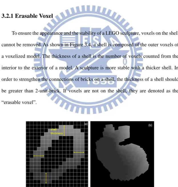
To ensure the appearance and the stability of a LEGO sculpture, voxels on the shell cannot be removed. As shown in Figure 3.4, a shell is composed of the outer voxels of a voxelized model. The thickness of a shell is the number of voxels counted from the interior to the exterior of a model. A sculpture is more stable with a thicker shell. In order to strengthen the connections of bricks on a shell, the thickness of a shell should be greater than 2-unit-brick. If voxels are not on the shell, they are denoted as the “erasable voxel”.
Figure 3.4: (a) The shell in the 8th layer of the voxelized bunny model in (b). The thickness of the shell is 3-unit-birck.
14
The method of determining an erasable voxel is to count the number of its surrounded voxels. If the surrounded voxels of the voxel V is over the shell’s thickness in all the six directions, V is an “erasable voxel”, as displayed in Figure 3.5(a). Figure 3.5(b) illustrates the example of erasable voxels. Voxel A is not an erasable voxel because its number of surrounded voxels in right and behind side is less than the shell’s thickness. In contrast, Voxel B is an erasable voxel.
Figure 3.5: (a) The six direction of a voxel V. (b) The shell’s thickness is 2-unit-birck.
For voxel A, the number of surrounded voxels is 0 in the right side, and it is 1 in the behind side. For voxel B, the number of surrounded voxels is over 2 in all directions.
3.2.2 Safe Region
A safe region means the convex hull of the area where voxels in the lowest layer contacting the ground plane. Based on Prevost’s approach [7], the model can stand stably without any struts when the projection of center of mass onto the ground plane
15
lies in the safe region. We apply Andrew's Monotone Chain convex hull algorithm [2]
to build the convex hull. The pseudo codes are presented in Pseudocode 1 and 2.
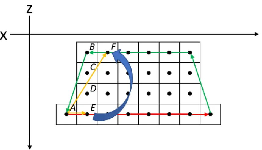
In this algorithm, we build a lower hull and an upper hull separately, and concatenate them to form a complete convex hull. Both of the lower hull and upper hull connect to the center of voxels counterclockwise, but a lower hull connects voxels form the leftmost to the rightmost, and the other is reverse, as shown in Figure 3.6.
16
Figure 3.6: The top view of voxels in the bottom layer. The green line is the upper
hull and the red line is the lower hull. If it is clockwise from AE to AF , A, E and F are the vertices of the convex hull.
The processes of building a lower and upper hull are the same. We use a list (L and
U, as shown in pseudocode 1) to record the vertices of them. As described at line 7 and
14 in pseudocode 1, the last two vertices in the list and P[i] are used to determine whether the vertices in the list are real vertices or not. For example, as displayed in figure 3.6, voxel A and E are vertices of the lower hull and recorded in list L, and voxel
F is the current P[i]. If the cross product of AE and AF is lower than 0, which means they are clockwise, we remove E from L, and then compute the cross product for the current last two vertices and F iteratively. In contrast, F is the new vertex of the convex hull, so we insert B into L. Figure 3.7 displays the safe region built by this algorithm and the center of mass’s projection (𝑐⊥, as shown in Figure 3.7) that is not in the safe region.
17
Figure 3.7: The voxelized bunny model. The blue convex is the safe region of the
bunny model. 𝑐⊥ is the projection of center of mass onto the ground plane.
3.2.3 Adjusting Center of Mass
According to Prevost’ approach [7]. If the distance from a voxel to center of mass is greater, removing the voxel can adjust center of mass much closer to the safe region. Therefore, we sort the voxels in decreasing order by the distance and remove the voxels. We calculate the distance as follows:
𝑑𝑖 = (𝑐𝑖− 𝑐∗) ∙ (𝑐 − 𝑐∗) (4) , where 𝑐𝑖 is the center of a voxel. 𝑐∗ is the center of the safe region and its height equals to the center of mass. 𝑐∗ is also treated as the ideal center of mass. 𝑐 is the center of mass’s position, and we get it by Eg. 5:
𝑐 = ∑𝑛𝑖=0𝑐𝑖
𝑛 (5)
, where 𝑛 is the total number of voxels in a model. As shown in Figure 3.8, a model is separated into two half spaces by a plane which is perpendicular to the ground plane and passes through 𝑐∗. Removing the voxels located in the half space, which contains
18
the center of mass, can make 𝑐 closer to 𝑐∗. In contrast, removing the voxels in the other half space makes 𝑐 further away from 𝑐∗. Consequently, voxels can be removed if they are in the same half space with center of mass. We remove voxels whose distances are greater than 0.
Figure 3.8: We separate the model into two half spaces based on the ideal center of
mass (𝑐∗). When 𝑐 and 𝑐
𝑖 are in the same half space, removing 𝑐𝑖 can make 𝑐 closer to 𝑐∗.
The effect of adjusting center of mass is presented in Figure 3.9. 𝑐⊥ is moved into the safe region after adjusting center of mass, so the model can stand stably after built in reality. Although a model is stable while the center of mass lies in the safe region, we continue removing erasable voxels to decrease the number of voxels as less as
19
possible. At last, we will remove all voxels which are in the same half space with center of mass.
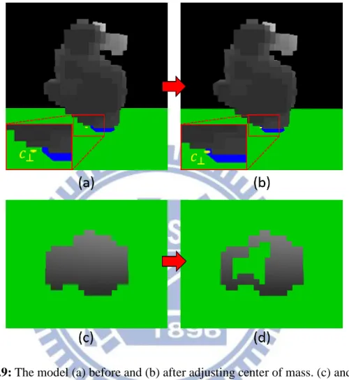
Figure 3.9: The model (a) before and (b) after adjusting center of mass. (c) and (d)
Compare the inner structure of the model before and after adjusting center of mass.
3.3 LEGO Brick Merging
To build a stable LEGO sculpture more easily in reality, we need the assembly instructions of each layer. Because the types of LEGO bricks are various, it costs too much time to test all types of bricks and choose the proper one. Therefore, we constrain the usable types, as shown in Figure 3.10, and denote them as “legal brick”.
20
Figure 3.10: The legal bricks [12].
We construct the instructions layer-by-layer by a greedy merge algorithm, which merges voxels into a legal brick with highest value. The process of optimizing an assembly instruction is presented in Pseudocode 3. We describe the details of each step in the following sub-sections:
3.3.1 Voxel Selection
The shell of a LEGO sculpture is often difficult to build because there are too many 1*1 bricks. It causes weak connection of the bricks on the shell, as displayed in Figure 3.11. Thus, we raise the probability of being selected for the voxels which are on a shell in order to merge them into bricks first. The probability is determined by the number of a voxel’s neighbors and computed as Eg. 6,
probability = {1 / exp(𝑛𝑢𝑚) , 𝑜𝑡ℎ𝑒𝑟𝑤𝑖𝑠𝑒1, 𝑖𝑓 𝑛𝑢𝑚 ≤ 3 (6) , where num is the number of neighbors. We make the voxels with less neighbors are
21
chosen more easily because they are usually on the shell, as shown in Figure 3.12.
Figure 3.11: (a) A shell is composed of 1*1 bricks. It cannot be built in reality
because of the weak connection of bricks. (b) Using proper bricks makes the shell stable and buildable.
Figure 3.12: Ignore the vertical neighbors. Red voxel: the number of neighbors is 2.
Yellow voxels: the number of neighbors is 3. The voxels with few neighbors usually exist on the shell.
22
3.3.2 A Set of Valid Legal Bricks
We combine the chosen voxel and its neighbors to form a legal brick. A brick can be put laterally or longitudinally, which means that a brick is able to involve in the chosen voxel with different positions. For example, there exists 16 different selections for a 2*4 brick as presented in Figure 3.13.
Figure 3.13: The yellow voxel is a chosen voxel. The green brick is a 2*4 brick. (a)
Two examples of putting a 2*4 brick on the chosen voxel laterally. (b) Two examples of putting a 2*4 brick on the chosen voxel longitudinally.
We test all the selections of each legal brick to confirm whether they are valid or not. As illustrated in Figure 3.14, a brick becomes valid if all the voxels in this brick exist; otherwise, the brick is invalid. Therefore, each brick’s type can produce several “valid legal bricks”. We compute the connections and brick costs of all the valid legal bricks, and merge the chosen voxel and its neighbors to the optimal one.
23
Figure 3.14: The chosen voxel (yellow) and its neighbors is merged into a 2*4 brick
(red). We put the brick in different positions. The positions of a brick in (a) and (b) are valid legal bricks. (c) A 2*4 brick with unsuitable position is invalid because it does
not contains 8 voxels
3.3.3 Merging LEGO Bricks
In order to build a stable and low-cost sculpture, we need to consider the vertical connections and brick costs of all the valid legal bricks in the greedy merge algorithm. As shown in Figure 3.15, brick A connects with brick B if they overlap in vertical.
Figure 3.15: Two bricks are connected when they overlap.
The connection of a brick means how many bricks it connects with. It influences the stability of a LEGO sculpture because bricks do not drop easily if they are connected by a lot of other bricks. A large brick has higher connection commonly. For example, a
24
2*4 brick can connect with 8 bricks at most, but a 1*4 brick only connect with 4 bricks. The brick cost is determined by the number of each brick’s type. Larger bricks are less in reality. Consequently, though the large bricks own higher connections, their brick costs are higher because of their rarity. We can reduce the usage rate of the large bricks to cost down. Our algorithm deals with the trade-off between connection and each brick cost, then selects a valid legal brick with highest value. The value of a valid legal brick is computed as Eg. 7,
𝑉𝑏 = 𝛼𝑐1− (1 − 𝛼)𝑐2 (7) , where 𝑐1 is the connection, and 𝑐2 is the cost of a brick’s type. We square the connection in order to reinforce its influence. 𝛼 is the weight of 𝑝1. Higher α-value can strengthen the connections of bricks. Otherwise, the structure with low α-value is frail, but the demands for rare bricks are decreased.
In some special cases, it is not enough to take care of only connections and brick costs when merging bricks. Therefore, we propose three exceptions and show them as follows:
(a) In the button layer. The bricks are as larger as possible. (b) If the brick does not connect with other bricks. 𝑉𝑏= −∞
(c) If the brick connects with other bricks and its center does not overlap the bricks it connect. 𝑉𝑏= ∞ + 𝑑𝑖𝑠𝑡, where 𝑑𝑖𝑠𝑡 is the minimal distance from the center of the brick to the centers of voxels it connects.
As displayed in Figure 3.16, 𝑑𝑖𝑠𝑡 is the distance between B1 and V2. Higher
distance means that B1 is a larger brick. We use larger bricks to avoid producing bricks
which are pendent. In Figure 3.18(a), B2 does not connect with other bricks, thus it
25
brick B1, as shown in Figure 3.18(b). After increase exceptions, the process of
calculating optimal brick value is presented in Peeudocode 4. Exception (a)(b)(c) are implemented at line 9, 11, and 14 respectively.
Figure 3.16: V1 and V2 are the voxels in the brick B3, which connects with brick B1.
26
These exceptions reduce the bricks which do not connect with other bricks. Figure 3.17 shows the parts of the bunny sculpture. Our system merges a 2*4 brick which crosses the gap, as displayed in Figure 3.17 (c), so the brick does not drop into the gap and it becomes a good base for the above bricks, as shown in Figure 3.17 (e).
Figure 3.17: (a) the 19th, (c) 20th, and (e) the 21th layers of the bunny sculpture. (b), (d) and (f) are the assembly instructions of them respectively. (c) The effect of the exceptions. It chooses larger brick in priority, so that the bricks in the 21th layer can be
27
Chapter 4
Implementation and Results
In this chapter, we present our implementation and results. The explanation of how to decide the brick costs is discussed in section 4.1. Moreover, there are two modes to remove inner voxels. In section 4.2, we shows our results and the structures with different parameters.
4.1 Implementation
The implementation was under the Intel Extreme CPU X9650 with 3.0 GHz and 4GB memory. The IDE is Microsoft Visual Studio 2012. All the polygonal models are acquired from Google 3D warehouse, as shown in Figure 4.1.
Figure 4.1: (a) Coca. (b) Bunny. (c) Yoshi. (d) Dragon models.
There are two modes to remove the inner voxels: hollowing mode and adjusting CoM mode. If the projection of center of mass is located on the safe region after voxelizing, we can use hollowing mode. Therefore, all the erasable voxels are removed, and the model can be built with fewer bricks. The sculpture turns into a stable status
28
when the thickness of the shell is higher than 3-unit-brick, as shown in Figure 4.2. On the other hand, while a model’s center of mass is not situated on the safe region, we use adjusting CoM mode. Under this circumstance, the model’s center of mass is moved into the safe region. However, not all the erasable voxels can be removed because the current center of mass will be further away from the safe region, after removing the inappropriate voxels. Figure 4.3 illustrates the effect on adjusting center of mass. The voxels in the green dash area cannot be removed because they are not in the same half space with center of mass. After adjusting the center of mass, we cannot use the hollowing mode for the same model.
Figure 4.2: The structures of 7th and 8th layers of the bunny sculpture. The thickness is 3-unit-brick.
29
Figure 4.3: (a) and (b) show the structures of the 8th and 9th layers of the voxelized coca model. The shell’s thickness of the model is a 2-unit-brick length.
In a LEGO box, there are several types of bricks with different quantities. Figure 4.4 presents the quantities of the brick types in a LEGO box. The less quantity of the brick type, the higher the brick cost is. Take red bricks as an example, 1*2 and 2*2 bricks are more than others, thus, we can use them more frequently. In contrast, there is only one 2*8 brick in this box, so we raise its cost to reduce the usage rate. The cost is the quotient of dividing 1*2 brick’s quantity by each brick type’s quantity, and then we modifying them by trail-and-error to get suitable costs. Most of the costs are based on their quantities except for the 1*1 brick, since it owns little connection. We raise its cost to avoid using it too often. Table 4.1 shows the actual costs of bricks in our system.
30
Figure 4.4: The content of a LEGO box. It shows the quantities of each brick type.
Brick type Number Cost Brick type Number Cost
1*1 132 20 2*2 136 2 1*2 224 1 2*3 36 6 1*3 36 6 2*4 39 10 1*4 26 10 2*6 3 70 1*6 10 15 2*8 2 100 1*8 6 30
Table 4.1: The cost of each brick type in a LEGO box.
4.2 Results
Our method is powerful and flexible. For example, the same bunny model can be rotated to a new pose that the tail is contacted the ground, as shown in Figure 4.5. Because the projection of the center of mass is not in the safe region, the adjusting CoM mode is applied to remove inner voxels. Figure 4.6 illustrates the structure of the lowest layer. The oblique bunny sculpture can stand stably even though only a few bricks touch to the ground. In Figure 4.7(b), we notice that although some bricks do not connect with below layer, they can be connected by the bricks in the above layer. Finally, users can still finish the bunny sculpture successfully, as shown in Figure 4.7.
31
Figure 4.5: (a) The oblique bunny model. (b) The voxelized model. (c) The LEGO
sculpture whose ear is pendent. The bricks in the bottom of the ear do not drop because they are connected by the bricks in the above layer.
Figure 4.6: (a) The voxels in the lowest layer. (b) The structure of the lowest layer.
32
Figure 4.7: (a) to (d) are the 14th, 15th, 17th and 18th layers of the oblique bunny sculpture. (a) and (b) show the right bricks cannot connect with the below layer. (c) and (d) display the ears of the bunny finally connecting the bunny’s body positively.
Figure 4.8 displays the bunny sculpture. Because the center of mass lies in the safe region, we use the hollowing mode to remove erasable voxels. Hence, the weight of the sculpture will be lighter than the solid one. Figure 4.9 shows some inner structures of the bunny sculpture and their assembly instructions. Our system can uses suitable bricks to cover the gaps among the bricks.
33
Figure 4.8: The polygonal bunny model is transformed to a LEGO sculpture with 19
layers.
Figure 4.9: (a) to (d) show the 9th to 12th layers of the bunny sculpture and their assembly instructions. Its thickness is 3-unit-brick.
34
Figure 4.10 presents the sculpture of the dragon. The bottom layer of the dragon model is separated into two parts, and will be assembled in the 6th layer. Figure 4.11 exhibits the sculpture of Yoshi. The Yoshi model is not stable because it only uses one leg to stand. After adjusting the center of mass, the sculpture can stand stably in real world.
Our system can produce sculptures with different resolutions, and users can choose a suitable one to create sculptures. The resolution of a LEGO sculpture is determined by the number of layers. Figure 4.12 shows the coca sculptures with 33 layers and 22 layers. For the same polygonal model, the more layers the sculpture has, the more precise the resolution gets. The partial inner structures of the coca sculpture with 22 layers are presented in Figure 4.13 and 4.14. In Figure 4.14 (e), the yellow 2*8 brick crosses the gap, so users can finish the remaining layers.
35
Figure 4.10: (a)(b) The polygonal and voxelized model of dragon. (c)(d) The
sculpture with 22 layers is built practically and shown in different views. (e) The structure of the bottom layer. It is separated into two parts. (f) The structure of the 6th
36
Figure 4.11: (a) The Yoshi polygonal model. (b) The Voxelized model. (c) The Yoshi
sculpture. (d) The Yoshi sculpture use only one leg touching the floor.
37
Figure 4.12: (a) The polygonal model of coca. (b) The sculpture with 33 layers. (c)
The sculpture with 22 layers. The sculpture in (b) is larger and more delicate than the sculpture in (c).
38
Figure 4.13: The layer’s structures of the coca sculpture. The order is from (a) to (f).
39
Figure 4.14: The layer’s structures of the coca sculpture. The order is from (a) to (f).
40
In the process of merging bricks, users can modify the α-value based on their demand. The structures with different α-value are shown in Figure 4.15. The structure is assembled with lots of large bricks when α is equal to 1.0. On the other hand, if α is equal to 0.0, the structure uses 1*2 bricks too often. All the assembly instructions of our results are designed with α = 0.5.
Figure 4.15: The structures with different α-value. Structures with greater α-value use
more larger bricks.
The executing time of different models is shown in Table 4.2 and 4.3. Models with greater number of voxels spend more time to remove voxels. Besides, Adjusting CoM mode need more time than hollowing mode when the two models with similar number of voxels. The models with high resolution contain more voxels, so it needs much more time to merge voxels into bricks. Besides, if the structures of a model is more piecemeal, it costs less time because of the smaller set of valid legal bricks. Figure 4.16 shows the structures of the dragon and the coca. The dragon is piecemeal, so the executing time is less than the small coca even though the voxels of the dragon is more.
41
Table 4.2: The executing time of removing voxels.
Table 4.3: The averages of the executing time and the numbers of generation bricks
42
Figure 4.16: The structures of the dragon and coca model.
4.3 Limitation
There are two limitations are presented in this section. First, the assembly instructions exist some bricks which cannot be assembled. Despite we merge voxels on a shell in priority, some bricks cannot be built because there is not any brick supporting them in the below layer, as illustrated in Figure 4.17. Second, if the object is too tilted, we cannot move the center of mass into the safe region. As shown in Figure 4.18, although we have been adjusted the center of mass, the projection of the center of mass moves slightly
Figure 4.17: The left image shows that there are some bricks cannot be built. The
43
Figure 4.18: (a) and (b) shows the projection of center of mass before and after
44
Chapter 5
Conclusion and future work
In this thesis, we presented a system to build a LEGO sculpture easier. By adjusting center of mass, choosing a polygonal model becomes more flexible and users can build various poses of sculptures from the same model. The proposed greedy merge algorithm deals with the trade-off between the connection and brick cost. In addition, we also proposed 3 exceptions to make the sculpture more stable and buildable. Therefore, the assembly instructions designed by our system let users be able to build stable and low-cost sculptures.
The first step of our approach is transforming a closed polygonal model to a voxelized model. Next, removing proper erasable voxels reduces the number of bricks which makes the sculptures stand stably in any poses. Third, the proposed greedy algorithm is used to optimize the structure of each layer. Finally, the structures of each layer are treated as the assembly instructions for users to build wonderful and stable sculptures.
Building colorful sculptures is one of our future work. The colorful sculptures can be more like the original models by following the color of the polygonal models. Moreover, the instructions can present structures in different modes. As shown in Figure 5.1, the instruction illustrates the process of building a fox. It guides users to build the head and the body separately and assemble legs in the last step. This mode makes it easier to assemble the pendent parts, such as bunny’s ears.
45
Figure 5.1: The instruction of building a fox sculpture. It is designed by
46
Reference
[1] Akenine-Möller, T. (2005). Fast 3D triangle-box overlap testing. ACM SIGGRAPH 2005 Courses, 8.
[2] Andrew, A. M. (1979). Another efficient algorithm for convex hulls in two dimensions. Information Processing Letters, 9(5), 216-219.
[3] Gower, R., Heydtmann, A., & Petersen, H. (1998). LEGO: Automated Model Construction. Jens Gravesen and Poul Hjorth, 81-94
[4] Green, D. and D. Hatch. (1995). Fast Polygon-Cube Intersection Testing, in Alan
Paeth, ed., Graphics Gems V, AP Professional, Boston, pp. 375–379.
http://www.graphicsgems.org/
[5] Lambrecht, B. (2008). Voxelization of boundary representations using oriented LEGOR® plates.
[6] Petrovic, P. (2001). Solving LEGO brick layout problem using Evolutionary Algorithms. InProceedings to Norwegian Conference on Computer Science.
[7] Prévost, R., Whiting, E., Lefebvre, S., & Sorkine-Hornung, O. (2013). Make it
stand: balancing shapes for 3D fabrication. ACM Transactions on Graphics
(TOG), 32(4), 81.
[8] Silva, L. F., Pamplona, V. F., & Comba, J. L. D. (2009, October). Legolizer: A Real-Time System for Modeling and Rendering LEGO Representations of Boundary Models. In Computer Graphics and Image Processing (SIBGRAPI), 2009 XXII Brazilian Symposium on (pp. 17-23). IEEE.
[9] Smal, E. (2008). Automated brick sculpture construction (Doctoral dissertation, Stellenbosch: Stellenbosch University).
47
[10] Song, P., Fu, C. W., & Cohen-Or, D. (2012). Recursive interlocking puzzles. ACM Transactions on Graphics (TOG), 31(6), 128.
[11] Stava, O., Vanek, J., Benes, B., Carr, N., & Měch, R. (2012). Stress relief: improving structural strength of 3D printable objects. ACM Transactions on Graphics (TOG), 31(4), 48.
[12] Testuz, R., Schwartzburg, Y., & Pauly, M. (2013). Automatic Generation of Constructable Brick Sculptures. Eurographics 2013-Short Papers, 81-84.
[13] Van Zijl, L., & Smal, E. (2008). Cellular automata with cell clustering. Automata, 425-441.
[14] Voorhies, D. (1992). Triangle-cube intersection. Graphics Gems III, 236-239.
[15] Asholay Distribution Ltd (2011). Nanoblock History. 2011. Retrieved July 4, 2014, from http://www.nanoblockuk.com/About.html
[16] Phil Lord, & Christopher Miller (2014). THE LEGO MOVIE. Retrieved July 4, 2014, from http://www.thelegomovie.com/
[17] Telegraph Media Group Limited (2008). Lego named Britain’s favourite toy. Retrieved July 4, 2014, from http://tinyurl.com/p4scvw
[18] Vaunt Design Group (2005), Lego history: Invention of lego. Retrieved July 4, 2014, from http://tinyurl.com/pljydl
![Figure 1.1: The left image is the publicity of LEGO exhibitions. The right image is one scene of the movie “THE LEGO MOVIE” [16]](https://thumb-ap.123doks.com/thumbv2/9libinfo/8614213.190923/10.892.133.758.435.963/figure-image-publicity-lego-exhibitions-right-image-movie.webp)
![Figure 2.1: The illustrations [9]. (a)(b) The arrows are the directions of bricks. The black boundaries of the two bricks are the vertical boundary](https://thumb-ap.123doks.com/thumbv2/9libinfo/8614213.190923/15.892.137.761.99.810/figure-illustrations-arrows-directions-bricks-boundaries-vertical-boundary.webp)