國立交通大學
電子工程學系電子研究所碩士班
碩士論文
毫微蜂巢式基地台下干擾抑制之資源分配
演算法
Resource Allocation for Femtocell
Interference Mitigation
研究生:吳明憲
指導教授:黃經堯 博士
毫微蜂巢式基地台下干擾抑制之資源分配演算法
Resource Allocation for Femtocell Interference Mitigation
研 究 生 : 吳明憲 Student : Ming-Hsien Wu
指導教授 : 黃經堯 Advisor : ChingYao Huang
國 立 交 通 大 學
電 子 工 程 學 系 電 子 研 究 所 碩 士 班
碩 士 論 文
A Thesis
Submitted to Department of Electronics Engineering & Institute of Electronics College of Electrical and Computer Engineering
National Chiao Tung University in partial Fulfillment of the Requirements
for the Degree of Master
in
Electronics Engineering
August 2010
Hsinchu, Taiwan, Republic of China
i
Resource Allocation for Femtocell
Interference Mitigation
Student: Ming-Hsien Wu
Advisor: Dr. ChingYao Huang
Department of electronics engineering
Institute of electronics
National Chiao Tung University
ABSTRACT
Femtocells have strong inter-cell interference causing high user outage rate under a dense deployment model. Resource allocation is an effective method to save outage users and improve system throughput. Under OFDMA system, the optimal solution of resource allocation is a NP-hard problem. In this thesis, a simple orthogonal subchannel allocation method is proposed. The concept of the method is to utilize the benefit of orthogonal subchannel selection for interference mitigation and explore the co-channel transmission opportunity to increase the system throughput. Because the orthogonal subchannel selection requires cooperation of femtocells, a trading rule is included in proposed method for regulating requests of femtocells. The simulation results show significant improvements on system throughput, user outage rate, fairness and power saving brought by proposed method.
ii
毫微蜂巢式基地台下干擾抑制之資源分配
演算法
學生:吳明憲 指導教授:黃經堯 博士
國立交通大學
電子工程學系電子研究所碩士班
摘要
密集的毫微蜂巢式基地台布建會對彼此造成強烈的干擾,使得使用者無法傳 輸資料的機率上升。利用資源分配的方式可以有效的降低發生無法傳輸資料的機 率,但是在正交分頻多工存取的傳輸技術下,卻無法用最佳化的方式找到最佳解。 本論文提出一種應用正交分頻方式的資源分配方法,利用正交分頻的概念去避開 基地台彼此之間的干擾,同時儘量增加不會造成干擾的通道使用個數來提升整個 系統的傳輸量。因為正交分頻的資源分配方法需要毫微蜂巢式基地台的合作,所 以在所提出的方法內定義了一個資源交換規則。從模擬結果可以看出本論文提出 的資源分配方法在系統傳輸量、使用者無法傳輸資料的機率、資源分配的公平性 以及省能源的能力上都有很明顯的效能提升。iii
誌 謝
轉眼間,研究所的時光就這樣結束了。回首這段時間,真的很辛苦,特別是 我在研究上所遇到的瓶頸,更是累積了許多壓力,但是因為在許多人的幫助與陪 伴,使我能夠撐過順利畢業,這些我都會謹記在心中。 首先,我要感謝實驗室的夥伴,學長們無論在學術上的指導或一些人生經驗 的分享,讓我的研究過程更為平順,並且對未來的規畫更為明確;同伴們在研究 上不分領域的密切討論與分享讓我獲益良多;並且更重要的是與大家一同打球、 吃飯、閒聊、出遊,使單調的實驗室生活變得多采多姿,讓我擁有更多的耐心去 面對研究的問題。 再來我要感謝黃經堯老師,因為老師的安排,讓我能夠在這領域中多方涉獵, 對整個系統架構有更完整的概念,這對後來的研究幫助甚多,而老師的教導也讓 研究成果更為完善。另外,也要感謝師母的關心與幫助。 最後我要感謝我的父母,讓我能夠無後顧之憂的專注在學業上,並允許任性 的我選擇自己的道路。也要感謝怡萱的相陪,使我在研究上並不孤獨。 另外還有許多人的幫助,但是因為要感謝的人太多了,所以在此謹將這篇畢 業論文獻給大家。 吳明憲 謹誌 2010 年 8 月, Wintech Lab, 交大, 新竹, 台灣iv
CONTENTS
ABSTRACT ... i 摘要... ii 誌謝... iii CONTENTS ... iv FIGURES ... v TABLES ... vi Chapter 1. Introduction ... 1Chapter 2. System model and problem formulation ... 8
2.1 System model ... 8
2.2 Problem formulation ... 9
Chapter 3. Resource allocation methods ... 11
3.1 Random channel selection method ... 12
3.2 Limited power control method... 12
3.2.1 Subchannel selection ... 12
3.2.2 Power adjustment ... 13
3.3 Proposed algorithm ... 14
Chapter 4. Simulation setup... 20
Chapter 5. Simulation result ... 24
5.1 Target SINR & interfered threshold effect ... 24
5.1.1 System throughput ... 25
5.1.2 Outage probability ... 26
5.1.3 Power consumption ... 27
5.2 Fairness Issue ... 28
5.2.1 user throughput distribution ... 29
5.2.2 femtocell throughput distribution ... 29
5.3 Number of user effect ... 30
5.3.1 System throughput ... 30
5.3.2 User outage rate ... 31
5.3.3 Power consumption ... 32
Chapter 6. Conclusion ... 34
v
FIGURES
FIGURE 1INTRODUCTION OF FEMTOCELL [2] ... 1
FIGURE 2INTERFERENCE SCENARIOS [4] ... 2
FIGURE 3BACKHAUL STRUCTURE OF FEMTOCELL [5] ... 3
FIGURE 4PROCESS OF SELF-ORGANIZATION [6]... 4
FIGURE 5AN EXAMPLE OF FEMTOCELL CONTROL ORDER. ... 9
FIGURE 6AN EXAMPLE OF TWO FEMTOCELLS ENVIRONMENT WITH ONE USER SIGNIFICANTLY INTERFERED. ... 11
FIGURE 7AN EXAMPLE OF TWO FEMTOCELLS ENVIRONMENT WITH TWO USERS SIGNIFICANTLY INTERFERED. ... 11
FIGURE 8POWER ADJUSTMENT WITH TARGET SINR PARAMETER. ... 13
FIGURE 9CONTROL FLOW OF EACH FEMTOCELL USING LIMITED POWER CONTROL METHOD. ... 14
FIGURE 10ORTHOGONAL CHANNEL ALLOCATION REQUEST. ... 15
FIGURE 11ASSIGN USERS SUBCHANNELS BY CHANNEL CONDITION ... 17
FIGURE 12TWO SUBCHANNEL SELECTION MODE AND TWO POWER ADJUSTMENT MODE... 18
FIGURE 13PROCEDURE OF INFORMATION EXCHANGE. ... 19
FIGURE 14CONTROL FLOW OF EACH FEMTOCELL ... 19
FIGURE 1519MACRO CELLS AS TWO TIER INTERFERENCE MODEL AND FEMTOCELL MODEL LOCATION[23] ... 20
FIGURE 16THE STANDARD DENSE FEMTOCELL DEPLOYMENT MODEL [24] ... 20
FIGURE 17SYSTEM THROUGHPUT VARIATION WITH TARGET SINR OR INTERFERED THRESHOLD VALUES. ... 25
FIGURE 18VARIATION OF USER OUTAGE RATE WITH TARGET SINR OR INTERFERED THRESHOLD VALUES. ... 26
FIGURE 19POWER CONSUMPTION RATIO WITH TARGET SINR OR INTERFERED THRESHOLD VALUES. ... 28
FIGURE 20CDF OF USER THROUGHPUT. ... 29
FIGURE 21CDF OF FEMTOCELL THROUGHPUT. ... 30
FIGURE 22VARIATION OF SYSTEM THROUGHPUT IMPROVEMENT WITH NUMBER OF UE PER FEMTOCELL. 31 FIGURE 23VARIATION OF USER OUTAGE RATE WITH NUMBER OF UE PER FEMTOCELL. ... 32
vi
TABLES
TABLE IMACROCELL PARAMETER ... 21
TABLE IIFEMTOCELL PARAMETER ... 22
TABLE IIIPATHLOSS FORMULATION... 23
1
Chapter 1. Introduction
High data rate and no missing of connection requirements in wireless communication environment have increased recently. The original wireless communication system is designed for providing voice services, and the data services are only additional functions. But now, more and more applications are available on portable devices, and people are used to rely on cell phone to contact with each other and use portable devices to log on internet for getting information anywhere. These behaviors increase demands for system throughput and non coverage hole which original system architecture can‟t afford it, so communication engineers are pursuing to build advanced communication systems with high throughput and wide serving coverage.
From the result of search [1], about 50 percentages of voice services and 70 percentages of data services will take place at indoor environment this year. This result shows the importance to enhance the system performance for indoor places. Cellular devices at indoor environment face huge serving signal strength loss caused by wall penetration effect, so only have low data transmission rate, or even get lost. Femtocell is small-sized base station (BS) providing limited wireless communication service coverage for indoor environment by being linked to the DSL or Ethernet backhaul network by wire line shown in Figure 1. It is similar to the AP‟s function but uses the same technical standard with cellular systems in wireless transmission, so cellular devices can log on it without changing protocol or requiring other manual setup. With femtocell, the cellular system can increase the system throughput because of providing better signal quality and reliable transmission coverage at indoor environment, and the system spectrum efficiency increases by spatial reuse.
2
Although femtocell can enhance the system performance, it also brings some problems into system. There are 5 important issues of femtocell discussed in medium access control (MAC) layer. First issue is that crowded femtocell deployment introduces strong interference to each other. Second, femtocell might interfere to outdoor users which are served by macro BS. Third, femtocells are deployed in different circumstances and the location could be changed, so the serving coverage adjustment should be dynamically adapted to fit the environment. The setting that provides overestimated coverage gives system additional interference, but the configuration from underestimated coverage leaves some places not covered. The three issues discussed before are showed in Figure 2. Another issue is access mode configuration. In the standard, there are three access modes of femtocell, including open, close, and hybrid serving groups. These modes have different attempts to serve users. Close serving group (CSG) femtocell only serves the subscribed users. Open serving group (OSG) femtocell allows all users to establish connections. Hybrid serving group femtocell reserves a part of radio resource for nonsubscribers and the other part of resource for subscribed users. CSG femtocell provides enough resource for subscribed users, but denies nonsubscribers who might be interfered strongly. OSG femtocell can enhance system capacity by letting every user connect to it but can‟t guarantee the QoS of subscribed users. Hybrid scheme can get the benefit from previous schemes by reserving enough radio resource for subscribed users and letting nonsubscribers to contend the left resource, but it requires a good methodology to manage it. The last issue is inter-femtocell handover. The handover between macro BS and femtocell is different from handover between macro BSs. The handoff procedure should be changed to include the consideration of femtocells. Among these issues, the inter-femtocell interference is an important problem to be solved by the works [26][27] because the positions of the femtocells are dynamical and unmanageable.
Figure 2 Interference scenarios [4]
In the femtocell network, there are two control modes, centralized control and
NB A UE A1 NBartment A NB B UE B1 NBartment B UE Macro NB Macro Macrocell B UE A2 Macrocell A HNB A UE A1 Apartment A HNB B UE B1 Apartment B UE Macro NB Macro Macrocell B UE A2 Macrocell A 4 1 3 2 5 6 UE UE Macro
3
distributed control, used for femtocell network. Based on cellular system architecture, as depicted in Figure 3, femtocell gateway is included in femtocell network which controls the data flow of local femtocells and exchanges information and control message with femtocells. If gateway can make control decision for femtocells, then the network is called the centralized control. Centralized control mechanism could have better performance solution because the controller gathers all of the system information to make a control decision, but femtocell gateway requires large backhaul bandwidth to receive or transmit information with many femtocells. A distributed control refers femtocells to do control decision which might cause some conflict among femtocells, so the system performance might not be as good as centralized control. But distributed control is more preferred in studies because it can be general applied into femtocell network and the ability of femtocell gateway to control femtocells is not yet defined, so many works on femtocell network are based on distributed control.
Figure 3 Backhaul structure of femtocell [5]
Self-organization network (SON) is a recent addressed topic aiming to reduce substantial operation expenditure (OPEX) by decreasing the manual tasks on network operation and also optimizing the system performance. The SOCRATES project under LTE working group sponsors the SON concept, definition and progress of research.
4
From the project documents [6][7], SON process is defined including four phases: measurements, self-configuration, self-optimization, and self-healing, shown in Figure 4. The measurements phase is continuously processed to monitor system condition, e.g. channel condition and traffic amount, by multi sources to provide information for different kinds of self-optimization tasks. In self-optimization phase, system parameters, like power control and radio resource management setting, are updated by the information of measurements. Self-configuration phase resets configuration of radio parameters when system meets incident events of an intentional nature, such as a new BS added in the network. The incidental events of a non-intentional nature, like the failure of a BS, are resolved in self-healing phase by adjusting the parameters of surrounding BSs. Because femtocell is set in indoor environment which is difficult for operator to manually maintain the network operation, this characteristic makes femtocell as the 3rd priority use case of SON network.
Figure 4 Process of self-organization [6]
5
communication systems. Wireless systems using CDMA or WCDMA techniques suppress the inter-cell interference by orthogonal coding methods but generate intra-cell interference from multiplexed users. But for OFDMA system, it has high spectrum efficiency by using orthogonal data transmission subcarriers which don‟t produce intra-cell interference, but inter-cell interference still exists in system causing low channel quality, especially for cell edge users. So how to mitigate interference under OFDMA system is a basic requirement technique under IEEE 802.16 and LTE standard. There are three different kinds of technique for inter-cell interference mitigation defined in [3]. First kind is inter-cell-interference cancelation using multi-antenna techniques to diminish inter-cell interference. Second kind is inter-cell-interference randomization, eliminating interference by applying pseudo code to get processing gain. Last kind is inter-cell-interference coordination (ICIC), avoiding interference by coordinated resource allocation among cells. OFDMA system can dynamically allocate traffic data on different resource block to transmit, so the inter-cell-interference can be efficient resolved if cells are coordinated to do resource allocation.
Although resource allocation under OFDMA system can efficiently resolve inter-cell-interference, it still closely relates to multi system performances. There are another two effects upon system should be considered in the design of resource allocation algorithm. One effect is that users at different locations have different channel conditions. Appropriate resource allocation can reduce the resource wastage and increase spectrum efficiency. The other one is that users have difference services causing different traffic behavior and quality of service (QoS) requirement. Algorithm should consider the QoS requirement to allocate different amount of radio resource to users.
A number of works focus on solving the single cell OFDMA system resource allocation problem. [8] gives the first step which moves resource allocation algorithm from CDMA system to OFDMA system. [9] uses the optimization method to solve the problem and also provides an instinct scheme with less computational complexity but still having approximately the same system performance with the optimization method does. [10] adds the fairness concept in resource allocation algorithm and gives an mathematical approximation solutions. These works show that well designed resource allocation algorithms can significantly improve the system performance. But these algorithms were all simulated under single cell environment which doesn‟t consider about the interference issues.
In multi-cell resource allocation problem, there are two kinds of network, coordination or non-coordination network which have different ability of sharing
6
information and control message between cells, assumed in design consideration. [11] proposes the iterative water filling algorithm for non-coordination scenario and one user under each cell. This algorithm gives a solution which attains the Nash equilibrium. For environment of multi-user under each cell, [29] proposes another distributed resource allocation algorithm which reaches the Nash equilibrium. [28] gives semi-distributed scheme that resource allocation is controlled by radio network controller and base station. [30] includes the consideration of load balance issue into algorithm. But the most discussed method is fractional frequency reuse (FFR) concept which is simple and adopted in the wireless system standard.
Femtocell network is similar to multi-cell case but has some essence different. The user number under a femtocell is less than number of users under macro BS, and femtocell has less and dynamic coverage which is hard to apply FFR method. Although femtocell is defined a few years ago, there is a number of works about it. [12-15] all propose algorithms to do self-configuration and self-optimization on the femtocells‟ transmission power adjustment, making sure it covers all indoor area but not bring interference to other cells. [16-20] focus on femtocell interference mitigation by using dynamical channel allocation (DCA). [16] proposes a frequency assignment scheme to allocate femtocells bandwidth and reduce inter-femtocell interference. [17-20] calculate the probability of channel occupation or interference amount for subchannel selection to reduce inter-cell interference. [21] works on the power adjustment for interference mitigation between macro BS and femtocells. [22] proposes an optimization method to optimize total system capacity under the assumption of one subchannel per user. But these algorithms only assign enough channels to users, not aiming to increase total system throughput by fully utilizing radio resource.
This thesis focuses on downlink inter-femtocell interference mitigation using distributed resource allocation method. An orthogonal subchannel allocation method is proposed to dynamically assign subchannels to users for data transmission and avoiding inter-femtocell interference. The major difference from prior art is the proposed method uses as much resource blocks as possible for data transmission to increase system throughput. Various system performances, such as system throughput, user outage rate, power consumption, and fairness, are considered and compared in simulation result.
The rest of the thesis is organized as follows. Chapter 2 details the problem formulation and system assumptions. Chapter 3 states the proposed method and some simple methods provided for simulation comparison. Chapter 4 describes the simulation environment, system parameter, and channel model adopt for simulation.
7
Chapter 5 shows the simulation results and discussions. The conclusion is drawn in Chapter 6.
8
Chapter 2. System model and problem formulation
2.1 System model
In this thesis, we aim to solve the femtocell interference mitigation problem in downlink transmission by resource allocation method under OFDMA system. A crowded femtocell deployment scenario is assumed that there is significant inter-femtocell interference. All the users under this scenario receive the interference from macro BSs and other femtocells. The control methods are distributed which femtocells own the control of resource allocation for its users‟ transmission. Following describes some additional assumptions that are included in system model.
Assumption 1: Flat fading channel.
Assumption 2: Mobile station can measure and distinguish the received power strength from different femtocells.
Assumption 3: Femtocells can exchange channel information, control request and control decision with each other.
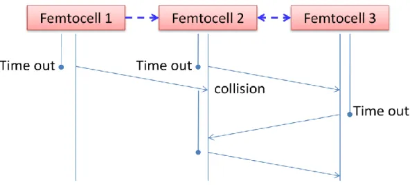
Assumption 4: Femtocells do resource allocation and then broadcast their control information in a random order.
Assumption 1 is the main difference from all of prior arts on resource allocation topic, and the methods proposed for selective fading environment are not suitable for flat fading environment. In OFDMA system, the variation of subchannel condition in frequency domain depends on the subchannel permutation. Because flat fading channel response on MAC layer is a case in the system, and the selective fading effect doesn‟t be included in standard document which defines the femtocell simulation assumptions and parameters, it is adopted in this work. The assumption 2 is based on mobile station requires the same information for the handover process. From the architecture of femtocell network, femtocells are all linked to the backhaul by wire line and applicable to assumption 3. The issue in assumption 4 is more complicate because there is no a coordinator to decide the order of femtocells to do the control decision under distributed control scenario. But this assumption can be realized by applying random timer on each femtocell to decide the control timing. From the time domain it becomes like in an order. If there are two femtocells doing the control decision at the same time, they will notice each other because they need to exchange control information after resource allocation, and the femtocells which collide with others will go into the back off period waiting for next timing. The process is shown in Figure 5.
9
Figure 5 An example of femtocell control order.
2.2 Problem formulation
First, the calculation of SINR values of subchannel qualities for users is formulated here. Assume there are M femtocells and K subchannels. Let Um denotes
the users set served by femtocell m. Pm,k represents the power that the femtocell m transmits on the subchannel k, and Gm,n represents the channel gain from femtocell
m to user n without the index k for subchannels because of flat fading channel model
that Gm,n,k equals Gm,n for all k. The SINR value of the nth user who is served by the mth femtocell on the kth subchannel can be formulated as
M m m m n m k m n n m k m k n G P I N G P SINR ' 1 ' ,' ,' 0 , ,, . N represents the noise power and 0 I represents n
received interference power from macro BSs.
For the total system throughput calculation, we assume femtocells are in close access mode, so the formulation doesn‟t include the parameters for users to
dynamically select the serving femtocells. Let parameter n,k represents the state of subchannel k of user n. n,k 1 represents the n
th
user receives data from its serving
femtocell on the kth subchannel, and n,k 0 vice versa. Because each user is only
10
user, the constraint is expressed as
, 1n k n
for all n and k. The capacity optimization can be formulated as:
Maximize
M m n U K k m m n m k m n n m k m k n m N I P G G P 1 1 ' ,' ,' 0 , , 2 , log (1 ) Subject to Pm,k 0 }, 1 , 0 { ,k n n,k , 1 ,
Um n k n m,k , max 1 , P P K k k m
m , ) 1 ( log 1 ' ,' ,' 0 , , 2 , n K k m m n m k m n m k m k n R G P N G P
n (1)To be more practical with real system, the formulation should change the log2
term into more general function f mapping SINR to bit rate by system defined modulation coding scheme (MCS) threshold. Then user‟s transmission rate is formulated as following:
k k n m k n m n m f SINR R , , ( , , ) ' , (2)Using optimization method to resolve this formulation has some problems. According to the optimization algorithm [31], this optimization formulation is a combinatorial problem and has no efficient method to solve it. Furthermore, even if the formulation could be approximated by other formula to do optimization operation, the constraints in the formulation above might lead to an infeasible solution set. In addition, the formulation is for centralized control algorithm. So most prior arts don‟t incorporate this formulation into their algorithms. In this thesis, we propose a heuristic method for distributed control avoiding directly resolve the optimization formula.
11
Chapter 3. Resource allocation methods
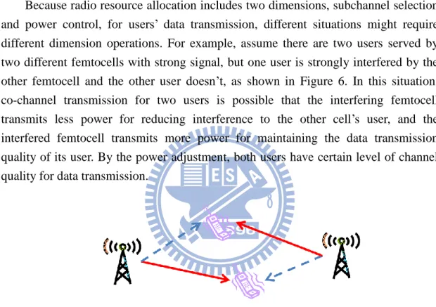
Figure 6 An example of two femtocells environment with one user significantly interfered.
Because radio resource allocation includes two dimensions, subchannel selection and power control, for users‟ data transmission, different situations might require different dimension operations. For example, assume there are two users served by two different femtocells with strong signal, but one user is strongly interfered by the other femtocell and the other user doesn‟t, as shown in Figure 6. In this situation, co-channel transmission for two users is possible that the interfering femtocell transmits less power for reducing interference to the other cell‟s user, and the interfered femtocell transmits more power for maintaining the data transmission quality of its user. By the power adjustment, both users have certain level of channel quality for data transmission.
Figure 7 An example of two femtocells environment with two users significantly interfered.
The situation is different in another example. Assume two users are placed at the locations where each user receives strong interference from the other femtocell, as shown in Figure 7. Power control method can‟t provide a solution for both users having good channel condition to transmit data. If neglecting noise power, the received SIRs, which is a ratio of received serving power to interference power, of two users are still the same if both of femtocells increase or decrease power. Otherwise, one femtocell increasing the power only increases the signal quality of its user but interferes to the other. So in this case, the only orthogonal subchannel selection eliminates the interference from each other.
Multi-user under multi-femtocell scenario is more complicate. The first example of two cells environment discussed before is solved by power control, but it might not
12
be solvable under multi-femtocell scenario because users might have different interference sources coming from other femtocells. Furthermore, because of multi-user in each femtocell, the resource allocation consideration is not only among co-channel or orthogonal channel selection like single user per femtocell case. Under multi-user case, different users under multi-femtocell assigned with the same subchannels require different resource allocation strategy. How to dynamically select subchannels for users is the key issue. Power control is used to enhance system performance after the channel selection.
Following we introduce two simple methods used for performance comparisons in simulation, and detail the proposed method with its process and concept.
3.1 Random channel selection method
This method is for the baseline which doesn‟t have any resource allocation concept. Users under the same femtocell occupy the equal number of subchannels, and users randomly select the subchannels for data transmission. In this method, there is no control mechanism on channel selection and power control, and the method also doesn‟t consider about the QoS issues and users‟ channel condition. It presents the system performances without resource allocation.
3.2 Limited power control method
The key characteristic of this method is that femtocells use all the subchannels for data transmission, and dynamically adjust power to mitigate inter-femtocell interference. The object of this method is to fully utilize the subchannels and save the outage user by reducing transmission power on subchannels.
3.2.1 Subchannel selection
At beginning, every user occupies a group of equal number of subchannels by random selection. After then, the method starts with random chosen femtocell to do resource allocation. Every femtocell separates its users into two groups. One is for those users with channel condition below the minimum data transmission SINR requirement, and the other is for vice versa. The allocation order of users is from users with worst channel condition to users with best channel condition. For the users with low SINRs, they choose the suitable subchannels for transmit. The suitable subchannels are provided by power decrement of strong interfering femtocells. Users with high SINR select the subchannels used by strong interfered users who could be saved by power control under other femtocells. Also there are some users who might have poor channel condition but can‟t find any suitable subchannels or who might have good channel condition but can‟t save any other users. Those users randomly
13
choose subchannels from the left after all the other users have done the selection.
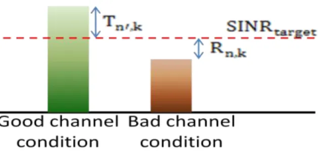
3.2.2 Power adjustment
From the SINR calculation formula,
m m n m k m n m k m k n G P N G P SINR ' ,' ,' 0 , , , , it can besimplified and approximated to SIR,
n m k m n m k m k n G P G P SIR ,' ,' , ,
, , where m’ is the index of maximum interfering femtocell. If a user is in outage, then the femtocell, which is the maximum interfering source to the user, should reduce its power on those subchannels. The user n requests a power reduction of maximum interfering femtocell on subchannel k as:
(3)
The here is a variable that used for power adjustment calculation.
Because the maximum interfering femtocell also has its own user to serve on those subchannels, it has its least tolerant minimum serving power for those users. The power reduction of user n’ on subchannel k it can provide is formulated as:
(4)
The ability of saving users by power control is defined by the difference between
and . means that saving the user n makes the channel
condition of user n’ below minimum data transmission SINR threshold, so the power control is not applicable. Only in this situation the power control can be used to save the user n, and the power of interfering femtocell for user n’ is reduced by in dB. This part is a method for making sure every rescue activity is effective, otherwise the radio resource is wasted. Figure 8 shows the power adjustment using the parameter “target SINR”.
14
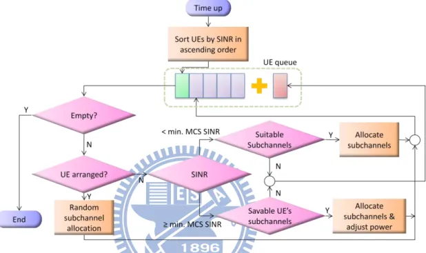
The process of the method executives on femtocells iteratively for merging the solution because at begin femtocells might not find any subchannel reserved for serving its poor user. Here we only consider lowering the subchannel power because if the power can be increased in some cases, it might induce some additional outage users whose original channel conditions are good. This method not only save power but also provide some system performance benefit, at least the reduction of outage rate. The control flow of each femtocell is shown in Figure 9.
Figure 9 Control flow of each femtocell using limited power control method.
3.3 Proposed algorithm
Under the multi-femtocell environment, it seems that power control method for saving users might have some limitation. The orthogonal channel allocation is still the most efficient way to avoid strong interference and save the outage users. How to assign the orthogonal subchannels with other femtocells is an important issue.
According to the modulation coding scheme (MCS) table, listing the minimum SINR requirement of each MCS, it shows that the higher SINR has less difference between threshold values in dB. This indicates that reducing the serving power of users with good channel conditions to mitigate interference for users with bad channel conditions doesn‟t seem like a cost-effective way in system throughput view, unless the femtocell is the source of multiple users‟ maximum interference. This conclusion of observation is like the concept of waterfilling power control which says allocating more power to good channels increases the total capacity.
15
system throughput and also takes care of the QoS requirement of all users. Because orthogonal subchannel allocation requires co-work between femtocells, a trading rule designed in proposed method defines the interaction of femtocells for fairness. Besides, for the preservation of QoS, users‟ conditions about channels and data traffic are considered. The operation of proposed method is separated into three steps. The first step is calculation of subchannel number for each user. Second step assigns candidate subchannels to users. At last the third step classifies the conditions for orthogonal subchannel allocation and does subchannel selection. Because the all process are built on the concept of trading rule, following starts with the description and explanation of trading rule, and then introduces the steps of proposed method.
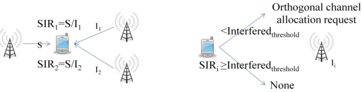
Trading rule is a protocol designed for ruling femtocells exchanging subchannels in proposed method. Orthogonal subchannel partition requires consideration about UEs‟ channel conditions and femtocell cooperation. If a UE asks for using orthogonal subchannels, it not only requires its serving femtocell to allocate UE‟s data transmitted on the particular subchannels, but also requires the interfering femtocells not to use those subchannels. The request helps the femtocells to save poor users but also reduces other femtocells‟ radio resource, so the rule is required for the fairness between femtocells, otherwise every femtocell just sends more request to get better performance of itself.
Trading rule says that a femtocell can require an orthogonal subchannels only by providing an unused subchannel. The setting of exchanging same number of subchannels is for fairness. The requirement exists depending on the comparison of SIR values and “interfered threshold”. UE calculates each SIR values by dividing received serving femtocell power with each received interfering femtocell power. SIR value lower than the interfered threshold means the interfering signal strength is above the acceptable level and the interfered femtocell will transmit orthogonal subchannel allocation request to the interfering femtocell for mitigate interference. The idea of SIR values and the interfered threshold is shown in Figure 10. The following steps of proposed method obey the trading rule.
16
In the first step of algorithm, the amount of radio resource assigned to a user is based on its traffic amount requirement and channel condition. All of users under the same femtocell are assigned a number of candidate channels which is calculated with traffic amount requirement divided by available data transmission rate in subchannels. Because every UE needs to face the bargain, they should prepare double number of candidate subchannels. After the allocation for QoS requirement, the remaining subchannels are assigned with the ratio of UEs‟ data traffic demands for fairness. Each subchannel is assigned the same power budget. Here the reason of allocating user resource budget first is to fulfill QoS requirement and fairness issues at this step.
The users should have different resource allocation arrangements based on their channel condition. After the first step of proposed method, every user has its own power budget and number of subchannels, and these radio resources should be utilized carefully. For the users significantly interfered, the first priority should be increasing its channel quality, which also means orthogonal subchannel allocation by using half number of candidate subchannels for data transmission and the other half number of candidate subchannels for exchange the orthogonal subchannels with other femtocells, because using all the candidate subchannels not only lets the channel quality below the transmission threshold but also brings unnecessary interference into the system, degrading the system performance. On the other hand, users with good channel condition should use all of candidate subchannels under the same limited number of subchannels to increase the system throughput.
With the knowledge of the previous paragraph, the main issue is discussed here: Which users belong to different femtocells should be allocated to the same candidate subchannels? Now considering a two-pair transmission scenario in the same group of subchannels with interference to each other, there are a few kinds of situation discussed as following.
First situation is that both of users have good channel conditions, so it has no need to use separated subchannels because sharing the spectrum by co-channel transmission is more efficient than by orthogonal channel transmission. Under this case, using the orthogonal subchannels for transmission wastes half of subchannels. Although the channel quality of those orthogonal subchannels is better, the spectrum efficiency gain by SINR increment is hardly comparable to the subchannel resource wastage.
The second situation is that one of users has channel condition below the minimum data transmission threshold. If the user is not far below the threshold, it might be saved by power reduction of the other femtocell. But the method, lowering
17
signal power of good users to save poor users, is not cost-efficient that mentioned before, and it is not fair from the femtocell point of view. In addition, the case of users which can be saved by power adjustment seldom exists. The orthogonal channel separation saves most of outage users because of interference elimination, but at meanwhile reduces the throughput of good users. This situation has uncertainty gain of system throughput.
The third case is both of users are in outage. Orthogonal channel allocation for this case is the best way and only way to rescue users from outage. The total system throughput is increased if at least one of them is saved. Power control without orthogonal channel is not effective for this situation. Even the poor channel condition is not caused by strong interfering but weak serving power, using orthogonal channel selection still helps recovering the data transmission.
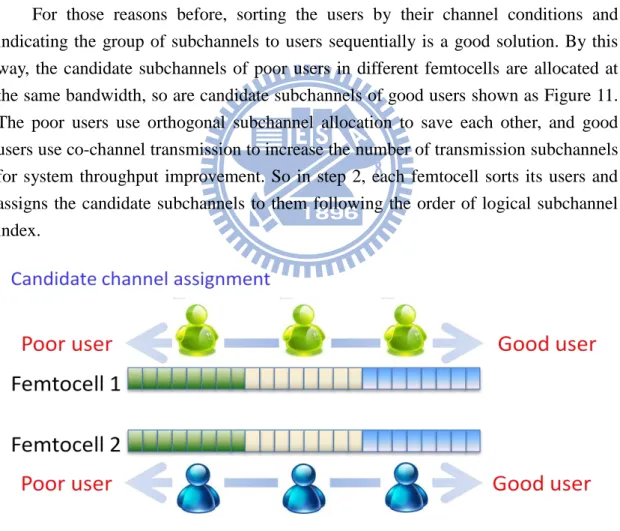
For those reasons before, sorting the users by their channel conditions and indicating the group of subchannels to users sequentially is a good solution. By this way, the candidate subchannels of poor users in different femtocells are allocated at the same bandwidth, so are candidate subchannels of good users shown as Figure 11. The poor users use orthogonal subchannel allocation to save each other, and good users use co-channel transmission to increase the number of transmission subchannels for system throughput improvement. So in step 2, each femtocell sorts its users and assigns the candidate subchannels to them following the order of logical subchannel index.
Figure 11 Assign users subchannels by channel condition
In the last step, the femtocells exchange the control message to do the orthogonal subchannel selection. Femtocells transmit SIR values and index of subchannels by backhaul connection to those nearby femtocells which cause the SIR values below the threshold. After this process, every femtocell knows the channel condition interfered
18
by other femtocells and other cells‟ channel condition interfered by it. After that, the femtocells do resource allocation one by one in a random order mentioned in assumption. For those users with SIR values below the threshold, they are required to do orthogonal subchannel partition. Here includes two kinds of subchannel selection modes. One is concerning strongest interfering or interfered source, and the other one is counting the interfering or interfered times. The first kind of selection mode only considers the channel selection result of strongest interfering femtocell, and the interfered femtocell chooses the subchannels that are not occupied by the strongest interference. The second mode needs to calculate the occupation frequency of interfered and interfering femtocells on each subchannels. Femtocells choose the subchannels with minimum value of occupation frequency for reducing interference. These two modes have small difference but should have similar performance under proper “interfered threshold” condition. This step also includes two power control modes that one is no power adjustment and the other is allocating remaining power on those orthogonal subchannels for improving channel conditions and system throughput. These two power control modes affect the system power consumption. Figure 12 gives an example. After the resource allocation, femtocells need to broadcast its control information to other femtocells to let them know.
Figure 12 Two subchannel selection mode and two power adjustment mode
This method requires 4 parts of information exchange. At first, femtocells send control signal like preamble or pilot signal to let users measure the channel condition and SIR values. Secondly, UEs send the SIR values with femtocell indexes which below the SIR threshold to its serving femtocell. Third, femtocells exchange the SIR values and indexes of subchannels by backhaul to aware the nearby cells. At last, each femtocell transmits its control decision to warn other femtocells which haven‟t do resource allocation yet. The information exchanges in proposed algorithm don‟t cost too much radio resource because most information goes by backhaul, and the amount is small. Whole process is showed in Figure 13.
19
Figure 13 Procedure of information exchange.
The control flow of each femtocell based on proposed method is like Figure 14.
20
Chapter 4. Simulation setup
The simulation environment is based on LTE standard document [24].
Figure 15 19 Macro cells as two tier interference model and femtocell model location[23]
19 macro cells model is a common scenario for analyzing the macro BS effect. Except the central cell, 18 macro cells surrounding is act as two-tier interference. Dense femtocell deployment model is adopted in this simulation. The femtocell environment is placed in central macro cell coverage as Figure 15 shows, and the distance between block and center BS is 600 meters. Figure 16 is the dense femtocell deployment model which models two apartment buildings across street and each has 20 rooms side by side. Every room is placed a femtocell which is uniformly random location. 10 m 10 m 10 m 10 m 10 m
Figure 16 The standard dense femtocell deployment model [24]
21
Table I Macrocell parameter
Parameter
Assumption
Cellular Layout Hexagonal grid, 3 sectors per site, reuse 1. Inter-site distance 500 m or 1732 m
Number sites 19 (=57 cells) or 7 (=21 cells) with optional wrap-around.
Carrier Frequency 2000 MHz Distance-dependent path loss See section 5.2 Shadowing standard deviation 8 dB (see section 5.3) Auto-correlation distance of Shadowing
(optional)
50 m (see section 5.3) Shadowing
correlation
Between cells 0.5 (fixed, see section 5.3) Between sectors 1.0 (see section 5.3) Penetration Loss (assumes UEs are indoors) 10dB or 20dB (see section 5.2)
Antenna pattern (horizontal)
(For 3-sector cell sites with fixed antenna patterns)
See section 5.1 BS antenna gain after cable loss
14 dBi BS noise figure
5 dB Number of BS antennas
2 Rx, 2 Tx UE Antenna gain 0 dBi UE Noise Figure 9 dB Number of UE antennas
2 Rx, 1 Tx Total BS TX power (Ptotal) 46 dBm
UE power class 23 dBm (200 mW)
In order to keep the simulations simple it is not necessary to model Maximum Power Reduction (MPR)
versus modulation scheme.
Inter-cell Interference Modelling Explicit modelling (all cells occupied by UEs) Antenna Bore-sight points toward flat side of cell
(for 3-sector sites with fixed antenna patterns)
Traffic model Full buffer initially with 10 UEs per sector. Other traffic models (e.g. bursty traffic models) should be looked at later, and that the associated model(s)
to use need to be selected and documented. UE distribution UEs dropped with uniform density within the
indoors/outdoors macro coverage area, subject to a minimum separation to macro and HeNBs. The probability of a macro UE being indoors should be a parameter rather than being fixed at one, depending
on the scenario being investigated. Minimum distance between UE and cell >= 35 m
UE speeds of interest 3 km/h
Fading model Ray based or correlation matrix based (see section 4.3)
DL Receiver Type MRC (single stream) or MMSE (multiple streams). Multiple streams MIMO is optional.
Other MIMO modes should be looked at after the initial studies.
22
Femtocell parameter is defined in Table II.
Table II Femtocell parameter
Parameter Assumption
HeNB Frequency Channel Either same frequency and same bandwidth as macro layer, or adjacent channel and same bandwidth as macro
layer Min separation UE to HeNB 20 cm [2]
Number Tx antennas HeNB 1 (baseline) 2x2 MIMO is optional
Other MIMO modes should be looked at after the initial studies
Number Rx antennas HeNB 2
HeNB antenna gain 0 dBi or 3 dBi or 5 dBi Exterior wall penetration loss 10 or 20 dB (See section 5.2)
Interior path loss model See section 5.2 Interior to Exterior path loss model See section 5.2 Exterior path loss model HeNB to UE See section 5.2 Log-normal shadowing standard deviation 4 dB
10 dB in the simplified model in the Urban case when no internal walls are modelled (See section 5.2) Shadowing auto-correlation distance for HeNB
(optional)
3 m Noise figure HeNB 8 dB Min/Max Tx power HeNB 0/20 dBm
Carrier bandwidth 10 MHz Number RBs for PUCCH 4 Number of symbols for PDCCH 3
Channel model includes 3 major parts: antenna patterns, pathloss, and shadowing. For the type that macro cell has 3 sectors, the directional antenna with 120o angle coverage serves coverage of a sector. The azimuth antenna pattern is calculated as following:
m dBA
A
min
12
,
2 3
(5)For femtocell and UE, they both are assumed to use omnidirectional antenna, so antenna pattern is 0dB for all angle.
The pathloss formulation is defined as Table III. The parameter Liw and Low
describe the penetration loss of indoor walls and outdoor walls. In the simulation we assume the Liw as 5dB and Low as 10dB because the indoor walls are usually thinner
23
Table III Pathloss formulation
Cases Path Loss (dB) UE to macro BS (1) UE is outside PL (dB) =15.3 + 37.6log10R, R in m (2) UE is inside an apt PL (dB) =15.3 + 37.6log10R + Low, R in m UE to HeNB (3) Dual-stripe model: UE is
inside the same apt stripe as HeNB
PL (dB) = 38.46 + 20 log10R + 0.7d2D,indoor+ 18.3 n ((n+2)/(n+1)-0.46) +
q*Liw
R and d2D,indoor are in m
n is the number of penetrated floors
q is the number of walls separating apartments between UE and HeNB In case of a single-floor apt, the last term is not needed
(4) Dual-stripe
model: UE is
outside the apt stripe
PL (dB) = max(15.3 + 37.6log10R, 38.46 + 20log10R) + 0.7d2D,indoor
+ 18.3 n ((n+2)/(n+1)-0.46) + q*Liw + Low
R and d2D,indoor are in m
q is the number of walls separating apartments between UE and HeNB (5) Dual-stripe
model: UE is
inside a different apt stripe
PL(dB) = max(15.3 + 37.6log10R, 38.46 + 20log10R) + 0.7d2D,indoor
+ 18.3 n ((n+2)/(n+1)-0.46) +q*Liw + Low,1 + Low,2
R and d2D,indoor are in m
q is the number of walls separating apartments between UE and HeNB (6) Dual-stripe model or 5x5 Grid Model: UE is within or outside the apartment block PL(dB) = 127+30log10(R/1000) R in m
This is an alternative simplified model based on the LTE-A evaluation methodology which avoids modelling any walls.
Shadowing model uses log-normal distribution to generate random values for all links. The standard deviation is 4dB between serving BS and UE, and 8dB for all others. Correlation of shadowing is also considered, but it only exists for links from one UE to multi BSs, not for links from multi UEs to one BS.
24
Chapter 5. Simulation result
In the simulation result, the proposed method, which includes different subchannel selection modes and power adjustment modes, is compared with random subchannel selection method and limited power control method.
Following has three parts. The first part we adjust the values of “target SINR”, which is a parameter used to calculate the target power ratio adjustment in limited power control method, and “interfered threshold”, which is a distinguish standard for interference, in methods to see the effects on performance including system throughput, user outage rate, and power consumption. In the second part, the parameters are fixed to see the fairness issues of user throughput and femtocell throughput. In the third part, the number of users under each femtocell is adjusted to analyze the resource allocation gain of multi-user case. Here the system throughput is calculated by mapping SINRs to spectral efficiency in Table IV [25] and using the definition of transmission data unit in LTE to calculate the number of bits in resource source blocks.
Table IV MCS mapping table [25]
Modulation Code rate SINR (dB) Spectrum efficiency
QPSK ½ 3.50 1.00 b/symbol QPSK ¾ 6.50 1.50 b/symbol 16QAM ½ 9.00 2.00 b/symbol 16QAM ¾ 12.50 3.00 b/symbol 64QAM ½ 14.50 3.00 b/symbol 64QAM ⅔ 16.50 4.00 b/symbol 64QAM ¾ 18.50 4.50 b/symbol
5.1 Target SINR & interfered threshold effect
25
subchannels. Users have the same minimum transmission rate requirement, 128kbps, which is a general requirement of data traffic. There are 3 kinds of system performance evaluated to show the difference between methods.
5.1.1 System throughput
Figure 17 System throughput variation with target SINR or interfered threshold values.
The system throughput ratio indicates the system throughput improvement compared to the limited power control methods. The formulation is as following,
(6)
From the result in Figure 17, for the limited power control method, when the “target SINR” value is lower than the minimum data transmission threshold, it makes the interfering users reduce their serving power until below the transmission threshold that whichever interfering or interfered users are unable to receive the data, so the system throughput reduces about 5%. For the “target SINR” value is higher than the minimum data transmission threshold, the system throughput seems at most only 1% improved if the proper “target SINR” value is chosen. This result is because the throughput increment from saving a poor channel condition user is diminished by
0.8 0.85 0.9 0.95 1 1.05 1.1 1.15 1.2 1.25 -20 -15 -10 -5 0 5 10 15 20 25 30 R atio
Target SINR or interfered threshold(dB)
System throughput Random selection method Limited power control method Proposed method multi interference Proposed method multi interference power adjusted Proposed method max interference Proposed method max interference power adjusted
26
decreasing throughput of good channel condition users. If the value of “target SINR” is set too high, there are no any good channel condition users can match the power control requirement, and no power adjustment happens. The figure also shows that proposed method, no matter what kind of modes, brings about 19% improvement of system throughput if proper value of “interfered threshold” is selected. The system throughput increases with the parameter value below 8dB, but when the value becomes higher than 8dB, the system throughput starts to decrease. The reason is that higher “interfered threshold” value makes more orthogonal channels helping poor users, but when value is above 8dB, more users which don‟t interfere with each other are allocated in orthogonal channels decreasing the throughput of good users. For the channel selection modes, the mode counting interfering number get a little bit better system throughput when “interfered threshold” value is about 8dB because of utilizing the less occupied subchannels, but it decreases fast when “interfered threshold” value goes bigger than 8dB for the reason that poor users are mislead by the count of interfering times but don‟t notice which are the real interference. In general the strongest interference decides the channel conditions of users here. The maximum interference mode has better performance than random selection method even when the “interfered threshold” value is too high. Power adjusted mode provides a little improvement on system throughput because the channel quality is improved.
5.1.2 Outage probability
Figure 18 Variation of user outage rate with target SINR or interfered threshold values. 0 0.05 0.1 0.15 0.2 0.25 0.3 0.35 0.4 -20 -15 -10 -5 0 5 10 15 20 25 30 R ate
Target SINR or interfered threshold(dB)
User outage rate
Random selection method Limited power control method Proposed method multi interference Proposed method multi interference power adjusted Proposed method max interference Proposed method max interference power adjusted
27
The outage probability is calculated with the number of users who can‟t reach their requirement of transmission rate divided by total number of users. Following is its formulation.
(7) Figure 18 shows that original control method has about 32% outage rate, and the best of limited power control method is about 24% outage rate, only 1/4 of the original outage user saved. But both are above the 10% outage rate which is the requirement of standard systems. The “target SINR” value could lead to a misunderstanding of capability of saving users when value is low and underestimate the number of users could be rescued when value is high, so the outage rate increases when the “target SINR” value is lower than 4dB, and the outage rate is back to the original when the “target SINR” value is high. Proposed method makes the user outage rate become only about 4% at “interfered threshold” value 6dB, and this result proves the ability of orthogonal subchannel assignment of mitigating interference. For the channel selection mode by the interference count, the graph shows that outage rate not only slightly higher when low “interfered threshold” value which is intuitive because of underestimate the impact of interference, but also when “interfered threshold” value is high for the reason that the femtocells include more interfering sources into consideration and neglect the weighting of the strongest interference effect. The maximum interference mode doesn‟t increase the user outage rate with “interfered threshold” value. The power adjustment helps little on user outage rate because the orthogonal subchannel partition has done the interference mitigation.
28
Figure 19 Power consumption ratio with target SINR or interfered threshold values.
Because the limited power control method and proposed method without power adjustment don‟t fully utilize the power budget of femtocell, this part wants to see the power saving difference between methods. The power consumption of random channel selection method is used as comparison objective. The formulation is:
(8)
From the Figure 19, although the limited power control method uses the power reduction to mitigate interference, it saves only 8% power when the “target SINR” value is 3dB where the method decreases the system throughput and doesn‟t help reducing the user outage rate. For the proposed method without power adjustment, the higher “interfered threshold” value brings more power saving effect. But considering the other two effects before, the value of “interfered threshold” about 8dB should be chosen. At “interfered threshold” value 8dB, both of the channel selection modes use 68% of original system power consumption. This part shows that proposed method without power adjustment has a little less system throughput improvement compared to the proposed method with power adjustment but provides about 32% power saving.
5.2 Fairness Issue 0.5 0.6 0.7 0.8 0.9 1 1.1 -20 -15 -10 -5 0 5 10 15 20 25 30 R atio
Target SINR or interfered threshold(dB)
Power consumption Random selection method Limited power control method Proposed method multi interference Proposed method multi interference power adjusted Proposed method max interference Proposed method max interference power adjusted
29
In this part, the “target SINR” or “interfered threshold” values are fixed at 8dB. There are 2 kinds of system performance about fairness evaluated to show the difference between methods.
5.2.1 user throughput distribution
Figure 20 CDF of user throughput.
The user throughput distribution graph is shown in Figure 20. The curve of limited power control method is more fairness because it lowers the throughput of good users to save poor users, but compensate the total system throughput. Proposed method shifts many users from zero values of throughput to some acceptable points with a little decrease of good users, so the curves are more oblique. The curves are closed with different channel selection modes because both have similar control result at the assigned “interfered threshold” value. The power adjustment mode gives the poor users better channel condition but lower the good users‟, but the difference is small.
5.2.2 femtocell throughput distribution
0 0.2 0.4 0.6 0.8 1 1.2 0 2 4 6 8 10 12 14 16 18 Pr o b ab ili ty UE throughput (x84kbps) User throughput CDF Random selection method Limited power control method Proposed method multi interference Proposed method multi interference power adjusted Proposed method max interference Proposed method max interference power adjusted
30
Figure 21 CDF of femtocell throughput.
Except to the user throughput, here we also consider about the individual femtocell throughput, showed in Figure 21. Random channel selection method and limited power control method have the similar distribution and the throughput of the femtocells is scattered which means less fair. In contrast, the proposed method, including all kind of modes, has more oblique curves which mean the throughput of femtocells is balanced. And this benefit comes from reducing the number of the low throughput femtocells but not reducing the number of the large throughput femtocells.
5.3 Number of user effect
In this part, the user number of each femtocell is adjusted from 1 to 8, and subchannel number of femtocells is 4 times of user number. The “target SINR” or “interfered threshold” values are fixed at 8dB. There are 3 kinds of system performance evaluated to see the multi-user effect on methods.
5.3.1 System throughput 0 0.2 0.4 0.6 0.8 1 1.2 0 5 10 15 20 25 30 35 40 45 50 55 Pr o b ab ili ty Femtocell throughput(x84kbps) Femtocell throughput CDF Random selection method Limited power control method Proposed method multi interference Proposed method multi interference power adjusted Proposed method max interference Proposed method max interference power adjusted
31
Figure 22 Variation of system throughput improvement with number of UE per femtocell.
Figure 22 shows that comparing to the random channel selection method, the limited power control method holds the same system throughput and doesn‟t change with number of the users, but proposed method can get higher system throughput improvement when the number of the users increases. The outcome is related to the sorting process that assigns the poor users at the same subchannels and do orthogonal channel partition. When the number of user is small, the sorting effect is not quite significant because every femtocell might have multi good users or multi poor users at the same time that some poor users might be placed on the subchannels that good users use or vice versa. When the number of the users increases, the distribution of users‟ channel condition is more balance, so the probability that poor users and good users use the same subchannels is decreased.
5.3.2 User outage rate
0.8 0.85 0.9 0.95 1 1.05 1.1 1.15 1.2 1.25 1.3 1 2 3 4 5 6 7 8 R atio
Number of UE per femtocell
System throughput Random selection method Limited power control method Proposed method multi interference Proposed method multi interference power adjusted Proposed method max interference Proposed method max interference power adjusted
32
Figure 23 Variation of user outage rate with number of UE per femtocell.
The user outage rate of random selection method and limited power control method is no much variation under different number of the users, shown in Figure 23. But for proposed method, the user outage rate slightly increases with the number of the users. The reason of this situation is that the more poor users are contending the same subchannels increasing the probability of collision, so the user outage rate raises. But from the result the increment of outage rate is only about 1%.
5.3.3 Power consumption 0 0.05 0.1 0.15 0.2 0.25 0.3 0.35 1 2 3 4 5 6 7 8 R ate
Number of UE per femtocell
User outage rate
Random selection method Limited power control method Proposed method multi interference Proposed method multi interference power adjusted Proposed method max interference Proposed method max interference power adjusted
33
Figure 24 Variation of power consumption ratio with number of UE per femtocell.
Still only the proposed algorithm without power adjustment changes with number of the users in Figure 24. The reason is the same as two performances before that the amount of good users allocated at subchannels for poor users decreases, so the number of the orthogonal subchannels is averaged to half which also means the power consumption should approach to 75%. The graph, Figure 24, shows the trend.
0.5 0.6 0.7 0.8 0.9 1 1.1 1 2 3 4 5 6 7 8 R atio
Number of UE per femtocell
Power consumption Random selection method Limited power control method Proposed method multi interference Proposed method multi interference power adjusted Proposed method max interference Proposed method max interference power adjusted
34
Chapter 6. Conclusion
This thesis focuses on the downlink resource allocation in dense femtocell deployment scenario. A method using orthogonal channel allocation concept is proposed for enhancing the multi system performances. Multi performance indexes are simulated under LTE standard definition environment and discussed. The simulation results show that the proposed method reaches the highest increment of system throughput, better balanced throughput of users and femtocells, lowest user outage rate and power consumption even it doesn‟t fully utilize the radio resource blocks. The proposed method with different power adjustment modes shows that power adjustment for interference mitigation is not effective, and the proper reservation of channel usage doesn‟t waste the radio resources but provides benefits to the whole system. For the future work, the resource allocation method should combine in the scheduling mechanism. MIMO, the essential technique in new wireless systems, and selective fading effect should be considered in the system design.
![Figure 1 Introduction of femtocell [2]](https://thumb-ap.123doks.com/thumbv2/9libinfo/8553040.188244/9.892.185.709.849.1068/figure-introduction-of-femtocell.webp)
![Figure 2 Interference scenarios [4]](https://thumb-ap.123doks.com/thumbv2/9libinfo/8553040.188244/10.892.140.765.863.1064/figure-interference-scenarios.webp)
![Figure 3 Backhaul structure of femtocell [5]](https://thumb-ap.123doks.com/thumbv2/9libinfo/8553040.188244/11.892.144.742.522.954/figure-backhaul-structure-of-femtocell.webp)
![Figure 4 Process of self-organization [6]](https://thumb-ap.123doks.com/thumbv2/9libinfo/8553040.188244/12.892.225.680.529.1057/figure-process-of-self-organization.webp)