AUTOMATIC WHITE BALANCE FOR DIGITAL STILL CAMERA Yung-Cheng Liu, Wen-Hsin Chan and Ye-Quang Chen
Industrial Technology Research Institute ITRI/OES, 195-8, Sec. 4, Chung-Hsing Rd.
Chutung 31 0, Taiwan, ROC
Abstract
A new algorithm of automatic white
balance for electronic images has been developed. This algorithm uses h z z y logic rules for determinationi of the color parameters in order to minimize the color temperature difference of various light sources. This algorithm has been implemented in a newly designed electronic still camera, and resulted in highly improved image quality.
I. Introduction
An object may appear different in color when it is illuminated with different light sources. This is due to the color temperature difference of the light sources, which induces the shift of the reflection spectrum of the object from the "true" color. When a white object is illuminated with low color temperature light source, the reflection becomes reddish. On the other hand, the high temperature light source causes bluish in color t o the same white object. The human vision may not be able to distinguish the color difference due t o the "color constancy"1 of human eyes. However, for an image recording media such as photographic films or video tapes, the reflected light of an object from a given light source will be recorded, and results in a color difference, if the light source is not standard.
To compensate this color difference caused by various light sources, a white balance
mechanism is employed in most electronic cameras. Usually, a color video signal from a sensor can be decomposed into red, green, and blue components, or other components in color space. The signal of each color can have its own amplifier. To adjust these amplifiers with different gains, the composite color can be corrected to near " true" color.
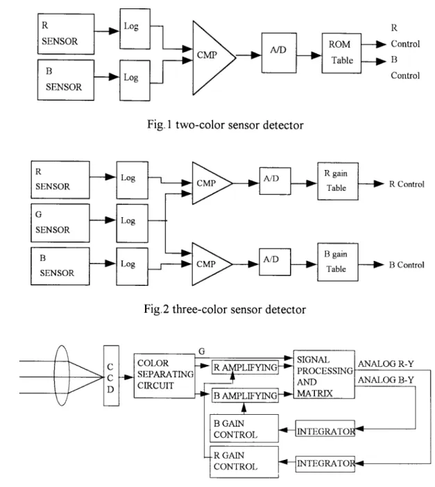
For white balance adjustment, the traditional mechanism in an electronic camera uses color sensors to measure the color intensity of the environmental illumination. The hnctional block diagrams for two and three sensor systems are shown in the Fig.1 and Fig.2 respectively. The two-sensor system uses sensors with red and blue optical filters for detection and measurement. The output signal of each sensor passes a logarithm pre-amplifier. The ratio of these two color signals is obtained by a divider ( C M P ) , then it is digitized after an A/D
converter. Using a table stored in a ROM (read only memory), this digitized ratio is converted to corresponding gain factors for the image color adjustment.
The three-sensor system uses red, green, and blue sensors for color measurement. The ratio of red to green is employed for red color gain control, and the ratio of blue to green is for blue color gain control. As a result, a normal color of digital image can be obtained by this mechanism.
Liu, Chan and Chen: Automatic White Balance for Digital Still Camera 46 1
f
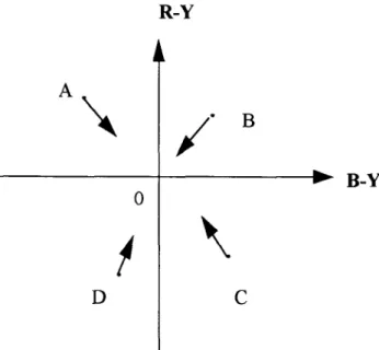
In addition to the color sensor systems, another method is to use the image sensor (usually CCD, charge-coupled devices) as a color sensor for color measurement. In an analog electronic camera, the output signal of a CCD can be decomposed into the luminance Y, and the chrominance R-Y and B-Y. The integrated values of both R-Y and B-Y over one image frame can be calculated. These values are used for the controls of red and blue color amplifiers. The functional block diagram of this system is shown in Fig. 3.
\
R-YCODE H D I C U V
Light Horizon Daylight ITC A Cool Ultraviolet
B-Y
0
Fig.4 the (R-Y)-(B-Y) 2-dimension coordinate The integrated values of both R-Y and B- Y can be plotted on a R-Y, B-Y coordinate system. Fig. 4 shows an example of four different types of A, B, C, and D points. The
deviations of these points from the origin 0, which is at the white balance, need to be corrected in the arrow direction in order to approximate the 0 point. This method is under the assumption that the integrated values of a color picture are at white color. The bias toward blue or red color is introduced by the color temperature of a light source. However, when a large object or background with a uniform color, the color compensation may cause the loss of integrity of the color.
The following sections will describe an automatic white balance algorithm used in a digital still camera. This method will reduce the effect of a large object with uniform color in an image field of view. The fuzzy theory is employed for the color gain determination, therefore experiments are implemented to get statistic results. These experiments are described
in Section 2. The results and concluded fuzzy rules are discussed, and the algorithm based on those fuzzy rules in a digital electronic camera is described. Section 3 gives the testing results of the algorithm. The conclusion of this study is giver, in Section 4.
2. Experiment
A CCD based camera was used for this
experiment. The digital signals of a color image can be decomposed into three components: Y, Cr, and Cb; where Y is the intensity, and Cr, Cb are the color components, according to CCIR-
601 standard. The pixel data Y, Cr, Cb are accumulated over an image frame. Objects with various colors were illuminated with difference light sources. The result data are plotted on Cr- Cb coordinates.
The light source used in this experiment and their codes are listed in the table 1.
Table 1. light source names and their codes Any uniform color can be represented with a point on the Cb-Cr coordinate system. A monochromatic object illuminated with a standard light source will be on a nominal position on the Cb-Cr coordinate. However, with different light sources or light intensity, the position will deviate toward Cb (indicate bluish)
R SENSOR
+
G SENSOR---w
R gain --b Table ---b N D Log Log -. Control B Table f'nntrnl N D-
B SENSORFig. 1 two-color sensor detector
B gain
Table
-
-IR
WLIFYINGk 'IGNAL PROCESSING COLOR+ SEPARATING
Fig.:! three-color sensor detector
ANALOGR-Y ANALOG B-Y Control Control B GAIN CONTROL
I :
I IFig.3 automatic white balance in analog electronic camera The above white balance circuits have
been used for electronic cameras for years, but there are the following drawbacks:
1) The spectral responsibility of a color sensor is different from image sensor, hence the color compensation is limited.
2) Usually a color sensor has limited dynamic range, therefore it is not effective in bright or dim environment,
3 ) The analog signal processing prior to the A/D converter may be effected by the temperature variation. The calibration may be required.
4) An extra room is required to house the sensors in camera assembly.
5 ) The view angle of color sensor should be close to the camera lens. This will introduce extra design effort.
Liu, Chan and Chen: Automatic White Balance for Digital Still Camera 463 Axis of low 4 color temperature \ A \ Green L A Cr B, Pink L A white
-
color temperaturebA
AeruginousA : the deflected direction of high color temperature B : the deflected direction of low color temperature
Fig.5 the experimental data of colors under different light sources. or Cr (reddish) coordinate. Some of the
experimental results are summarized in the Figure 5.
The experimental results depict that:
1) A dark color has less deviation from nominal position under different light sources, as opposed to the bright color, where the deviation is significant on the Cb and Cr components;
2) When a white object is illuminated
with different light sources, the slope of deflection, i.e. the ratio of Cr to Cb, r=Cr/Cb, is about between -1.5 and -0.5;
3) At high luminance, the color components are easy to be saturated; while at low luminance, the color components become colorless.
The automatic white balance algorithm has been developed. A frame of image captured with a CCD camera can be divided into 8
segments for weightings. Fig.6 shows two types of segmentation. The averages of Cr and Cb components of all pixels within each segment are calculated, and then weighted under h z z y
control means. Based on experimental results,
the h z z y rules were described below:
U U DS P modul :
,
I
I
image buffer control interface Fig.6b division of frame (11)Monitor
DSCBODY CAMERA HEAD
n
POmpress& memory bufferI
7
Fig.7 a simulation block diagram of automatic white balance
1 ) At high luminance, the color components are easy to be saturated, while at low luminance, the color components become colorless. Hence, the Cb and Cr will be weighted with small value under the conditions of high end and low end luminance.
2 ) The averages of Cb and Cr for each segment are weighted less for dark colors than bright colors.
3 ) When a large object or a background occupies more than one segment, its color will
dominate that segment. The r value will be similar among adjacent segments. In this case, the given weighting for that segment is small in order to avoid over compensation on the color of the picture. Otherwise, if r is very different from the adjacent segments, and is about between -1.5 to -0.5, the given weighting is large.
Fig.7 is the block diagram of a simulation for the development and testing of an automatic white balance algorithm. This simulation system consists of a camera head, a digital still camera (DSC), a monitor, an image buffer, and a 486 personal computer. The camera head and the DSC were designed in our laboratory. The image is captured by a CCD area array. The output signals from CCD are converted into 10
bits' digital data. Those raw data are then prccessed with a DSP/IC (digital signal processor integrated circuits) to implement color conversion, interpolation, and coding. The result digital output consists of Y, Cb, Cr components for each pixel. The full image frame is then stored in an image buffer. The testing algorithm is executed and evaluated in the 486 PC.
As discussed before, the image is divided into 8 segments. The averages of Cb and Cr for each segment are calculated. Then the weighting factors for each segment are determined, based on the hzzy control means, to calculate the evaluatkg Cb' and Cr' of the whole image frame. The Cb' and Cr' indicate the deviation of the
imagg color from the white balance point. These values are employed to obtain the gains for Cb and Cr of each pixel. The averages of adjusted Cb and Cr are calculated. If the result is not close to the white balance point, the iteration
wi!! be performed, Fig.8 is a flow chart of
the white balance algorithm using fuzzy control means.
3. Result
During the experiment and the development of the algorithm, the Cb and Cr
Liu, Chan and Chen: Automatic White Balance for Digital Still Camera 465
values showed a strong correlation with the color temperature. As expected, the low color
temperature gives reddish image, while the high color temperature gives bluish image.
f%
Initialize parametersranges of 8 windows
Read Y
-
Cb and Crfrom memory buffer of DSC
(
'
1
Accumulating Y-
CbI
R * Bgainand Cr of all piexls in each window
I
Calculate weighting Cb & Cr values byI
fuzzy control balanceFig.8 flow chart of white balance by
fuzzy
control means.
Fig.9a an uncorrected image
Fig.9b a corrected image
Fig.9a is a picture exposed under low color temperature. The color is reddish. Using the automatic white balance algorithm, the color is corrected as shown in Fig.9b. The picture was divided into 8 segments, The 8 sets of Cb, Cr averages are plotted on a Cb-Cr coordinate system (Fig loa, symbol " . ' I ) . M e r weighting
for each segment, based on the
fuzzy
control mean, the Cb' and Cr' were obtained and is plotted with a symbol of "x". The deviation is used for Cb and Cr gain adjustments for all pixels. The averages of adjusted Cb, Cr for each segment were calculated again, and the induced Cb' and Cr' were obtained. The result (Fig lob) shows that the Cb and Cr for each segment shift toward the origin, and the final Cb' and Cr' arevery close to white balance point. The improvement on the picture in color is significant (Fig. 9b).
4. Conclusion
This automatic while balance feature has been included in a newly designed digital camera prototype. The algorithm was implemented with FPGA circuit in order to have real time processing. The performance on white balance is significantly improved. This method uses the picture segments with different weightings, which minimize the color effect of large objects and background. The h z z y control rules were obtained with experimental data. Therefore, using these rules for gain determination gives the optimal performance on white balance.
Biography
Yung-Cheng Liu was born in Chang-Hwa, Taiwan R.O.C., in 1965. He received his B.S. degree in electronics at Chung-Yuan Christian University, in 1988, and then received his M.S. degree in Institute of Optical Science at National Central University, in 1990. He is a member of the Chinese Image Processing and Pattern Recognition Society, and is with Opto- Electronics & System Lab. of Industrial Technology Research Institute since 1990. His research interests include the development of Opto-electronic system, image processing and digital video camera system.
Wen-Hsin Chan received his Ph. D. degree in Electrical and Computer Engineering from State University of New York at Buffalo in 1984. From 1984 to 1985, he was a senior engineer with the Remote Sensing Group at Lockheed Aerospace Company. From 1985 to 1992, He was a staff engineer with Guidance System Division at Allied-Signal Bendix Inc. Since 1992, he has been at the Industrial Technology Research Institute in Taiwan, where he has served as a deputy director in the
Cr
Fig. 10a
Cr
\L
Fig. 1 Ob
Planning and Promotion Division, and currently as a manager in the image processing department.
Reference
1 ) Peter Gouras, "The Perception of Colour", New York, USA, 199 1.