Combined Private and Public Watermarking in Wavelet Transform Domain
10
0
0
全文
(2) 1.. Introduction. rithms are more robust than the public ones [2][7]. Wavelet-based. The rapid development of the Internet and. methods. become. more. digital technology makes it easy and efficient to. prevalent in transform-domain watermarking. distribute multimedia data than before. How-. community due to their excellent spatial local-. ever, because digital data, including audio,. ization and frequency spread characteristics.. video, images, and documents, could be dupli-. Moreover, increasing research results in the. cated and modified without difficulty, there is. literature show that the wavelet-based tech-. an urgent need for copyright protection in the. niques provide the superior robustness to vari-. e-commerce era. Digital watermarking is a. ous signal processing attacks and loosy com-. technology of embedding a hidden signal into. pression. The proposed method focuses on. digital contents to identify the legitimate owner,. digital watermarking for gray-level images us-. track unauthorized use, or detect intentional. ing wavelet transform, which can be conven-. tampering of the original data. Digital water-. iently integrated in forthcoming compression. marking plays an important role in these. standards, such as JPEG 2000 and MPEG 4.. applications and draws universal attention both. With the standardization process of JPEG 2000. in academia and business over the last decade.. and the shift from discrete cosine transform. The most important key requirements of wa-. (DCT) to DWT method, watermarking schemes. termarking schemes are imperceptibility and. operating in the wavelet transform domain have. robustness. That is, the embedded watermark. become even more enthralling and pressing. must be perceptually invisible and difficult to. [3][4]. The proposed technique embeds two wa-. destroy without severe degradation in media. termarks into different middle-frequency sub-. fidelity [1]. According to the necessity of original me-. bands to compromise between the transparency. dia when extracting a watermark, watermarking. and the robustness requirements mentioned. systems can be classified into private and pub-. above, based upon the following two main rea-. lic ones (the latter is also referred to as blind or. sons [5].. oblivious watermarking). Private algorithms. Human visual system (HVS) is more sensi-. need the original media and possibly distorted. tive to lower frequency noise.. one during detection, which limits their usage. Higher frequency coefficients are susceptible. since original media are difficult to obtain. to be suppressed by loosy compression.. sometimes. On the other hand, public algo-. Unlike traditional watermarking algorithms,. rithms, requiring neither the original media nor. which embedded either a random number of a. the embedded watermark, have much wider. sequence of bits or a visually recognizable pat-. applications such as broadcast monitoring,. tern as a watermark into the original image at a. copy control, and transactional watermark (also. time, the proposed algorithm embeds two bi-. known as fingerprinting) but remain the chal-. nary watermarks all with values 0 or 1 for the. lenging problems. In general, the private algo-. copyright protection enhancement [6]. Specifi-. 2.
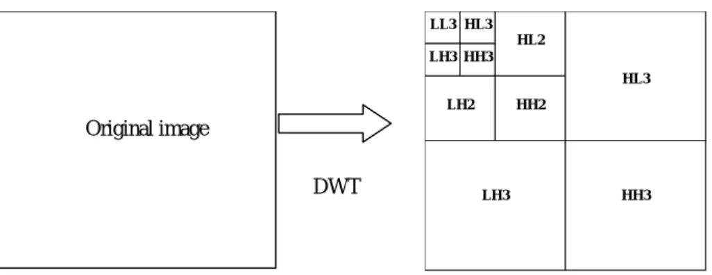
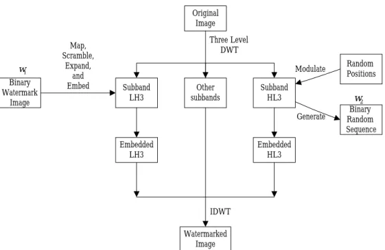
(3) cally, one is a visually recognizable binary im-. binary random sequence with length P. The. age; the other is a binary serial number (called. algorithm of the proposed combined water-. w1 and w2 in the rest of this paper, respec-. marking is presented below.. tively). The w1. 2.1. can be designed as the. The block diagram for embedding proce-. owner’s seal, signature, or an organization’s logo. The w2. Embedding Procedure. stands for buyer’s unique. dure is shown in Fig. 2. The original image X is. information that could be identified as the legal. decomposed into three levels with ten subbands. recipient of the copy, and used to trace the. of a wavelet structure Y. The embedding steps. source of illegally redistributed content. These. of w1 and w2 are performed as follows, re-. are potentially useful both as a deterrent to in-. spectively.. fringement of copyright and a scientific aid to. ′ 3 ( i, j ) , and c′HL 3 ( i, j ) denote the original cLH. investigation.. and watermarked coefficients of subbands LH3. The remaining paper is organized as fol-. Let. cLH 3 ( i, j ) ,. cHL 3 ( i, j ) ,. and HL3, respectively.. lows. In Section 2, the details of the proposed. 2.1.1. Embedding steps of w1. watermarking algorithm are given. The ex-. Step 1: Map the watermark w1 content values. perimental results of the proposed algorithm. 0 to –1, scramble its spatial relationship,. are shown in Section 3. Finally, the conclusions. and expand the size of w1 to the same. are drawn in Section 4.. of LH3 subband. More precisely, each pixel in w1 is expanded with size. 2. THE PROPOSED METHOD. M M × . 8N 8N. By using wavelet transform, a whole image. Step 2: Perform the watermark w1 casting by. is decomposed into four subbands, i.e., low. using the spread spectrum technique de-. frequency subband (LL), high-low frequency. fined as:. subband (HL), low-high frequency subband ′ 3 (i, j ) = cLH 3 (i, j ) × (1 + α × ω1 (i, j ) ) , cLH. (LH), and high frequency subband (HH). The. (1). subband LL, which contains important infor-. and divided into four subbands several times. where α is a scaling factor. 2.1.2 Embedding Procedure of w2. depended on the applications. The subbands. Step 1: Choose the watermark w2 positions. labeled HL, LH, and HH represent edge details. within HL3 subband randomly by a. of horizontal, vertical, and diagonal directions,. pre-determined key,. respectively. An illustration of three levels with. pseudo-random number generating sys-. ten subbands of wavelet structure is shown in. tem. If the HL3 subband is of size. Fig. 1.. M M × , the position of each element 8 8. mation of an image, can be further transformed. Let X be the original gray-level image with. key0 , in the. size M × M, w1 be the binary-valued water-. in. mark image with size N × N, and w2 be the. M 1, 8 − 2 . This is due to the need of. 3. w2. must. be. restricted. to.
(4) neighboring values during generating. be extracted with/without original image. That. w2 . Besides, to keep away from over-. is, both original image and the watermarked. lapping of w2 allocation and alteration. image are required in extracting w1 , but only. of coefficients, the modulated position. the latter is needed during extracting w2 . As-. is divided at least one pixel between. sume that both original image X and water-. each other and the chosen coefficients. marked image X’ are DWT transformed into. should not be selected as embedding. ten subbands for three different levels, respec-. position again in the remaining selec-. tively. That is,. tion. Y = DWT ( X ), Y ' = DWT ( X ').. Step 2: Calculate mean value m(i, j ) of each chosen. neighboring. coefficients. (4). of. cHL 3 (i, j ) .. The remaining extraction steps are depicted as follows.. i +1 j +1 m(i, j ) = ∑ ∑ ( cHL 3 ( x, y ) ) − cHL 3 (i, j ) 8 . x =i -1 y = j −1 . 2.2.1. Step 1:Subtract the coefficients of the subband. (2) Step 3: Modulate. each. chosen. Extraction steps of w1. LH3 of Y from the coefficients of the. coefficient. subband LH3 of Y’ to obtain the differ-. ′ 3 (i, j ) , and generate a cHL 3 (i, j ) to cHL. ences DLH 3 .. binary sequence w2 (i, j ) for detection procedure later.. DLH 3 = Y ' LH 3 − YLH 3 .. ′ 3 (i, j ) = cHL 3 (i, j ) × (1 + β × t ) , cHL. (5). Furthermore, for all d LH 3 ( i, j ) within. (3). DLH 3 , if cLH 3 (i, j ) < 0 , then reverse the sign of d LH 3 ( i, j ) .. where β is a scaling factor and t is defined at the bottom of the page.. Step 2: Sum the differences DLH 3 to S for. Finally, take the two-dimensional inverse each. DWT of the associated result to obtain the. M M × block, map each S to 8N 8N. watermarked image.. the binary-valued w′1 p by the follow-. 2.2. ing formula, and unscramble w′1 p to. Extraction Procedure. get the restored mark w1′ .. The block diagram for the extraction procedure is shown in Fig. 3. In this paper, w1 / w2 can. 1, −1, t= −1, 1,. if cHL 3 (i, j ) ≥ 0 and cHL 3 (i, j ) ≥ m(i, j ) ⇒ w2 ( i, j ) = 1 if cHL 3 (i , j ) ≥ 0 and cHL 3 (i, j ) < m(i, j ) ⇒ w2 ( i, j ) = 0. if cHL 3 (i, j ) < 0 and cHL 3 (i, j ) ≥ m(i, j ) ⇒ w2 ( i, j ) = 1 if cHL 3 (i, j ) < 0 and cHL 3 (i, j ) < m(i, j ) ⇒ w2 ( i, j ) = 0. 4.
(5) w1′p = 1, w1′p = 0,. 2.2.2. The embedded watermarks not only should. if ( S ≥ 0),. be perceptually invisible, but also must be ro-. (6). if ( S < 0).. bust to various attacks. To test and verify the robustness of our watermarking algorithm, the. Extraction steps of w2. Step 1: locate the w2 positions within subband. watermarked image is attacked by loosy com-. HL3 of Y ′ using the same key, key0 ,. pression, filtering, geometric distortions such as. depicted in step 1 of embedding w2 .. cropping and scaling. The robustness of the. Step 2: Calculate neighbors’ mean value by. proposed watermarking algorithm is tested by. equation (2), and restore w2′ with the. the effects of distortion on the objective meas-. following rule.. urements described as follows.. The peak-signal-to-ratio (PSNR) is given by. ′ 3 (i, j ) ≥ m(i, j ) then if cHL w2′ ( i, j ) = 1. PSNR = 10 log10. (7). else w2′ ( i, j ) = 0. 2552 MSE. (dB) ,. (8). where MSE is the mean-square error between the original image and the watermarked one.. end. Standard correlation coefficient (also referred to as correlation) is used to judge the similar-. 3. EXPERIMENTAL RESULS. ity between the original watermarks and the All the experiments described below use. extracted watermarks.. The correlation coef-. the discrete Haar wavelet transform to produce. ficient is defined as shown in (9) (at the bot-. the frequency coefficients. The degradation of. tom of the page), where W is the original. the watermarked image depends on the amount. watermark and W’ is the extracted watermark.. of embedding information and the embedding. Their corresponding mean values are W. intensity. In the experiment, we use Lena as the. and W ′ , respectively. In this study, the cri-. original image, our institute’s badge as a binary. terion of correlation values can be divided. image watermark w1 , and the length of binary. into three levels, shown as follows.. random sequence w2 is 256. We choose α =. Confidence level. Value. 0.1 and β= 0.2 to balance the tradeoff be-. Low. Below 0.7. tween fidelity and robustness. Fig. 4 illustrates. Middle. 0.7∼0.75. an example of the proposed method. Without. High. Above 0.75. any attacks, the embedded watermarks are perfectly extracted from the watermarked image.. correlation =. ∑ ∑ (W (i, j ) − W ) (W ′ ( i, j ) − W ′) i. j. ∑ ∑ (W (i, j ) − W ) ∑ ∑ (W ′ ( i, j ) − W ′) 2. i. j. i. 5. j. 2. ,. (9).
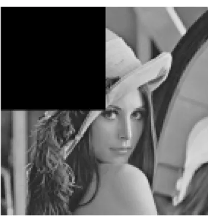
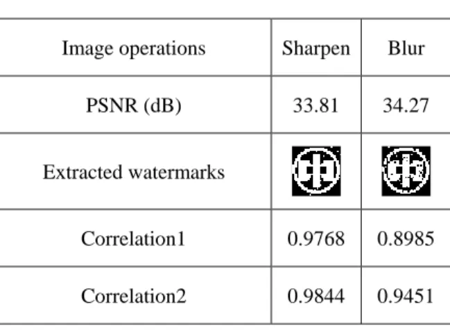
(6) 3.1. The watermarked image is scaled to its half. JPEG/JPEG 2000 Loosy Compression JPEG and JPEG 2000 compression stan-. size in both dimensions and then rescaled to its. dards are used to examine the robustness of the. original size. Table 5 shows that the extracted. watermark. When quality factor (QF) is low, it. result is still visually recognizable.. means the compression ratio is high with less. 4. CONCLUSIONS. image fidelity. We use JPEG and JPEG 2000 compression under different QF on the watermarked image, respectively. The extracted. This paper has presented a novel algorithm. results are depicted in Table 1 and Table 2.. for embedding two watermarks into the image. From the simulation results, we can claim that. with private and public watermarking at a time.. the method performs best resistance to these. This algorithm reduces noticeable artifacts by. two kinds of compression standards.. embedding the watermarks into different mid-. 3.2. dle-frequency subbands of the wavelet trans-. Filtering In general, smoothing and sharpening op-. form. One benefit for the proposed algorithm is. erations are used to enhance the image quality.. that we can embed/extract the two watermarks. These operations are applied to evaluate the. in parallel, especially in large-scale use of wa-. robustness of our algorithm. Table 3 shows the. termarks for copyright protection. Since the. extracted results of applying these operations. two watermarks, a visually distinguishable im-. separately. As can be seen, the extracted wa-. age and a binary random sequence, stand for. termarks are highly similar to the original. In. the original owner’s signature and the buyer’s. general, the proposed method performs better. unique serial number, respectively. This algo-. in sharpening operations than in blurring ones. rithm can be used for the purpose of ownership. under lower PSNR value.. identification and fingerprinting complemen-. 3.3. tarily. Specifically, it would be useful to prove. Cropping Usually, A pirate would try to remove the. in court using public watermarking that a wa-. embedded watermark by cutting some uninter-. termark is present without exhibiting the origi-. esting part of the watermarked image. For ex-. nal image publicly. Furthermore, if necessary,. ample, a quarter of the watermarked image is. we can enhance the authentication by private. cropped, as shown in Fig. 5. Table 4 shows the. watermarking. relationship between the extracted results and. demonstrate that the proposed method has. the cropping ratio. Whether the missing por-. superior performances to common image. tions are filled with zero values or original un-. operations and geometric distortions, and. watermarked images, it is interesting to find out. therefore satisfy the watermarking properties. that the results are the same. Although the ex-. mentioned in the introduction section. With. tracted w1 is degraded linearly as the cropped. these advantages, this algorithm has potential. ratio is increasing, the extracted rate of w2 is. for image copyright protection in digital world.. Simulation. results. Future work will focus on incorporating the. still high. 3.4. therein.. human visual model (HVS) and error correct-. Scaling. 6.
(7) ing codes (ECC) to improve the robustness. Huang, “Hiding digital watermarks using. under some perceptual mask.. multiresolution wavelet transform,” IEEE Transactions on Industrial Electronics,. 5. REFERENCES. vol. 48, no. 5, pp. 875-882, Oct. 2001. [5]. [1]. I. J. Cox, J. Kilian, F. T. Leighton, and T.. watermarks in images,” IEEE Transac-. Shamoon, “Secure spread spectrum wa-. tions on Image Processing, vol. 8, no. 1,. termarking. pp. 58 -68, Jan. 1999.. for. multimedia,”. IEEE [6]. Transactions on Image Processing, vol. 6,. [2]. H.-C. Huang, F.-H. Wang, and J.-S. Pan,. no. 12, pp. 1673-1687, Dec. 1997.. “A VQ-based robust multi-watermarking. I. J. Cox, and M. L. Miller, “The first 50. algorithm,”. years. Fundaments, vol. E85-A, no. 7, pp.. of. electronic. watermarking,”. IEICE. Transactions. [7]. Processing, vol. 2002, no. 2, Feb. 2002,. S.-J. Lee and S.-H. Jung, “A survey of. pp. 126–132.. watermarking techniques applied to mul-. I. Hong, I. Kim, and S.-S. Han, “A blind. timedia,” Proceedings of IEEE Interna-. watermarking technique using wavelet. tional Symposium on Industrial Elec-. transform,” Proceedings of the IEEE In-. tronics, vol. 1, 2001, pp. 272–277.. ternational Symposium on Industrial Electronics, vol. 3, 2001, pp. 1946–1950. [4]. on. 1719-1726, July 2002.. EURASIP Journal on Applied Signal. [3]. C.-T. Hsu and J.-L. Wu, “Hidden digital. M.-S. Hsieh, D.-C. Tseng, and Y.-H.. □. LL3 HL3. HL2 LH3 HH3. HL3 HH2. LH2. Original image. DWT. LH3. HH3. Fig. 1. Three-level DWT hierarchical decomposition of an image.. 7.
(8) Original Image Three Level DWT. Map, Scramble, Expand, and Embed. w1 Binary Watermark Image. Subband LH3. Other subbands. Embedded LH3. Modulate. Random Positions. Generate. Binary Random Sequence. Subband HL3. w2. Embedded HL3. IDWT Watermarked Image. Fig. 2. The block diagram for embedding two watermarks.. Original Image. Watermarked Image. w2. Three Level DWT. Three Level DWT Subband LH3. Embedded HL3. Extract. Embedded LH3. Extract. w1 Binary Watermark Image. Fig. 3. The block diagram for extracting two watermarks.. 8. Binary Random Sequence.
(9) (a). (b). Correlation1=1 Correlation2=1 (d) (c) Fig. 4. Example of the proposed watermarking approach. (a) Original gray level image Lena of size 512 by 512. (b) Watermark w1 of size 32 by 32. (c) Image with embedded watermarks w1 and w2 (PSNR 46.55 dB). (d) The extracted watermarks with no attacks.. Fig. 5. Quarter of the embedded image is missing.. Table 1.. Changes of measures and extracted watermarks under various JPEG quality factors. QF (%). 100. 50. 30. PSNR (dB). 42.66. 35.03. 33.7. Extracted watermarks Correlation1. 1. 0.9706 0.8650. Correlation2. 1. 0.8751 0.7513. 9.
(10) Table 2.. Changes of measures and extracted watermarks under various JPEG 2000 quality factors. QF (%). 100. 80. 60. PSNR (dB). 44.65. 37.65. 37.05. Extracted watermarks Correlation1. 1. Correlation2. Table 3.. 0.8495 0.6865. 0.9765 0.8437 0.7900. Results of filtering.. Image operations. Sharpen. Blur. PSNR (dB). 33.81. 34.27. Correlation1. 0.9768. 0.8985. Correlation2. 0.9844. 0.9451. Extracted watermarks. Table 4.. Results of cropping.. Remaining part 89.7% 79.8% 75.0% 69.7% 60.0% 50.0% 39.6% 29.5% 20.0%. 9.9%. Extracted watermarks Correlation1 0.8723 0.8022 0.7439 0.7255 0.6280 0.5525 0.4745 0.4235 0.3533 0.2517 Correlation2 0.9922. 1. 1. Table 5.. 1. 0.9844. 1. Robustness to scaling attack. PSNR. 32.93. Extracted watermark Correlation1. 0.8637. Correlation2. 0.9611. 10. 1. 1. 1. 1.
(11)
數據
相關文件
image processing, visualization and interaction modules can be combined to complex image processing networks using a graphical
Promote project learning, mathematical modeling, and problem-based learning to strengthen the ability to integrate and apply knowledge and skills, and make. calculated
Now, nearly all of the current flows through wire S since it has a much lower resistance than the light bulb. The light bulb does not glow because the current flowing through it
Courtesy: Ned Wright’s Cosmology Page Burles, Nolette & Turner, 1999?. Total Mass Density
These are quite light states with masses in the 10 GeV to 20 GeV range and they have very small Yukawa couplings (implying that higgs to higgs pair chain decays are probable)..
Light rays start from pixels B(s, t) in the background image, interact with the foreground object and finally reach pixel C(x, y) in the recorded image plane. The goal of environment
(It is also acceptable to have either just an image region or just a text region.) The layout and ordering of the slides is specified in a language called SMIL.. SMIL is covered in
A digital color image which contains guide-tile and non-guide-tile areas is used as the input of the proposed system.. In RGB model, color images are very sensitive
