Efficient hybrid tree/linear array architectures for
block-matching motion estimation algorithms
M.-J.Chen L.-G. Chen K.-N.Cheng M.C.Chen
Indexing terms: Motion estimation, Videoconferencing, Video coding
Abstract: Execution latency and I/O bandwidth play essential roles in determining the effectiveness and the cost of a parallel hardware implementation for block-matching motion estimation algorithms. Unfortunately, almost all traditional architecture designs, e.g. the two- dimensional mesh-connected systolic array architecture (2DMCSA), and the tree-type structure (TTS), fail to take these two factors into account simultaneously. As a result, they s8uffer from either large execution latency or huge input bandwidth requirements. The authors propose a family of t r e e h e a r architectures, which efficiently optimise the total implementation cost by combining the merits of the 2DMCSA and the TTS. Moreover, to facilitate hardware designs, the authors present the tree-cut techniques and the on-chip buffer design method to meet computational demands of various video compression applications. Since the proposed architectures are capable of executing the exhaustive search and the fast search block- matching algorithms, they offer relatively flexible and cost-effective hardware solutions for a wide range of video coding systems, including CD- ROM, portable visual communications systems and high-definition TV.
1 Introduction
During recent years the vigorous growth of personal computers together with the rapid progress of digital communications technologies have spurred the evolu- tion in transforming information into a digital format. A digital representation of signals has advantages over its analogue counterpart in terms of noise irnmunity and signal processing feasibility. Consequently, it pro- 0 IEE, 1996
IEE Proceedings online no. 19960541
Paper first received 6th November 1995 and in revised form 9th April 1996
M.-J. Chen, L.-G. Chen and K.-N. Cheng are with the Department of Electrical Engineering, National Taiwan University, Taipei, Taiwan 10764, Republic of China
M.C. Chen is with the Department of Electrical Engineering, University of California, Los Angeles, CA 90024, USA
IEE Proc.-Vis. Image Signal Process., Vol. 143, No. 4, August 1996
vides considerable leverage of signal quality for stor- age, transmission, and duplication. However, the obvious disadvantage of such approach is that the size of data becomes several orders larger. To economically utilise limited communications networks and storage resources, it is necessary for digital imagehide0 appli- cations to employ data compression techniques. Several video coding standards, such as ITU CCITT H.261 [l], H.263 [2] standards, and MPEG [3-61 standards, have been developed to provide a platform for interportabil- ity. Because the removal of temporal redundancy between successive image frames relies heavily on the use of a block-matching motion estimation technique, the design of a block-matching motion estimation algo- rithm and its corresponding hardware structure consid- erably affect the performance and the cost of a video coding system.
Among various block-matching algorithms, the 2-D full search (or exhaustive search) method (2DFS) dom- inates most parallel hardware implementations [7-1 I] because of a high degree of regularity in its memory accesses and computations. However, a massive com- putational effort is usually needed even for the applica- tions with a moderate frame rate and a medium frame size. For instance, it requires over 778 million subtract/ accumulate operations and 1,557 million data accesses per second to perform the 2DFS algorithm with a search range -8 to 7 and a block size of 16 x 16 for a standard videoconferencing image sequence (352 lines x 288 pixelsiline x 30 frameshec). For the applications where power consumption and processing speed are critical, it is clear that trading-off estimation perform- ance with computation complexity is necessary.
In the past, various fast search algorithms [13-181 have been proposed to alleviate the computational bur- den imposed by the 2DFS method. Basically the major- ity of these fast search algorithms reduce the number of searched positions largely based on the assumption that the mean-absolute-error (MAE) between the current- frame block and the previous-frame search candidate increases monotonically as the search position moves away from the best match position. Consequently, compared to the 2DFS, they usually place more serious demands on the supporting memory systems since rather flexible data access patterns are needed. Moreo- ver, since the distance between each consecutive search position often varies with the search step, e.g. the three-step hierarchical algorithm, it is difficult to take advantage of interblock data dependency to reduce input bandwidth.
Recently, we presented the one-dimensional full search algorithm (1DFS) [19]. The method distin- guishes itself from other fast algorithms by the fact that it maintains the regularity of the 2DFS scheme while an effective tradeoff between computational complexity and estimation accuracy is achieved. This attractive feature makes it possible to optimise input bandwidth without resorting to a sophisticated control scheme for the scheduling of memory access activities. Intuitively, parallel architectures for the 2DFS can be modified slightly to implement the l D F S algorithm. Unfortu- nately, the lDFS method, like most other fast search algorithms, also falls into the hierarchical search cate- gory. Thus, low execution latency is desirable since the nth step search process cannot start before the search result of the (n-1)th step search process is readily avail- able. Although using block-level interleaving [ 121 can eliminate the waiting cycle for a massive pipeline struc- ture, the higher the execution latency that an architec- ture possesses, the more the segmented image blocks are interleaved. As a result the hardware overheads in arranging and buffering input data, generally dictated by the execution latency of an architecture, can become exceedingly high if conventional systolic array architec- tures are used.
For parallel implementations of block-matching algo- rithms most current designs can be broadly classified as the 2DMCSA [9] and the TTS [12]. The 2DMCSA exploits data dependency between each consecutive search position by properly inserting data-skew regis- ters into the processing element array based on a pre- determined time schedule and a systematic projection method [20]. Though a minimum amount of input bandwidth is achieved, it leads to huge execution latency since the final results can only be obtained after the computations travel through a long propagation path. On the other hand, the TTS conducts the compu- tations of each displaced candidate in an as-soon-as- possible (ASAP) fashion such that the execution latency is greatly optimised. Since no-data skew is allowed, image pixels associated with a displaced candi- date have to be accessed simultaneously to ensure high utilisation of processing elements (PES). However, the input pin-count increases rather rapidly as more PES are integrated into a chip [Note 11, thereby making the structure impractical whenever the target applications demand large numbers of PES. To keep input band- width under a reasonable number while minimising execution latency, our effort is to investigate various possibilities in combining the appealing attributes of these two architectures.
2 2DFS and 1 DFS block-matching algorithms
For the block-matching motion estimation a current- frame image from a video sequence is divided into blocks with a size of N x N . Then, for a maximum motion displacement of p pels, each segmented block is compared with the displaced candidate blocks in the previous frame within a (N+2p) x (N+2p) square- shaped search window. A two-dimensional motion vec- Note 1: Although data sharing between two consecutive search blocks can be used to reduce input bandwidth, in practice, the scheme is rarely adopted owing to the fact that a quite large hardware overhead is necessary to handle the situation when the search process proceeds to a new row or column of search candidates. Consequently, we assume that no interblock data dependency is exploited for the 7 T S in our discussion.
tor is selected for each block such that the distortion resulting from a block-matching motion compensation scheme is minimised.
The straightforward search scheme is the 2DFS where the distortion corresponding to all (2p+ 1)2 can- didates within a search area are calculated and com- pared. The optimal motion vector is chosen by selecting the search position that gives the lowest dis- tortion. Usually, the MAE criterion, defined by eqn. 1, is favoured against the mean-square-error criterion owing to its simplicity and computational efficiency for implementations.
(1)
where Xk(m, n) is the pixel value at the position (m, n) in the frame k . Instead of examining all candidates within a two-dimensional search window, the lDFS method adopts a coarse-to-fine search procedure. Cen- tred at (0, 0), the lDFS first searches through all dis- placed candidates along one co-ordinate, e.g. the horizontal dimension, to find the position having the minimum distortion. Based on this result the lDFS in a similar manner manages to locate the best match position in another co-ordinate, e.g. the vertical dimen- sion. The best match from the first step becomes the initial displacement for the current block. Centred at this initial displacement, the search procedure repeats with a halved search range. Then the motion vector is determined. To illustrate clearly the lDFS algorithm, a graphical representation of the search procedures is shown in Fig. 1. As can be seen, the lDFS preserves the natural dataflow of the 2DFS; therefore it provides an opportunity in exploiting inter-block data depend- ency to reduce input bandwidth as compared to other fast search schemes. Since the IDFS and the 2DFS methods are similar in their search characteristics, it is possible to design parallel architectures that can imple- ment them efficiently.
-7 -6 -5 -4 -3 -2 -1 0 1 2 3 4 5 6 7
Fig. 1
Search range -7 to +7
Motion vector = (3, 6)
Illustration of one-dimensional full seavch algovithm
3 Two-dimensional mesh-connected systolic array structures and tree-type architectures
The 2DMCSA is originally derived from projecting the four-dimensional dataflow graph (DG) onto a two- dimensional plane. With an appropriate time schedule, the computations can be executed in a massive pipe- lined parallel structure without any idle cycle while only a small number of input is supplied. To illustrate the design procedure, Fig. 2 shows the three-dimen- sional DG of the 2DFS algorithm with the time sched- ule vector (m, i,j) equal to (2, 1, 1). Based on the three- dimensional DG, the two-dimensional systolic architec- ture ( N = 4 and p = 2) of Fig. 3 is derived by the m-
and j-plane projection, respectively. For brevity, here we assume that all pixels of a 4 x 4 current-frame block is preloaded into the individual PE. According to the time scheduling, these PES perform the operations of absolute pixel difference between the current block pix- els and the search window pixels concurrently. Then, these absolute differences are accumulated with the partial sums provided by the adjacent (upper) PES. After four clock cycles, the partial sum correslponding to each column of the displaced candidates begins to shift to the linear adder array. The MAE of the dis- placed candidate is obtained at the end of the adder array with eight cycles of delay. These MAE values then enter the motion vector selection unit (M), and the corresponding motion vector is determined.
m
T i
Fig.2 3-0 dataflow graph of 2DFS algorithm with time schedule vector of (2, 1, 1 ) 0 0 0 0 61 5721
jl-5
I I 5$23222 12; I ,'133323 13; I I I I I '44324 14 1 L - - - _ / 0Fig.3 2-0 mesh-connected systolic array structure with N = 4
The tree-type array architecture decomploses the computations into two sections, where the subtract/ absolute section (D) calculates the absolute pixels dif- ferences and the accumulate section (A) computes the sums of the absolute differences to obtain the MAE. IEE ProcVis. Image Signal Process., Vol. 143, No 4, August 1996
As shown in Fig. 4, the two-dimensional subtractiabso- lute DG of the 2DMCSA is recorded into a one-dimen- sional linear array, whereas the two-dimensional accumulate section is transformed into a tree-type array in order to minimise the number of accumulation stages. The major difference between this approach and the 2DMCSA is the need to access N2 search area data in parallel. Because the absolute differences corre- sponding to a reference block are calculated simultane- ously within a PE array and they are accumulated in a tree manner, the theoretical shortest propagation path is acheived while the maximal input bandwidth require- ment is incurred. 20 21 22 23 30 31 32 33 40 41 42 43 50 51 52 53 10 1 1 12 13 20 21 22 23 30 31 32 33 40 41 42 43 00 01 02 03 10 1 1 12 13 20 21 22 23 30 31 32 33
r
x k'9
l-
Fig.4 Tree-type array architecture with N = 44 Hybrid tree/linear architectures
It is clear that the tree-style computation has an advan- tage in optimising execution latency. On the other hand, the systolic dataflow projection offers a powerful means in maximising on-chip data reusage. Therefore a hybrid architecture that adopts these desired character- istics in the design can potentially provide better trade- offs with respect to the implementations targeting at the 2DFS and lDFS algorithms.
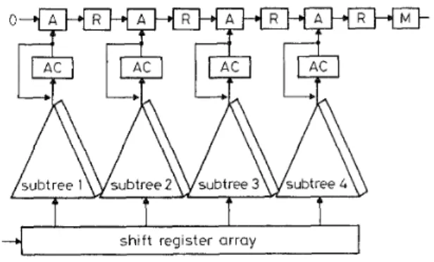
The hybrid t r e e h e a r architecture can be viewed as a combination of the tree architecture and the systolic architecture. With respect to the design of the hybrid structure, the tree technique is restricted to the compu- tations corresponding to each M columns ( M is smaller than or equal to N), whereas the systolic mapping method is applied to the accumulation process of the partial sums produced by these sub-trees. Conse- quently, the hybrid structure has a one-dimensional MN-PE subtree array designated for calculating the absolute differences and a linear adder array responsi- ble for accumulating the partial sums to get the final result. To make our design procedure clear, each sub- tree and its associated inputs can be considered as a supernode and superset input, respectively. If we repre- sent the 2DFS D G using supernodes and superset inputs, the original four-dimensional DG can be trans-
formed into a three-dimensional DG. Again, by pro-
jecting the D G onto m-plane, a one-dimensional systolic array, as shown in Fig. 5, consisting of subtrees and parallel pel inputs is obtained.
(suDerset I nDut1
0
U Fig.5 Hybrid tree/lineur architecture with N = 4 and A4 = I
Basically, the TTS and the 2DMCSA are the two special cases of the hybrid structure, where A 4 is equal to N for the TTS while the 2DMCSA degenerates the adder subtree to a single adder. Since both latency and input bandwidth can have strong impacts on the cost of a single-chip implementation, the hybrid structure is capable of efficiently controlling these two factors by choosing an appropriate size of the subtrees.
Table 1 compares number of adders, execution latency, input pin count, number of processing cycles, and flexibility of various architectures. As expected, the TTS has the shortest execution latency, which is on the logarithmic order of the PE number. But it also demands the most in the aspect of input bandwidth. However, the structure has the most flexibility since there exists the least amount of constraint on how the data should proceed within the PE array. Conse- quently, a wide variety of block-matching algorithms, including the 1 DFS, the three-step hierarchical search, and the 2DFS, can be implemented. In contrast, the only algorithm that is suitable for the 2DMCSA is the 2DFS because the large control overhead incurred by its huge execution latency can easily prevent any hierar- chical fast algorithms from being efficiently imple- mented. The hybrid architecture, on the other hand, tradeoffs latency with input bandwidth. By varying M , the hybrid structure can control execution latency and input bandwidth so that a single-chip design with rea- sonable 110 pin count and control overhead can be realised.
4. I Tree-cut techniques
Since a significant amount of inherent parallelism is available in the block-matching algorithms, parallel processing techniques can be extensively employed to speedup the estimation process. The cost of the imple- mentation, however, depends strongly on the number of PES integrated into a single chip. Therefore for most applications where a moderate computational power is needed, the use of hardware timesharing provides a superior solution. The choices of the PE reduction are made between the number of the subtrees and the number of PES in the subtrees. In general, execution latency is mainly determined by the number of the sub- trees, while input pin count relies heavily on the number of the PES in the subtree. Because input band- width usually creates a more serious problem for a single-chip implementation, our discussions here are
restricted to the tree-cut techniques for reducing the number of PES within each subtree. Nevertheless, the choice between the two factors is not exclusive. In fact, a better system’s cost evaluation should take both two factors into consideration.
In the following, the hardware timesharing with a factor of two is assumed in our examples to show the various hardware impacts from two different schedul- ing techniques. Furthermore, we use the name of degenerated subtree for the subtree under a PES reduc- tion to distinguish it from the original subtree. 4.
I.
1 Direct form: For the direct form approach, the absolute differences of each original subtree are decomposed into two independent parts, i.e. the even part and the odd part, as defined in eqn. 2 according to the n index.1
MAE(^,^) =
S U M e v e n ( m ) =
SUModd(m)= IXk(m, 2n) -Xk-l(rn+i, 2n+l+j)l
C
( S U M e v e n ( m )+
~ ~ ~ o d d ( r n ) ) (2) m=0 IXk(rn,2TL) - Xk-l(rn + 2 , 2 n + j ) l N - 1 n = O 2-1 7l=OThe computations of these even and odd partial sums are then interleaved within the degenerated subtrees. Since it takes two cycles to obtain the partial sums of the original subtrees, an accumulator and a recursive loop have to be appended to the degenerated subtree’s outputs such that the even and odd partial sums can be accumulated before they are shifted to the linear adder array. Moreover, the switches that control connections between the accumulators and the linear adder array are essential to ensure a proper function. Fig. 6 shows the block diagram of the structure with a direct form scheduling and a block size of 4 x 4, where the over- heads for the hardware interleaving are four additional accumulators, registers and switches.
shift register array
1
Fig. 6uling Block diagram of UZ-cut hybrid structure with direct form sched- 4.1.2 Modified form: Compared to the direct form approach, the modified form scheme schedules the computations in a way that the odd partial sums and Table 1: Comparisons of various block-matching architectures
Architecture Area Latency Cycle required Input Flexibility
type (adder) (cycle) (2DFS) (word) (BMA)
ZDMCSA 2 N L + N + 1 3 N + 1 (2p + NH2p + 1 ) N 2DFS TTS 2 N z 21ogN+2 (2p + I ) 2 l\p all
Hybrid 2 W t M logNM + 2 1 + 2 (2p t 2#(2p + 1 ) NM 1 DFS & 2DFS
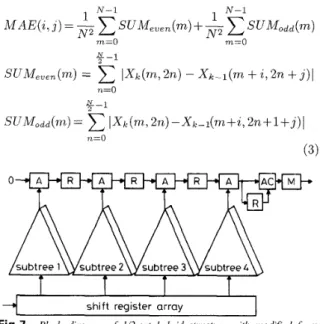
the even partial sums are calculated independently before they are finally accumulated at the output of the linear array as depicted by eqn. 3. Because the accumu- lations between the odd and even partial sums are moved to the output of the linear array, the hardware overheads are minimised to only one accumulator, recursive loop, and switch, as shown in Fig. 7.
~ N-1
I I I I
shift register array Fig.7
scheduling Block diagrum of 1/2-cut hybrid structure with modijed form
5 design
The use of parallel processing significantly enhances the computational capability of a single chip. The chal- lenge, however, lies in the design of the memory system that can sustain a continuous flow of data from mem- ory to processing array without incurring large over- heads. Two important schemes, namely: memory interleaving, and on-chip buffering, are employed in the system for the external and internal data accesses, respectively.
Memory interleaving and on-chip buffer
5,
I
Memory interleavingThe key to ensure that the computational power of the hybrid structure can be fully utilised is to meet the bandwidth requirements imposed by the processing ele- ment array. Provided each memory module can per- form at most one read operation per clock cycle, the number of memory modules has to match the number of PES in the subtree, i.e. the number of input ports, to keep all the PES busy. In addition, due to the rather random characteristics in the data access of the lDFS algorithm, the distribution of the image pixels has to be done in a way that the adjacent N image pixells can be read simultaneously on each clock cycle, where N rep- resents the number of input ports. One way to achieve the goal is to allocate each N horizontal or vertical adjacent image pixels to different memory modules. Let
Xj-,(i, j ) represent the previous-frame pixel value at index (i, j ) and let MM(i, j ) denote the memory module that Xk-*(z', j ) resides. Then the assignment of
Xt-l(i,
j ) to N memory modules can be formalised as follows: To exemplify this memory interleaving scheme, Fig. 8 shows the pel distribution for a block size of 4 x 4, M M ( i , j ) = (i+
j ) modulo N (4)where the numbers indicate the memory modules that the image pixels are allocated. As can be seen, every four consecutive pels always reside on four independent memory modules both horizontally and vertically. Thus, it can provide an efficient data access of either N
rows or columns of data simultaneously. In this way, the horizontal search and the vertical search of the lDFS can be executed successfully.
0 1 2 3 0 1 2 3 0 1
11 2 3 01 1 2 3 0 1 2
2 3 0 1 2 2 0 1 2 3
3-10 1 2 3 0
Fig. 8 Image pel distribution for memory interleaving
I I 1 I
& & & & & & & z
mux mux mux mux
1
"
1
1
'\
1
modified from 112 tree-cut processor array
~ ~~
Fig.9
cut array Block diugrum of shift register array for modij?ed form 1/2 tree-
5.2 On-chip buffer design
The on-chip buffer maximises the data reusage, thereby relieving the heavy input and memory bandwidth demands placed by the parallel processing elements. To realise the desired dataflow of the hybrid structure, a parallel-in-parallel-out shift register array is used. Unlike the 2DMCSA, each shift register array is com- posed of N words of shift registers, as shown in Fig. 9. At each clock cycle, new N parallel input data are sequentially shifted into the shift register array and are shifted out after N clock cycles. For the li2-cut hybrid structure with either the direct form or the modified form scheduling, the shift register based on-chip buffer is modified to adjust to the changes of the desired data- flow regarding the hardware time-multiplexing. Refer- ring to Fig. 9, the N-word shift registers are split into two Ni2-word shift registers, where the one holds the odd part inputs and the other is responsible for the even part inputs. By toggling the multiplexers, the inputs of the degenerated array are selected from one of the two shift register arrays.
6 Single chip design
The li2-cut hybrid structure with the modified form scheduling has been designed under 0.8 CMOS technology using Magic. Its functionality has been ver- ified by Verilog. Fig. 10 shows the chip layout, which requires 97 active signal pads and contains 16 8-PE
degenerated subtrees in a die size of 12.0 x 4.3 mil2. According to SPICE simulations, it is functional up to 30MHz, or 33.3ns per cycle. It is sufficient to meet the IEE Proc.-Vis. Image Signal Process., Vol. 143, No. 4, August 1996 22 1
Fig. 10 Chip luyout ofIL-cut hybrid treehear array architecture
specifications for the real-time processing of the 2DFS algorithm for videoconferencing and videophony appli- cations, and the lDFS algorithm for the NTSC and HDTV applications. The characteristics of the chip are summarised in Table 2.
Table 2: Characteristics of motion estimation chip
Technology 0.8pm CMOS
Chip size 12.0 x 4.3mm
Chip clock 30MHz
Number of pads 97
7 Conclusions
We have proposed a family of hybrid t r e e h e a r archi- tectures and their corresponding memory structures for the lDFS and 2DFS block-matching motion estima- tion algorithms. Targeting at the joint optimisation of execution latency and input bandwidth, we have shown that by combining the tree technique and the systolic mapping method the proposed architectures potentially provided a superior design in reducing implementation costs in terms of the memory system’s complexity, I/O pin count, and the control overhead in buffering/ arranging input data. To allow a flexible internal and external data access we have designed an effective memory structure using the memory interleaving and the on-chip buffer schemes. Furthermore, we presented the tree-cut techniques that enabled an efficient time- sharing of the hardware and simultaneously reduced input bandwidth. Finally, a single-chip circuit imple- mentation using the 1/2-cut technique demonstrated the versatility and effectiveness of our proposed hybrid architectures.
8 References
1 CCITT Study Group XV: ‘Draft revision of recommendation H.261 - video codec for audio visual services at px64kbps’. Temporary document 5-E, July 1990
2 ITU-T Recommendation H.263: ‘Video coding for low bitrate communications’. (Draft), July 1995
3 LEGALL, D.J.: ‘MPEG: A video compression standard for mul- timedia applications’, Commun. ACM, 1991, 34, pp. 46-58
4 ISO/IEC 1172-2: ‘Information technology--coding of moving pic- ture and associated audio for digital storage media at up to about
1.5 Mbit/s: part 2 video’. August 1993
5 ARAVIND, R.: ‘Image and video coding standards’, AT&T
Tech. J., 1993, 12, pp. 67-89.
6 SCHAFER, R., and SIKORA, T.: ‘Digital video coding stand- ards and their role in video communications’, Proc. IEEE, 1995, 83, pp. 907-924
7 YANG, K.-M., SUN, M.-T., and WU, L.: ‘A family of VLSI designs for the motion compensation block-matching algorithm’,
IEEE Trans., 1989, CAS-36, pp. 1317-1325
VOS, L., and STEGHERR, M.: ‘Parameterizable VLSI architec- tures for the full-search block-matching algorithm’, IEEE Trans.,
9 KOMAREK, T., and PIRSCH, P.: ‘Array architectures for block-matching algorithms’, IEEE Trans., 1989, CAS-36, pp.
1301-1308
10 RUETZ, P.A.: ‘A high-performance full-motion video compres- sion chip set’, IEEE Trans. Circuits Syst. Video Technol., 1992, 2,
pp. 111-122
1 1 ISHIHARA, K.: ‘A half-pel precision MPEG2 motion-estimation processor with concurrent three-vector search’. ISSCC digest of technical papers, 1995, pp. 286-287
2 JEHNG, Y . - S . , CHEN, L.-G., and CHIUEH, T.-Z.: ‘An efficient and simple VLSI tree architecture for motion estimation algo- rithms’, IEEE Trans. Circuits Syst. Video Technol., 1993, 41, pp. 889-899.
3 JAIN, J.R., and JAIN, A.K.: ‘Displacement estimation and its application in interframe image coding’, IEEE Trans., 1981,
4 KOGA. J.: ‘Motion compensated interframe coding for video conferencing’. Proceedings of National Telecommunications con- ference, 1981, pp. G5.3.1-5.3.5
5 SRINIVASAN, R., and RAO, K.R.: ‘Motion predictive inter- frame coding’, IEEE Trans., 1985, COM-33, pp. 1011-1015 6 LI, R., and LIOU, M.L.: ‘A new three-step search algorithm for
block motion estimation’, IEEE Trans. Circuits Syst. Video Tech- nol., 1994, 4, pp. 438442
7 JONG, H.-M., CHEN, L.-G., and CHIUEH, T.-D.: ‘Accuracy improvement cost reduction of 3-step search block matching algo- rithm for video coding’, IEEE Trans. Circuits Syst. Video Tech- nol., 1994, 4, pp. 88-90
18 CHEN, M.C., and WILLSON, A.N.: ‘A high accuracy predictive logarithmic motion estimation algorithm for video coding’. Pro- ceedings of international symposium on Circuits and systems,
May 1995, Vol. 1, pp. 617-620
19 CHEN, M.-J., and CHEN, L.-G.: ‘One-dimensional full search motion estimation algorithm for video coding’, IEEE Trans. Cir- cuits Svst. Video Technol., 1994, 4, pp. 504-509
8
1989, CAS-36, pp. 1309-1316
COM-29, pp. 1799-1808
20 KUNG, S.Y.: ‘VLSI array processors’ (Prentice Hall, Englewood Cliffs, NJ, 1988)