Proceedings of the 1998 IEEE
International Conference on Robotics & Automation Leuven, Belgium May 1998
Multi-agent Based Dynamic Scheduling for
a
Flexible Assembly
System
Yung-Yu Chen, Li-Chen Fu and Yu-Chien Chen
Dept. of Computer Science and Information Engineering
National Taiwan University,Taipei ,Taiwan,R.
0.
C
Abstract
This paper proposes a multi-agent based dynamic scheduling approach for a flexible assembly system. We first introduce a flexible control system developed by IntelligentRobotics and Automation Laboratory in National Taiwan University. Based on that control system, the agents can communicate with each other conveniently. A generic agent architecture is proposed to model the pieces of equipment in the flexible as- sembly system. With a distributed architecture, the agents make their scheduling decisions using their lo- cal rule base. The agents acquire the resources follow- ing the distributed resource allocation protocol. The scheduling complexity is reduced to meet the real-time response requirement in the applications for flexible automated production. The present work is applied to the experimental robotized flexible assembly system in the above laboratory.
1
Introduction
A scheduler is called dynamic (on-line) if it makes its scheduling decisions at run time on the basis of the current requests for service. Dynamic schedulers are flexible to adapt to an evolving task scenario and have to consider only actual task requests and execution time parameters [2]. Research on multi-agent systems is mainly concerned with how to coordinate intelligent behavioral activities among a collection of autonomous agents [3]. The work in [3] discusses the negotiation among agents for the allocation of resource with time taken into account.
Jennings [4] detailed the design of the multi-agent structure and discusses the principle of handling er- rors. The work in [5] discusses the rescheduling issue in a decentralized manufacturing system. Manufactur- ing systems with multi-agent modelling can be found in [6, 71. Resolution of real-time conflicts in multi- robot systems appears in [8]. The work in [9] pro- poses some criteria to set up a robotic assembly cell
and analyzes the interaction among multiple robots. Recently, agent-based approach is applied t o robotic assembly environment [6, 7, 12, 13, 141. The work [14] introduces an idea of cooperative action with group organization and a strategy for cooperative task pro- cessing using communication. There is an efficient ne- gotiation algorithm using his proposed groupcast com- munication and a learning mechanism with reference to historical records on the past negotiation.
This paper consists of six sections. Section 2 de- scribes a robotic assembly environment and introduces a general control system for that environment. The scheduling problem to be solved is also defined. Sec- tion 3 introduces an agent architecture and describes
the functionality of the agent’s module. Section 4 de- scribes the strategy for resolving resource contention among agents. Section 5 describes the implementa- tion of the dynamic scheduling for the flexible robotic assembly cell. Section 6 describes the experimental result. Finally, some conclusions are made in Section 7.
2
System Description
In our laboratory, we have a two-robot assembly system that is dedicated to assemble various types of mechanical parts sent serially into the conveyor belt by the part loader. There are two products currently assembled in this system, and each product has four parts that are assembled by the robot manipulator. The operations include vertical insertion, horizontal insertion, and rotation in assembling with the sub- assembly fixed at the assembly sites. The parts are fed into the system without a specific order, and the scheduling is made on-line. We proposed a rule based dynamic scheduling approach t o schedule for the whole assembly system [17].
The cell is equipped with several pieces of hard- ware that work together to assemble parts. The brief description is given below:
R o b o t : There are two robots in the system, namely ADEPT and C R S . Each of them is equipped with an automatic tool changer(A"I'C) in order t o assemle different types of mechanical products. Each robot has a mounted CCD camera which serves the high-precision localization OF the part. Also, each robot has its own form-torque sensor that can be used t o correct the measure- ment error during assembly.
0 Part Loader: It is composed of a Carte.,' <'Ian ma-
nipulator and a pallet that holds the parts walking to be assembled. The Cartesian manipulator will pick up the parts from the pallete and put it on the coveyor belt.
0 CCD C a m e r a : We have one overhead CCD
camera that can determine the type and orien- tation of the incoming part on the conveyor lbelt. Two Eye-In-Hand cameras are mounted on the robots, respectively.
0 Conveyor B e l t : It is responsible for carrying
parts from outside into the cell.
0 R o t a r y Buffer: This is used to temporarily store
the incoming parts that are not suitable for imme- diate assembly. Both robots can access the buffer, but only one robot can be served at one time.
0 P r o x i m i t y Sensors: These are t o detect the
moving speed of each arriving part and act a8 an- chors for the pick-up operation.
Based on the control kernal EMFAK [19], we can easily integrate the different pieces of euipnient to- gether. The scheduling problem is to provide a quick response and safety guarantee for the working pieces of equipment. We model each equipment as an agent. An agent has its own capability and thus the scheduling can be viewed as a group of schedulers working simu- taneously. This is a distributed system architechre. The coordination among agents is crucial in making the entire system running smoothly.
3
Agent Architecture
There are different kinds of agents in the robotic assembly cell. They can communicate with each other through the communication center EMFAK [:19]. Fig
1 shows the layout of the multi-agent based system. Each agent is composed of two main processes which are manager process and controller process. A con- troller process is related to the domain level system,
C I c
i
Figure 1: Muti-agent architecture
Figure 2: The agent architecture
which includes comimunication interface module and domain level controller module. Communication in- terface module is responsible for protocol conversion if controller moudule does not support the pre-selected communication prottocol.
On the other hand, manager process is responsible for making the socid contact with other agents and scheduling the local tasks. Its objective is t o ensure that the agent's domain level activities are coordinated with the other agent and that its associated hardware runs efficiently.
The agent architelcture is shown in Fig 2. The com- ponents of the generic agent architecture is described in the following sections.
3.1 Cooperatioln
Module
This is an entity that handles the agent-to-agent coordination through message exchange.
It
is respon- sible for inter-agent communication. This module has two functional roles:Message processing :Since this module is directly con- nected t o EMFAK, it is responsible for sending message on behalf of the agent and receiving mes- sage from the other one.
Coordination In the later section, the distributed re- source allocatioin protocol will be described. Re- source contention is the motivation for agent co-
ordination. The agent’s scheduler module is con- centrated on making its local scheduling and de- pends on the cooperation module if it is in need of a resource managed by the other agent.
3.2 Scheduler Module
The function role of the scheduler module is to keep the controlled equipment working efficiently, and it will focus on the local affairs. If there is a need of the information or resource from the other agent, it will pass the request t o the cooperation module t o serve for it.
The agent has a degree of autonomy to make its scheduling decisions. We can view the scheduling problem as a single agent problem virtually. This is a divide-and-conquer approach, and scheduling becomes easier. The scheduler module searches for possible next moves with its local state taken into considera- tion, and it uses the cooperation module to cooperate with the other agent.
3.3 Monitor Module
This module is t o monitor the status of tasks sub- mitted from the scheduler module. It must detect whether the controller module finishes its work on time. Thus, a time-out mechanism is used to assure that the link between two components is active. There are two links in this architecture. They are the link between EMFAK and manager process and the link between manager process and controller process, re- spectively. For the link between EMFAK and manager process, the manager process periodically informs EM- FAK of its liveness. EMFAK keeps a timer that is reset whenever EMFAK receives the liveness message. On the other hand, the other link is treated in another way. With the aid of the monitor module, the sched- uler module can make decisions while the underlying domain level system is executing.
3.4 Communication Interface
It serves as the protocol conversion module that can translate different, communication media into a pre- selected protocol. Currently we adopt TCP/IP as our standard protocol [20, 211. In order t o integrate dif- ferent types of equipment, there should be a selected protocol for communication. If the underlying equip- ment does not follow that, the communication inter- face module will be a translator.
3.5 Domain Level Controller System
It is the actual task execution unit that waits for task given from the scheduler and then executes it. For
example, they are programs that control robot move- ment or buffer rotation, etc. Domain level controller system directly controls the physical device. It is the entity that is dedicated t o serve the request from the manager process. Basically, it possesses less intelli- gence and may be seen as a server that receives re- quests and offers the coresponding service.
4
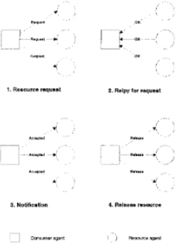
Distributed Resource Allocation ProtocolIn a decentralized environment, the resource allo- cation problem is complicated. We must consider the mutual exclusion problem when multiple agents want to access t o the same resources. There should be a protocol to resolve the conflict on resource. Follow- ing the agent’s architecture, the resource agent uses its manager process to allocate the resource. For clar- ity of discussion, the agent that needs the resources is mentioned as consumer agent. The consumer agent must get all the permission of all its required resources before utilizing them. Each consumer agent has its own priority that the resource agent uses t o decide the precedence of the resource usage.
The consumer agent first sends requests to all relevent resource agents and the resource agent fol- lows a decentralized protocol t o allocate the resource. The resource agent has a request list that keeps the incoming request for the consumer agents. This pro- tocol allows the consumer agent t o try using mutiple resources a t one request. The following sections intro- duce the distributed resource allocation protocol. The consumer agent executes the following protocol:
1. Send request messages to all needed resource agents.
2. Wait for each resource agents t o respond with the
status of reply.
(a) If any reply is REJECT, GOTO 3.
(b) If all replies are OK, GOTO 5.
3 . Send all other resources an REJECTED message. The rejected agent’s request will be removed from all resources’ lists.
4. GOTO 1. (Try again)
5. Inform all resource agents that it is allowed to use the resources.
(send the ACCEPTED messages to the resource agents)
-1
*'.*.d e1
, s...
.I A i l . . , . d se.... i ,Figure 3: Distributed resource allocation protocol( 1)
7. Release all resources.(Send RELEASE messages to resource agents)
The resource agent uses the following rules to make decision:
1. Reject all requests(send a REJECT message) when there is a request of higher priority already en- queued in the list or when the resource it! busy. Otherwise, add the accepted request at th.e rear of the list.
2. Upon receipt of an REJECTED message, remove the sender's request from the list.
3. Send an OK message t o the owner of the first te- quest in the list or the owner of any request that is promoted to the front of the list when the requests in front of it is removed.
4. Upon receipt of an ACCEPTED message, send R,E- JECT messages to the owner of all other requests in the list, empty the list, and mark the resource as busy.
5. Upon receipt of a RELEASE message, mark the resource as free.
Fig 3 illustrates the case that the consumer agent
will get the resources it needs. In the first step, the consumer agent sends requests to all relevant resource agents. The resource agents all reply with OK mies- sages to the consumer agent in the second step. The consumer agent notices the resource agents that it will use the resources in the third step. Finally, the con- sumer agent free its resources and send RELEASIE mles- sage to the resource agents.
The protocol is flexible because it operates in a dis- tributed manner. The new agents, whether consumer agents or resource agents, can be added into the sys- tem dynamically without interfering the running of the system. For one paticullar agent, the arrival order for resource requesting messages does not affect the cor- rectness of the protocol. Also, the message sendings of different consumer agents can be mixed. These above two characteristics can make the system have less as- sumption about the quality of the communication me- dia and requirement of the communication protocol.
This protocol makes the resource allocation effi- cient. The resource is allocated to the consumer agent that owns the permissions of all its required resources. Once the resource is released, the contention for them starts again. With this way, resources are kept as busy as possible. The deadlock-free guarantee is proved. This property is impoatant since it is concerned with safety issue and continuous running of the whole sys- tem.
5
Dynamic Scheduling in the Experi-
mental
FAS
Our experimental ienvironment is a two-robot as- sembly cell which is dedicated t o assembling various types of mechanical parts serially sent in through a conveyor belt. The cell is composed of several pieces of hardware.
Each product has fiour parts respectively. The first product is assembled with only vertical insertion op- erations. The second product includes more complex operations. To assemble the second part with the base part for the second product, the robot needs to do ver- tical insertion and then a rotation t o fasten the part with the base part. Sixteen parts can be placed ran- domly in the pallete oif the loader. The loader will load the part onto the! conveyor belt one at a time on request.
We model our cell i t s multiple agents that work to-
gether. The modelling; of the cell is depicted in Fig
4.
5.1 Error Recovery
Sometimes, there are machine failures during the assembly process. T:he proposed agent architecture can solve some of the failures. The manager process is assumed to be more reliable. The controller process is the main component that causes error for an agent.
Fig 5 shows the error recovery processs. There are two communication links in the manager process. The
Pan loading agent
i
fFigure 4: The agents in the FAS
I Y U
I
Figure 5: Error recovery for equipment failure
monitor module detects the liveness of the link be- tween the manager process and the controller process. When the physical equipment is faulty, we just shut- down the machine and kill its associated controller pro- cess. The manager process is still alive and will wait for the reconnection of the controller process once the physical equipment is recovered. The agent's internal state is kept and the agent restarts from the last kept status.
6 Experiment
The simulation is performed on the pseudo robotic assembly cell. We replace the physical equipment with software. In other words, the agents can be easily mod- ified to work in the real environment. In the simula- tion, part loading machine loads part into the assembly cell randomly, and the robot will either assemble it or store it on buffer. There are total seven types of parts that may be fed into the cell. removed. The parame-
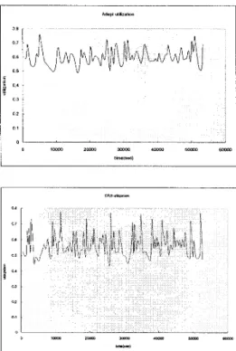
Figure 6 : The utilization of the robots
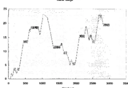
ters that we will examine are the robot utilization, the histogram of the finished product, and buffer utiliza- tion. In this simulation, we give Adept a high priority than CRS.
6.1 Simulation result
We assume the robot operation time ranges from 2
to 12 seconds in this simulation, and the time depends on the complexity of that operation. The average op- eration time is less than 10 seconds.
In the two robot simulation environment, the uti- lization of the robot is between 0.5 and 0.8 or so as shown in Fig 6. There are resource contention be-
tween the two robots. For example, the robots com- pete for the common workspace, for the shared buffer, and for the shared Eye-In-Hand camera PC. Instead, if only one robot is in operation, the utilization of the robot will be above 0.8. The scheduling time is thus 1 to 2 seconds for each robot operation.
7 Conclusion
This paper is an extension of [17]. The relationship between the agents and communication backbone EM- FAK is discussed in section 2. To meet the real-time
B v n n “saga
Figure 7: The buffer utilization
requirement in the robotic assembly environment, we use a decentralized approach t o solve the schecluling problem. The basic idea is using the concept of agent which is an autonomous entity that can communicate with each other to achieve a coorinated behaviour. Section 3 introduces the agent architecture anld the
functionality of the agent’s module. Section 3 also in- troduces the distributed resource allocation protocol that is used t o allocate the resources among a group of distributed agents. The benefits of using rnulti- agent based modelling exhibits flexibility, robusitness, and modularity. Section 4 describes the implementa- tion of the agents for the flexible assembly cell. The experimental result is given in section 5.
References
M. P. Groover, Automation, Production Systems, and Computer Integrated Manufacturing. Prentice-Hall Inter- national, 1987.
H. Kopetz, Scheduling, ch. 18, pp. 491-509. Addison- Wesley publishing company, 1993.
S. Karus, J . Wilkenfeld, and G. Zlotkin, “Multiagent ne- gotiation under time constraints,” Artificial Intelligence, vol. 75, pp. 297-345, 1995.
N.R.Jennings, “Controlling cooperative problem solving in industrial multi-agent systems using joint intentions,,’’ Ar- tificial Intelligence, vol. 75, pp. 195-240, 1995.
T. K.Tsukada and K. G.Shin, “Priam: Polite rescheduler for intelligent automated manufacturing,” IEEE “bansac- tion on Robotics and Automation, vol. 12, no. 2, pp. 235-
245, 1996.
E. Oliveria, “Cooperative multi-agent system for an as- sembly robotics cell,” Robotics and Computer-Intergrated Manufacturing, vol. 11, no. 4, pp. 311-317, 1994. R. J. Rabello and L.M.Camarinha-Matos, “Negotiation in multi-agent based dynamic scheduling,” Robotm and Computer-Intergrated Manufacturing, vol. 11, ino. 4,
pp. 303-309, 1994.
G . Cohen, “Concurrent system to resolve real-time con- flicts in multi-robot systems,” Robotics and Computer- Intergmted Manufacikring, vol. 8 , no. 2, pp. 169-175,
1995.
P. M. Pelagagge, G. Cardarelli, and M. Palumbo, “Some criteria to help the experimental setup of assembly cells with cooperating robots,” Robotics and Computer- Intergrated Manufacturing, vol. 12, no. 2, 1996.
Georgeff, “Communication and interaction in multi-agent planning,” Proceedings AAAI-83, pp. 125-129, 1983. F.-Y. Wang and G. N . Saridis, “A coordination theory for intelligent machines,” Automatica, pp. 833-844, 1990.
J. S. Barsran, E. M. Petriu, and D. C. Petriu, “Flexi- ble agent-based robot,ic assembly cell,’’ Proceedings IEEE
International Conference on Robotics and Automation, pp. 3461-3466, 1997.
A. A. Rizzi, J . Gowdy, and R. L. Hollis, “Agile assembly architecture: An agent based approach to modular preci- sion assembly systems,” Proceedings IEEE International Conference on Robotics and Automation, pp. 1511-1516,
1997.
H. ASAMA, K. OZAKI, Y. ISHIDA, K. YOKOTA, A. MATSUMOTO, H. KAETSU, and I. ENDO, “Collabo- rative team organization using communication in a decen- tralized robotic system,” Intelligent Robots and Systems, pp. 816-823, 1994.
R. G. SMITH, “The contract net protocol: High-level com- munication and control in a distributed problem solver,”
IEEE fiansactions o n computers, vol. C-29, no. 12, pp. 1104-1113, 1990.
V. K. Garg and B. Watldecker, “Detection of weak unstable predicates in distributed programs,” IEEE Zhnscations On Parallel And Dist!ributed Systems, pp. 299-307, 1994. T.-S. Huang, L.-C. Fu, and Y.-Y. Chen, “Design and anal- ysis of a dynamic scheduler for a flexbile assembly system,” Proceedings IEEE International Conference on Robotics and Automation, pp. 3334-3339, 1997.
C.-S. Jann and L.C.Fu, “Flexible control system for robot assembly automation I)) Proceedings IEEE International Symposium on Assenkbly and Task Planning, pp. 286-292,
1995.
H.-S. Huang, L.-C. F’u, and J. Y. jen Hsu, “Rapid setup of system control in a flexible automated production sys- tems,” Proceedings IEEE International Conference on Robotics and Automation, pp. 1517-1522, 1997.
D. E. Comer, Internetworking With TCP/IP Vol 1: Prin- ciples, Protocols, and Architecture. Prentice-Hall, 1991. W. R. Stevens, CJNIX network programming. Prentice-Hall International, 1991.
H. F. Wedde, B. Korel, S. Chen, D. C. Daniels, S. Na- garaj, and B. Santhanam, Ransparent Access to Lame Files That Are Stored accross Sites, ch. 9 , pp. 490-510. IEEE Computer society press, 1994.