A New Adaptive PMU Based Protection
Scheme for Transposed/Untransposed
Parallel Transmission Lines
Ching-Shan Chen, Student Member, IEEE, Chih-Wen Liu, Member, IEEE, and Joe-Air Jiang, Member, IEEE
Abstract—This paper proposes a brand-new adaptive phasor measurement unit (PMU) based protection scheme for both trans-posed and untranstrans-posed parallel transmission lines. The develop-ment of the scheme is based on the distributed line model and the synchronized phasor measurements at both ends of lines. By means of eigenvalue/eigenvector theory to decouple the mutual coupling effects between parallel lines, the fault detection and location in-dices are derived. The two proposed inin-dices are used in coordi-nation such that the internal and external fault events can be dis-tinguished completely. By on-line estimating the line parameters under the actual power system conditions, the proposed scheme will respond more accurately to power system faults. Extensive simulation results using EMTP have verified that the accuracy of the fault location achieved is up to 99.9%. The proposed protec-tion system responds well and fast with regard to dependability and security. All the results show that the performance of the pro-posed detection/location indices is independent of fault types, lo-cations, resistance, source impedance, fault inception angles, and load flows.
Index Terms—Computer relaying, digital protection, fault detec-tion/location, parallel transmission lines, phasor measurement unit (PMU).
I. INTRODUCTION
I
N ORDER to enhance reliability and security for bulk power transmission and to share the same right of way, par-allel transmission lines are commonly utilized in modern high voltage transmission networks. The fault detection/location for parallel lines thus become a noticeable investigation subject in electrical power industry. Conventionally, distance protection is one of the commonly used techniques in the protection of transmission lines. However, in case of using distance relay to protect parallel transmission lines, a number of problems due to mutual coupling effect, ground fault resistance, prefault system conditions, shunt capacitance, etc., will cause performance degradation [1]–[6].Some methods have been proposed for improving the distance protection performance of parallel lines protection [3]–[6]. These techniques are very instructive and achieve some degree of improvement for the distance protection of parallel lines; however, most of them possess some errors inherently due to the assumptions during the development process of those
Manuscript received April 3, 2001; revised September 17, 2001.
C.-S. Chen and C.-W. Liu are with the Department of Electrical Engineering, National Taiwan University, Taipei, Taiwan, R.O.C.
J.-A. Jiang is with the Department of Bio-Industrial Mechatronics Engi-neering, National Taiwan University, Taipei, Taiwan, R.O.C.
Publisher Item Identifier S 0885-8977(02)02725-5.
algorithms. For example, Jongepier et al. [4] used artificial neural networks to estimate the actual power system conditions and to calculate the appropriate tripping impedance. Hence, the distance protection inaccuracy caused by the continuously changing power system state is compensated. However, fault resistance is not taken into account in [4], thus, the accuracy of fault location may be influenced. In order to increase the accu-racy of fault distance estimation for distance protection, a new method that is independent of fault resistance, remote infeed and source impedance is proposed by Liao et al. [6]. Never-theless, the shunt capacitance is neglected, which introduces errors for long lines. Moreover, all studies mentioned above do not consider the influence of line parameter uncertainty, system frequency fluctuation and system noise on the accuracy of the proposed schemes. These factors can be solved in this paper.
Except the mentioned distance protection scheme, the direc-tional-transverse differential protection relays [1], [2] have been proposed recently. These techniques compare the average cur-rent or curcur-rent incremental signals of corresponding phases in the two parallel lines at the same end. The developed relays are quiet simple but they cannot provide fault location information and only can be used to protect two similar lines.
To ensure system stability, modern power systems require high speed protective relaying. An increase in power transfer of parallel lines thus calls for faster protection. With regard to this, traveling-wave-based or differential equation-based pro-tection [7]–[10] may be a way to decrease the fault clearing time and thus increase reliability. However, traveling-wave al-gorithms are very difficult to decide from the first arriving waves whether they were caused by a fault in the zone to be protected or by another disturbance [7].
Computer-based measurement, protection, and control sys-tems have become common features of electric power substa-tions [9]–[12]. IEEE has also made the standard synchrophasors for power systems [13]. Aiming such a trend, some synchro-nization measurement techniques have been proposed for trans-mission line protection systems [14]–[17]. These techniques use synchronized data from the two terminals and the performance and accuracy of protection systems have been improved over those limited to using only local data. Based on our previous work [16], [17], the authors have successfully developed a new adaptive phasor measurement unit (PMU)-based technique for parallel transmission lines. This technique eliminates many of the associated problems typically encountered in this area.
In this paper, the fault detection/location indices are derived. A brief outline of protection configuration and algorithm are 0885–8977/02$17.00 © 2002 IEEE
described. An adaptive line parameter estimation algorithm for transposed and untransposed parallel lines is proposed. Exten-sive EMTP simulation results used to illustrate the performance are given. Finally, the main features and contributions are pre-sented.
II. PRINCIPLE OF THEPROPOSEDFAULTDETECTION/ LOCATIONSCHEME
A. Review of New Fault Detection/Location Indices for Balanced Single-Circuit Lines
The authors have proposed a new adaptive PMU based fault detection/location technique that is suitable for any balanced three-phase single-circuit transmission line [16], [17]. In the previous work, we utilized a suitable transformation, referred to as the modal (or called Clarke) transformation [18], to de-couple phase quantities. The voltages at fault point (locates at km away from a receiving end, is the per unit length, and is the total length of the protected transmission line) and are taken as boundary conditions, the fault lo-cation index is therefore solved as
(1) where , , , and are the entries of 3 1 vec-tors , and , respectively, and are utilized to represent the 0, , and -modal components of signals. represents diagonal entries of the 3 3 modal propagation con-stant matrix. In terms of measured data at both ends of line, those signals quantities utilized in (1) can be expressed as the following: (2.1) (2.2) (2.3) (2.4) and (3) where represents diagonal entries of the 3 3 modal surge impedance matrix, and , , , represent received end/sending end voltage and current synchronized 0,
, modal measurements, respectively.
1) Fault Detection: Substituting the measured data
and into the formula of shows
that the phasors and are equal. This fact guarantees that the absolute value of for every moving data window is held at zero before the occurrence of a fault. However, as soon as the postfault measured data are input into the algorithm through the moving data window, the computed values of abruptly deviate from zero. Similar, index possesses the same characteristic as index . Hence, the and can serve as fault detectors.
2) Fault Location: When the moving window contains the
postfault sampled data, the and keep an approximate constant gap between each other and both rise abruptly. The phase angle between and is also almost a constant value after the occurrence of a fault such that the term
will be an approximate constant complex number. Since the other parameters in (1) are constant, the fault location index can quickly converge to a constant value between the 0 and 1 after the occurrence of a fault in protected zone. Thus, the index can serve as a fault locator. On the other hand, the term is a random complex number when external fault occurs. Even though the value of index may fall into the in-terval of [0,1], it cannot converge to a constant value. By setting a deviation threshold and a counter limit of index to check whether it converges to a stable value, the proposed algorithm can distinguish internal faults from external faults.
B. Perfectly Transposed Parallel Transmission Lines
The above basic fault location algorithm can be extended to transposed parallel transmission lines. As it is the same treat-ment of a single-circuit line, transposed parallel lines could also be decomposed into a number of uncoupled single-phase modes. This can be done by the following matrix transformation [18]
(4)
After some algebraic manipulations, six modal fault location indices can be easily derived with the same form as shown in (1).
C. Untransposed Parallel Transmission Lines
We have only considered the ideal transposed lines so far, however, the transmission lines usually are untransposed due to effects of parameters aging, asymmetry of the lines, etc. If the parallel lines are not transposed, then the transformation matrix of (4) can no longer be used; instead, depends on the partic-ular tower configuration. For an untransposed parallel transmis-sion line, the voltage and current phasors at any point along the line must satisfy the following equations:
(5.1) (5.2) Fortunately, the matrices of untransposed lines can be decou-pled as well, with transformations to modal parameters derived from eigenvalue/eigenvector theory. The modal transformation matrices for untransposed lines are no longer known a priori and must be calculated for each particular pair of parameter ma-trices and [18]. Using synchronized phasor measurement techniques, we can estimate on-line the line pa-rameters with very high accuracy, and therefore can find out a suitable transformation matrix by the eigenvalue/eigenvector theory to solve the aforementioned problem.
It becomes possible to transform the coupled (5.1) and (5.2) from phase quantities to modal quantities in such a way that the equations become two decoupled second-order differential equations which are as the following:
(6) (7) The detailed formulation is referred to [18]. From (6) and (7), six modal fault location indices can also be derived with the same form as (1). It is worthy of noting that the line capacitance is included, so the proposed algorithm is very suitable for long lines.
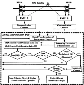
III. OVERALLCONFIGURATION
A. Data Synchronization
A PMU-based fault detection/location technique for three-phase single circuit transmission line and the practical imple-mentation of PMU has been presented in [16] and [17]. More-over, the synchronized performance of PMU has been demon-strated very well in the 161 kV substations of Taipower system [17].
B. Extraction of Fundamental Phasors
In order to attain a high degree of performance of fault detec-tion/location, it is vitally important to be able to accurately ex-tract the fundamental voltage and current phasors. The method used here is based on the new Discrete Fourier Transform based filtering technique (termed as SDFT) developed by our lab. An extensive series of studies have shown that the SDFT technique is very effective in rejecting frequency fluctuation, harmonics, and system noise [16], [17].
C. Communication Channel
Real-time quantities measured by the PMUs can be trans-mitted to the Central Discrimination Unit via a high-speed com-munication channel. The format of the transmitted synchronized data has been discussed in [13]. There are several communi-cation media such as microwave network, power line carrier, fiber optics, etc., that can be used to transmit PMU’s data. For example, the fiber optic communication networks permits to transmit large volumes of data (orders of Mb/s) from point to point with high reliability and lower error rate [9], [11]. If there is a suitable protocol, the impacts of communication channel on the dependability and security of the protection scheme can be further minimized. The total transmitted phasor data of our protection scheme (measured by one PMU at one bus of the pro-tected parallel line) whose data frame [13] can be conservatively encoded by 48 bytes (1 byte 8 bits) for every transmission. Considering a 100 kb/s channel, it takes 48 bytes/100 kb/s 3.84 ms (the propagation delay of communication channel is neglected since in general such a value is constant) to transmit every data frame. Suppose that a dedicated optic fiber channel is available, the delay will be reduced significantly. Therefore,
Fig. 1. Configuration of the proposed adaptive protection system.
high-speed for data transfer can be achieved such that the trans-mission delay will add only a few milliseconds to the tripping decision time of the proposed protection scheme.
D. Adaptive Protection Scheme
Refer to the configuration shown in Fig. 1, the proposed scheme is briefly described as the following.
1) PMUs serve as the data acquisition units. The new de-signed Global Synchronism Clock Generators (GSCGs, and the SDFT filtering algorithm [16], [17] have been built in PMUs such that the synchrophasors with high ac-curacy can be extracted from the real-time measured data. These synchronized phasors are then transmitted into the central discrimination unit via two communication chan-nels.
2) At the decoupling transformation stage, the phasor quantities are decoupled into modal components. In this study, the modal transformation matrix in (4) and eigenvalue/eigenvector theory to decouple the mutual coupling effect of transposed and untransposed lines, respectively, are used.
3) Using (1)–(3), the fault detection and location indices and are computed.
4) The line parameter estimation provides the on-line update of the line parameters at intervals of predetermined time. Hence, variation of line parameters will not affect the per-formance of the protection system.
5) The discrimination index and the location index are operated in a coordination manner to distinguish the internal faults from external faults. Such a deliberate pro-cedure is based on the statistical threshold values of and a counter limit.
6) By comparing the usable modal quantities, the faulted cir-cuit is identified when the fault occurs on protected lines. 7) Finally, the designed protection system performs a tripping decision strategy and displays the fault location.
The tripping decision strategy can guarantee that the proposed protection scheme will not issue an incorrect tripping signal.
E. Mode Selection and Faulted Circuit Identification
Under the case of transposed parallel lines, if the modal trans-formation matrix in (4) is used to decouple the phase compo-nents of measured signals into the modal quantities, then it will provide the modal pattern as shown in Table I. The “*” mark in the modal indices , , indicates that the accurate fault detection/location results can be obtained. From Table I, it is clearly seen that the usable modal indices in mode 3 6 with respect to circuit 1 and circuit 2 have different patterns. So, the identification task for transposed lines can be easily achieved. For example, if a fault occurs on circuit 1 of a parallel line, then the values of and are not between in-tervals of (0,1). Conversely, if a fault occurs on circuit 2, then the values of and are not between intervals of (0,1). By monitoring the values of the faulted circuit can be identified. For untransposed cases, however, it will provide six usable modes when we use the decoupling matrix computed from and . Therefore, by using the decoupling matrix for untransposed lines, the identification task cannot be achieved. We have to use another transformation matrix. For-tunately, the usable modal quantities are dominated by modal transformation matrix, so we can still use the transformation matrix of (4) incorporated with index to perform the identifi-cation task for untransposed lines. At this time, the usable modal quantities are the same as Table I. So, the faulted circuit of un-transposed parallel lines is identified. It is worthy to note that the accurate fault detection/location indices still have to be cal-culated by eigenvalue/eigenvector theory for untransposed lines. The faulted circuit identification by using (4) for untransposed lines is just an auxiliary part of the protection scheme.
IV. LINEPARAMETERESTIMATION
Almost all of the existing fault protection techniques did not consider uncertainty of the line parameters. It can be seen from [17], [19], and [20] that the error in line parameters can result in significant errors in fault location estimation for a transposed line. For an untransposed line, this error will further degrade the accuracy of fault location and especially deserves investigation.
A. Line Parameter Estimation for Transposed Lines
Using the PMU technique proposed by [16] and [17], we can on-line monitor the status of the transmission line, and extract
the phasor and from both ends of lines by
the SDFT filtering approach. These synchrophasors can be uti-lized to inversely derive the characteristic impedance and propagation constant of three-phase transmission line. The performance has been demonstrated by EMTP in detail [17].
B. Line Parameter Estimation for Untransposed Lines
For untransposed parallel transmission lines, the voltage and current phasors at any point along the line must satisfy
(8.1)
TABLE I
LIST OFCORRECTNESS OFFAULTLOCATIONINDEXDFORDIFFERENTFAULT TYPESUNDERMODALTRANSFORMATION
(8.2)
where and are 6 6 matrices.
Combining (8.1) and (8.2) gives
(9)
(10) We use Laplace Transform method to solve (9) and (10). From (9), we obtain that
(11) where denotes the 6 6 identity matrix. and are voltage and current phasors at the receiving end, respectively.
Equation (11) is further rewritten as
(12) Equation (12) can be reduced as
(13) where
and
are both 6 6 matrices.
The inverse of matrix can be expressed as
where
(15) Taking the Laplace inverse transform with respect to (13), then
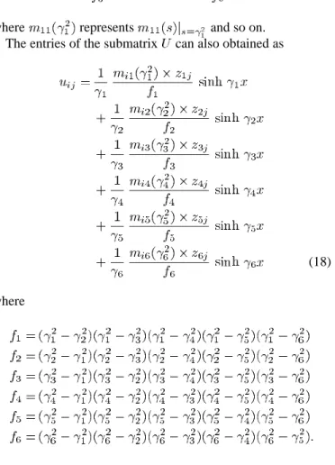
(16) where the entries of submatrix are expressed as follows:
(17)
where represents and so on.
The entries of the submatrix can also obtained as
(18)
where
So far, (9) is solved completely. The same treatment can be applied to the differential equation (10). Then
(19)
Hence, the voltages and currents at the sending end in terms of receiving end quantities are obtained as
(20)
Fig. 2. A single-line diagram of the simulated power system.
where all entries in the four submatrices , and are nonlinear expressions of the line parameters.
Due to nonlinearity of the mentioned matrices, the line pa-rameters must be calculated by a numerical iteration method. In this case, there are 72 variables that are unknowns in the four submatrices. These unknowns are the entries and in the parameter matrices and . Among these ables, it is convenient to further classify into three kinds of vari-ables, i.e., series resistance , series reactance and shunt admittance , where series impedance . Since and are symmetric matrices, only the 63 upper triangular entries should be determined. Since there are only 12 equations in (20), it is insufficient to solve the unknowns. To cope with this difficulty, we first decompose (20) into real and imaginary parts to form 24 equations. Moreover, it can be ex-pected that the line parameters would not vary during a short period. Based on this fact, we can respectively substitute three sample sets of voltage and current phasors measured by PMU’s at both ends of lines at different time into the 24 equations. Now, there are 72 equations and 63 unknown variables, so the least square method can be used to solve these nonlinear equations for line parameters.
V. SIMULATIONRESULTS
This paper is concerned with the application of the new pro-tection technique to a typical 345 kV parallel transmission lines with vertical configuration encountered in Taiwan. The perfor-mance of the protection algorithm is evaluated using data gen-erated by EMTP [21].
A. System Modeling
Fig. 2 is the sample system that consists of four transmission lines, four busbars, and two equivalent sources.
1) Thevenin Equivalent: An ideal three-phase sinusoidal source and a lumped three-phase coupled – branch are used. The phase angle between and is 20 . 2) Line Models: The transmission line model used in the
simulation is the distributed parameter model. The lines T3 and T4 are three-phase transposed lines. T3 and T4 are intentionally constructed to examine external faults. T1 and T2 are the protected parallel lines. Initially, the parameters of parallel lines are obtained by using EMTP program LINE CONSTANTS [22] based on Taipower Company tower geometry data.
B. Sampling Rate and Counter Limit
The data is sampled at sampling rate of 3.84 kHz (64 times 60 Hz), and the fault inception time is set at 37.47 (ms).
Fig. 3. Performance of fault detection/location indices with respect to internal faults in T1.
In this paper, we follow the manner proposed by Akke and Thorp [8] to choose the counter limit. The counter limit ( ) is calculated as
(21) where is the sampling interval. The parameter is a user-de-termined parameter that can be interpreted as the shortest time delay for a fault at the beginning of the line. In this study, we have used millisecond for all possible fault events. The data are sampled at a sampling rate of 3.84 kHz. Thus, a sam-pling interval of milliseconds gives a counter limit
of for all possible faults.
C. Performance Evaluation of Sensitivity of Fault Detection/Location Indices to Internal Faults
A number of EMTP simulations of various fault events were performed for testing these indices. Fig. 3 shows that the perfor-mance of detection/location indices is very sensitive to internal faults and is independent of fault resistance, fault types, fault lo-cations, and line configurations.
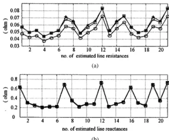
D. Performance Evaluation of Line Parameter Estimation
When the transmission lines are transposed, the accuracy of parameter estimation can be achieved up to 99.9% [17]. In this paper, only the line parameter estimation for untransposed lines is given. In order to simulate the effect of temperature on line parameter uncertainties, let the dc resistance of phase conduc-tors and ground wires be increased 120% with respect to orig-inal values. Moreover, we also change the skin effect correction factor [22] from 0.231 to 0.5 and earth resistance from 100 to 250 . The results calculated by [22] and the proposed algo-rithm are put together in Fig. 4 for comparison, where Fig. 4(a) and (b) show the 21 undetermined resistances and reactances,
(a)
(b)
Fig. 4. Results of parameter estimation for untransposed parallel lines.
Fig. 5. Statistical evaluation of the fault location estimation with respect to different faults occurring in T1 for transposed lines.
Fig. 6. Statistical evaluation of the fault location estimation with respect to different faults occurring in T1 for untransposed lines.
respectively. The reactances are mainly sensitive to tower con-figuration, so they have no obvious variation. In this paper, it is shown that the proposed algorithm provides good capability for tracking line parameters variations.
E. Performance Evaluation of the Accuracy of Fault Location Estimation
The criterion used for evaluation of the performance was an error of fault location defined as
error % actual location (p.u.)
–calculated location (p.u.) (22) At this stage, 445 different faults have been generated using EMTP for statistical evaluation of the fault location function. The simulated fault cases include different fault conditions. Figs. 5 and 6 gather the average location errors of the third cycle after the fault inception for transposed and untransposed tested cases, respectively. Generally, the average error does not exceed 0.311% and 0.0493% for transposed lines and untransposed lines, respectively.
TABLE II
TRIPPINGDECISIONTIME FORDIFFERENTFAULTTYPES ANDFAULTLOCATIONS
TABLE III
TRIPPINGDECISIONTIME FORDIFFERENTFAULTRESISTANCE
F. Performance Evaluation of Internal Faults Tripping Decision Time
Relaying performance of the proposed protection system was examined with respect to various faults. In this paper, the trip-ping decision time includes the time of fault detection and the identification of faulted line. Extensive different fault studies have verified that the tripping decision time for most cases is well within 1/2 cycle. The performance for transposed line cases are very well and are insensitive to various fault events. Due to the limited space, we will only present the examined results of untransposed line cases. The typical simulation results on the tripping performance of internal fault on line T1 are discussed in the following.
1) Effects of Fault Types and Fault Locations: Different
faults away from bus B (receiving end) were simulated. The results are given in Table II. It is clearly seen that the fault tripping decision time of the protection scheme is almost well within 1/2 cycle ( 8.3 ms) after the occurrence of faults.
2) Effects of Fault Resistance: Dependability of the distance
relaying decreases seriously under high resistance faults. The tripping decision times for different types and fault resistance under fault location 0.2 p.u. are listed in Table III. It is evidently seen from Table III the that the scheme is generally not affected by the magnitude of fault resistance.
3) Effects of Fault Inception Angles: Table IV shows the
typical performance of the protection scheme under different fault inception angles. These three fault events occur at point on a-phase voltage waves for every 45 spacing from 0 to 270 , re-spectively. The fault resistance is 10 . The fault location is set at 0.4 p.u. The results show that the proposed scheme maintains a high degree of stability and is almost independent of the fault inception angles.
TABLE IV
TRIPPINGDECISIONTIME FORDIFFERENTFAULTINCEPTIONANGLES
G. Effects of CT Saturation and CVT Transients
In order to investigate the effects of instrument transformers, the EMTP/ATP version models of CT and CVT are included in the simulation tests. A saturable transformer is adopted in the CT model [21]. The adopted CVT model consists of cou-pling capacitors, compensating reactor, step-down transformer, ferroresonance-suppression circuit, and resistive burden [23].
1) Simulation Results of CT Saturation: A three-phase
ground fault at 0.5 p.u. of the line T1 for transposed parallel lines with different CT burdens was simulated to test the pro-tection scheme. The faulted-phase saturated current waveforms are given in Fig. 7. Fig. 8(a) and (b) show the response curves of the fault detection and location indices, respectively. Although CT saturation severely distorts the current waveforms, the fault location index still converges quickly to the interval of (0,1). The shown test result reveals that the CT saturation does not severely affect the response of the proposed protection scheme.
2) Simulation Results of CVT Transients: To investigate the
effects of CVT transients, Fig. 9 shows a selected example with a-phase ground fault occurring at a voltage zero. The fault posi-tion is set at 0.95 (p.u.). For comparison, the ideal CVT voltage output (ratio voltage) is also shown in Fig. 9. Fig. 10(a) and (b) show the response curves of the fault detection and location in-dices, respectively. As shown in Fig. 10(b), the fault location index is affected slightly by CVT transients. The fault location index falls into the tripping interval of (0,1) quickly and satisfies the condition of the well-designed counter limit. So, the protec-tion scheme issues a tripping signal at 2.34 (ms) after fault in-ception. The test results show no significant effects from CVT transients on the proposed protection scheme.
H. Current Reversals
Assume a-phase ground fault occurring in line T2 for untrans-posed parallel lines. The fault position is set at 0.1 (p.u.) and the fault inception time is 37.47 (ms). After five cycles, the three phase circuit breakers of BUS B of line T2 are opened. At this moment, the currents on line T1 reverse its direction. Fig. 11(a) shows the response curves of the fault detection index. From Fig. 11, the proposed protection scheme can still detect a fault after clearing external fault occurred in line T2. Fig. 11(b) il-lustrates the curves of fault location indices based on the Clarke transformation (4) to distinguish faults between T1 and T2. As shown in Fig. 11, the mode 3 and mode 4 of the fault location indices will not converge to the tripping interval of (0,1) so the protection scheme will not issue a tripping signal for line T1. The proposed protection scheme remains secure for clearing ex-ternal faults on the parallel line that result in fault current rever-sals on the protected line.
Fig. 7. Three-phase current waveforms of sending end of the line T1.
(a) (b)
Fig. 8. Response curves of the (a) fault detection and (b) location indices with respect to CT saturation.
Fig. 9. A-phase voltage waveform of BUS A with respect to CVT transients.
(a) (b)
Fig. 10. Response curves of the (a) fault detection and (b) location indices with respect to CVT transients.
I. Evolving Faults
To test evolving faults, we simulate two successive faults oc-curred in the protected untransposed parallel lines. The first fault (a-phase ground fault) occurs in T1, which is located at 0.3 p.u. away from BUS B. The fault inception time is 37.47 (ms). Ten milliseconds later the second fault (a-b phase short fault) occurs in T2 at the same geometrical location. Fig. 12 shows the response curves of the fault location indices based on the Clarke transformation. As seen in Fig. 12, the proposed pro-tection scheme will first detect a fault occurred in T1 (mode 4 curve) and then a fault occurred in T2 (mode 5 curve). There-fore, both lines will be tripped successfully.
(a) (b)
Fig. 11. Response curves of the (a) fault detection and (b) location indices with respect to current reversals.
Fig. 12. Response curves of the fault location indices with respect to evolving faults.
Fig. 13. Response curves of protective indicesjMj and jDj when an external fault has occurred.
J. Performance Evaluation of External Faults and Intermittent Disturbance Discrimination
To test the performance of the protection scheme for faults oc-curring in outside of the protected line, 120 different fault cases are performed in line T3 and T4. Fig. 13(a) and (b) show the typical response of protective indices and . These fig-ures indicate that the index varies violently and index may fall into the tripping setting interval (0,1). This problem can be resolved by the well-designed counter limit. Therefore, the external faults would not cause any tripping of the proposed protection scheme. It has been demonstrated that the protec-tion scheme can correctly discriminate any fault occurring in the considered system. With regard to intermittent disturbance such as switching of power compensated capacitor, the response behavior of the fault detection/location indices are similar to external fault condition. So, intermittent disturbance would not cause the protection scheme tripping.
VI. DISCUSSIONS
The main features and contributions of the proposed protec-tion scheme are described in the following.
1) The performance of the detection/location indices is very good regardless of the transposed or untransposed line configuration. These two indices’ performance has been verified by extensive EMTP simulation tests.
2) In this paper, the on-line parameter estimation algorithm is derived. The line parameter uncertainty may affect the performance of the protection system. Generally, other papers ignore this important factor that is frequently en-countered in practical operation situations. Hence, the new protection algorithm can overcome the degradation of line parameters uncertainty on the traditional fault lo-cators.
3) The proposed protection algorithm adopts distributed line model. Based on this fact, the accuracy of fault location calculated by the new method is better than traditional fault locators. Moreover, the proposed scheme can pro-tect full line length and is not affected by power system conditions. Such capabilities can cope with the problem that the zone-to-be-protected of total line length of dis-tance relay is highly influenced by power system states [3].
4) The proposed protection algorithm can also detect and locate high impedance faults. In general, the variation of currents is slight when the high impedance fault occurs. This will affect the performance of differential-cur-rent-based or impedance-based protection algorithm. Moreover, differential-current-based algorithm cannot provide fault location information. However, the pro-posed scheme is almost independent of fault ground resistance.
5) Even multiple faults occur on both circuits for parallel lines simultaneously, the proposed protection scheme can detect faults quickly. The protection scheme provides the same excellent fault detection ability for transposed/un-transposed parallel lines under multiple faults. In general, the tripping decision time of the scheme for untransposed cases is slightly longer than that of transposed ones since the protection scheme needs a few sample steps to do the job of faulted-circuit identification for untransposed lines. Whether the protected line is of the transposed or untrans-posed type, the prountrans-posed scheme can provide the same good result.
6) There is a trade-off between dependability and security. Conservative selection of the trip threshold results in longer tripping decision time and higher security and vice versa. By using statistical analysis to select the thresholds of deviation of , the protection scheme shows good performance with respect to dependability and security. For instance, the setting values are
and for simulated transposed
parallel lines.
VII. CONCLUSION
A new adaptive PMU based protection scheme for parallel transmission lines has been presented. Specifically, a fault
de-tection index and a location index suitable for transposed and untransposed parallel lines are derived. These indices are the-oretically accurate and reliable. A new parameter estimation algorithm for untransposed parallel lines has also been devel-oped. Employing on-line parameter estimation, it is effectively to solve the performance degradation of fault detection/location caused by parameter uncertainty.
Thousands of EMTP fault studies prove the protection scheme to be very accurate and robust. The accuracy of the fault location can be up to 99.9%. Also, the results have shown that the protection scheme correctly discriminates between internal faults and external faults. Almost for all the tests, the time for identifying an internal fault is well below 1/2 cycle.
REFERENCES
[1] M. I. Gilany, O. P. Malik, and G. S. Hope, “A digital protection technique for parallel transmission lines using a single relay at each end,” IEEE
Trans. Power Delivery, vol. 7, pp. 118–125, Jan. 1992.
[2] M. M. Eissa and O. P. Malik, “A new digital directional transverse differ-ential current protection technique,” IEEE Trans. Power Delivery, vol. 11, pp. 1285–1291, July 1996.
[3] A. G. Jongepier and L. van der Sluis, “Adaptive distance protection of a double-circuit line,” IEEE Trans. Power Delivery, vol. 9, pp. 1289–1297, July 1994.
[4] , “Adaptive distance protection of double-circuit lines using artifi-cial neural networks,” IEEE Trans. Power Delivery, vol. 12, pp. 97–105, Jan. 1997.
[5] P. G. McLaren, I. Fernando, H. Liu, E. Dirks, and G. W. Swift, “En-hanced double circuit line protection,” IEEE Trans. Power Delivery, vol. 12, pp. 1100–1108, July 1997.
[6] Y. Liao and S. Elangovan, “Digital distance relaying algorithm for first-zone protection for parallel transmission lines,” Proc. Inst. Elect.
Eng.—Gen. Transmiss. Distribut., vol. 145, no. 5, pp. 531–536, Sept.
1998.
[7] M. H. J. Bollen, “Traveling-wave-based protection of double-circuit lines,” Proc. Inst. Elect. Eng. C, vol. 140, no. 1, pp. 37–47, Jan. 1993. [8] M. Akke and J. S. Thorp, “Some improvements in the three-phase
dif-ferential equation algorithm for fast transmission line protection,” IEEE
Trans. Power Delivery, vol. 13, pp. 66–72, Jan. 1998.
[9] A. G. Phadke and J. S. Thorp, Computer Relaying for Power
Sys-tems. New York: Wiley, 1988.
[10] A. T. Johns and S. K. Salman, Digital Protection for Power
Sys-tems. London, U.K.: Peter Peregrinus, 1995.
[11] Power Engineering Education Committee and the Power System Re-laying Committee of the IEEE Power Engineering Society, “Advance-ments in microprocessor based protection and communication,” IEEE
Tutorial Course, 1997.
[12] Working Group H-7 of the Relaying Channels Subcommittee of the IEEE Power System Relaying Committee, “Synchronized sampling and phasor measurements for relaying and control,” IEEE Trans. Power
De-livery, vol. 9, pp. 442–452, Jan. 1994.
[13] Working Group H-8 of Relay Communications Subcommittee of the IEEE Power System Relaying Committee, “IEEE standard for synchrophasors for power systems,” IEEE Trans. Power Delivery, vol. 13, pp. 73–77, Jan. 1998.
[14] M. Kezunovic´ and B. Peruniˇcic´, “Automated transmission line fault analysis using synchronized sampling at two ends,” IEEE Trans. Power
Syst., vol. 11, pp. 441–447, Feb. 1996.
[15] H. Y. Li, E. P. Southern, P. A. Crossley, S. Potts, S. D. A. Pickering, B. R. J. Caunce, and G. C. Weller, “A new type of differential feeder protec-tion relay using the global posiprotec-tioning system for data synchronizaprotec-tion,”
IEEE Trans. Power Delivery, vol. 12, pp. 1090–1097, July 1997.
[16] J. A. Jiang, J. Z. Yang, Y. H. Lin, C. W. Liu, and J. C. Ma, “An adap-tive PMU based fault detection/location technique for transmission lines, Part I: Theory and algorithms,” IEEE Trans. Power Delivery, vol. 15, pp. 486–493, Apr. 2000.
[17] J. A. Jiang, Y. H. Lin, J. Z. Yang, T. M. Too, and C. W. Liu, “An adap-tive PMU based fault detection/location technique for transmission lines, Part II: PMU implementation and performance evaluation,” IEEE Trans.
Power Delivery, vol. 15, pp. 1136–1146, Oct. 2000.
[18] H. W. Dommel, EMTP Theory Book, 2nd ed. Vancouver, BC, Canada: Microtran Power Syst. Anal. Corp., May 1992.
[19] A. T. Johns and S. Jamali, “Accurate fault location technique for power transmission lines,” Proc. Inst. Elect. Eng. C, vol. 137, no. 6, pp. 395–402, Nov. 1990.
[20] D. J. Lawrence, L. Z. Cabeza, and L. T. Hochberg, “Development of an advanced transmission line fault location system, Part II: Algorithm development and simulation,” IEEE Trans. Power Delivery, vol. 7, pp. 1972–1981, Oct. 1992.
[21] Alternative Transient Program Rule Book, vol. 1, X. U. Leuven Center, Leuven, Belgium, July 1987.
[22] Alternative Transient Program Rule Book, vol. 2, X. U. Leuven Center, Leuven, Belgium, July 1987.
[23] M. Kezunovic´, Y. Q. Xia, C. W. Fromen, and D. R. Sevcik, “Distance relay application testing using a digital simulator,” IEEE Trans. Power
Delivery, vol. 12, pp. 72–82, Jan. 1997.
Ching-Shan Chen (S’01) was born in Taichung, Taiwan, R.O.C., in 1975. He received the B.S. degree in electrical engineering from National Taiwan Univer-sity of Technology and Science, Taipei, Taiwan, and the M.S. degree in electrical engineering from National Taiwan University (NTU), Taipei, in 1998 and 2000, respectively. He is currently pursuing the Ph.D. degree in electrical engineering at NTU.
At present, his research interests include computer relaying and the applica-tion of artificial intelligence to power system protecapplica-tion.
Chih-Wen Liu (S’93–M’96) was born in Taiwan, R.O.C., in 1964. He received the B.S. degree in electrical engineering from National Taiwan University (NTU), Taipei, Taiwan, and the M.S. and Ph.D. degrees in electrical engineering from Cornell University, Ithaca, NY, in 1987, 1992, and 1994, respectively.
Since 1994, he has been with NTU, where he is Associate Professor of elec-trical engineering. His main research interests include application of computer technology to power system monitoring, operation, protection, and control. His other research interests include motor control and power electronics.
Dr. Liu serves as a reviewer for IEEE TRANSACTIONS ONPOWERSYSTEMS and IEEE TRANSACTIONS ONPOWERDELIVERY.
Joe-Air Jiang (M’01) was born in Tainei, Taiwan, R.O.C., in 1963. He received the B.S. degree from National Taipei University of Technology, Taipei, Taiwan, and the M.S. and Ph.D. degrees in electrical engineering from National Taiwan University (NTU), Taipei, in 1983, 1990, and 1999, respectively.
From 1990 to 2001, he was with Private Kuang-Wu Institute of Technology and Commerce, Taipei. Then he came to NTU where he is now Assistant Pro-fessor of bio-industrial mechatronics engineering. His area of interest is in com-puter relaying, mechatronics, and bio-effects of EM-wave.