J. Frmklin Ins/. Vol. 335B. No 6. pp 1053 1068, 1998 Pergamon PII: S0016-0032(97)00050-1 Pubhshed by Elsewer Scm~ce Ltd ‘6s 1998 The Frankbn lnstlfute Prmted I” Great Bmam OOiWO32:98 %19.00+000
An Integrated Method in Wawelet-based Image
Compression
by HUNG-HSENG HSU,* YI-QIANG HU Und BING-FE1 WU
Department
of
Control Engineering, National Chiao Tung University, Hsinchu,Taiw,an
(Received in$nalform 5 February 1997; revised 10 April 1997; accepted 1 May 19971
ABSTRACT : In this paper, we propose an integrated image compression method, which contains the discrete wavelet transform, scalar guantization and some lossless codings, to gain higher compression ratios while maintaining the image fidelity. The discrete wavelet transform has the properties of entropy reduction andenergy concentration in high jrequency subimages. An innovative approach, called revised run-length coding, is proposed to improve the compression performance.
The idea of this approach is to represent the appearance of symbols of the run-length code in exponential expression,for saving the storage in bits. The dtfjerentialpulse code modulation is used to reduce the entropy of the lowest frequency subimage of the discrete wavelet transform and to achieve high compression effects losslessl_v. 0 1998 The Franklin Institute. Published by Elsevier Science Ltd
1. Introduction
A major objective of image compression is to represent an image by as few bits as
possible while preserving the level of quality. Non-essential information is discarded
to reduce the storage and transmission time in communication; see page 589 of (1). We
usually compress an image as a prelude to either image storage or transport. This is
because both of these operations are sensitive to the amount of data in an image; see
page 179 of (2). Even though many compression techniques have been developed and
implemented successfully up to now, there are still many innovative algorithms to be
proposed based on the discrete wavelet transforms (DWT), which have been applied
to the domain of image processing during the past ten years (3).
The fundamental idea behind the DWT is to analyze the signal according to scales
and has the intention of a multiresolution technique; see page 399 of (4). From the
application point of view, the DWT is regarded as one kind of the pyramid subband
coding; see page 213 of (5). Also, the image can be split into different frequency
*To whom all correspondence should be addressed. E-mail: bwu(a;haeshiuh.cn.nctu.edu.tw, Tel.: +886-3-5712121, ext. 54313. Fax: +886-3-5712385.
1054 Hung-Hseng Hsu et al.
components by the DWT. Each component, with a resolution matched to its scale, is
considered as the DWT coefficient. The wavelet-based coding has been demonstrated
to outperform other waveform based codings (6). We also derived the property of
entropy reduction through the DWT (7). The effect of energy concentration in high
frequency subimages is also observed; see page 373 of (8). Moreover, the histograms
of the higher frequency subimages, which are called detailed images of the DWT, can
be modelled to be generalized Gaussian distributed (9). The application of scalar
quantization (SQ) extended the detailed images are motivated to obtain better com-
pression conditions. This inherency of the DWT makes it interesting and useful to
apply to image compression.
In this paper, we propose an integrated image compression method, which contains
the DWT, SQ and some lossless codings, to gain higher compression ratios (CR) while
maintaining the image fidelity. The (9,7) taps’ wavelet, which belongs to the family of
a spline variant with less dissimilar lengths, is chosen to be the basis of the DWT (9).
In SQ, we introduce an optimal SQ (10) to increase the peak signal-to-noise ratio
(PSNR), which is a performance index of the picture quality. Furthermore, some
lossless codings, Huffman coding (HC), run-length coding (RLC) and differential pulse
code modulation (DPCM) are provided to increase the CR without further distortion.
We also combine the HC and RLC, denoted as HC + RLC, to achieve more com-
pression effects than HC or RLC, separately. Meanwhile, an innovative approach,
called revised run-length coding (RRLC), is proposed to lift the CR massively. The idea
of RRLC is to represent the appearance of symbols of run-length codes in exponential
expressions of base 2 for saving the storage in bits. It is also one kind of variable-
length codings. The contribution of this paper is to provide an integrated compression
technique, including the DWT, SQ, DPCM and lossless codings, to achieve higher
compression performance and image fidelity. Comparisons of our approach with JPEG
and other well-known approaches are also presented (1 l-14).
The organization of this paper is as follows. The flow chart of an integrated image
compression procedure is portrayed in Section 2. The ideas of the integrated com-
pression system are also discussed. In Section 3, we address the function of SQ and
some coding methods individually. The innovative idea of RRLC, which expresses the
run-length codes exponentially, is mentioned for more details. In Section 4, two testbed
images, Lena and Mandrill, are considered to verify the increment of CR and PSNR
performed after the integrated compression method. A concise conclusion is made in
Section 5.
ZZ. Image Compression by the D WT
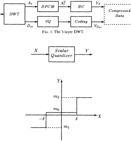
In this paper, we consider the 3-layer DWT of an image, as shown in Fig. 1. A,
represents to the lowest frequency subimage functioned after the DWT and D,,, where
x represents h, u or d, respectively, and i = 1,2,3, denotes the detailed images of each
layer of the DWT. For A3, the energy and the histogram are almost the same as those
of the original image, since the energy of the image to be compressed is always
concentrated in lower frequencies, in general. The coding method DPCM is suggested
to maintain the image loyalty and to reduce the entropy of AX. Hence, the HC is
An Integrated Method in Wavelet-based Image Compression 1055
~~~~~~:~~~~~~
FIG. 1. The 3-layer DWT.
FIG. 2. The integrated image compression system.
detailed images satisfy the generalized Gaussian distributions (9) we introduce the SQ
to compress the data with little distortion. There needs for some lossless coding methods
to obtain further compression effects. Our intention is to derive the integrated com-
pression system, as shown in Fig. 2. The component Coding in Fig. 2 represents one of
the methods, HC, RLC, RLC+HC or RRLC.
After the image is transformed by the DWT, the subimages A3 and D,i are obtained
directly. The information contained in A3 is important so that the lossless coding
methods behind A, are suggested to prevent any further distortion. Moreover, the
histogram of A3 and that of the original image are almost the same. It reveals that both
entropies are approximately equal (7). When the DPCM is adopted, the entropy of A,
can be reduced apparently. In addition, A:, the output of DPCM, has a largely reduced
variance compared with Ai; see page 61 of (15). Following that, the function of HC,
which is a lossless coding method, is adopted to obtain the data YA.
The histograms of D,i can be modelled as the generalized Gaussian distributions (9).
1056
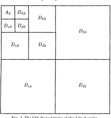
Hung-Hseng Hsu et al. A3 Dh3 Dh2D
v3 Dd3D
v2 Dd2Dhl
FIG. 3. The I/O characteristic of the 34evel scalar.
the quantizer, is introduced to gain better compression performance at the cost of
producing some quantization error. The global minimum of quantization error can be
obtained by using algorithms presented in our previous work
(10).
Furthermore, losslesscoding methods are provided to reach higher compression ratios without any loss of
quality. The output generated by these lossless coding is denoted by D.,i.
III. Quantization
and Lossless CodingsThe fundamental ideas of scalar quantization and lossless codings will be addressed
in the following discussions.
3.1. Optimul SQ
The previous section mentions that every detailed image Dri could be quantized by
the 3-level scalar quantizer with symmetrical decision levels, since these histograms of
the detailed images can be modelled as the generalized Gaussian distributions. SQ is
the only component to introduce error during the whole process of image compression.
The performance index PSNR is usually used in image coding and defined as follows:
PSNR = 1Olog,,+&,
where MSE is the abbreviation of mean squared error. The optimal value of PSNR
An Integrated Method in Wavelet-based Image Compression 1057
(10). The higher the values of PSNR, the better the fidelities of the reconstructed
images. Unfortunately, higher values of PSNR usually lead to worse values of CR.
Hence, we need to deviate the value of decision level from the optimal value to obtain
better CR.
3.2. Lossless codings
3.2.1. DPCM coding. In general, the information contained in the lowest frequency
component of the 3-layer DWT, A3, is rich enough such that we cannot conduct any
further distortion by the lossy compression technique. The histogram and entropy of
A3 are almost the same as those of the original picture. The lossless coding DPCM
could be introduced, since the histogram of the output of DPCM is highly concentrated
around zero and resembles the Laplacian distribution (see page 78 of (16)) of the form
P(x) = &w(-;‘illll4,
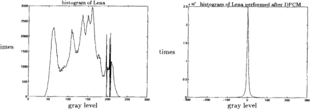
where G’ is the variance of the distribution. In general, the histograms of the output of
DPCM corresponding to different images have roughly the same shapes but different
variances (15). Obviously, the entropy and standard deviation are heavily reduced after
DPCM, as shown in Fig. 4. The entropy and standard deviation of Lena are 7.3039 bpp
(bits per pixel) and 44.0826, respectively. After DPCM, the entropy and standard
deviation are 4.9476 bpp and 10.9551, respectively. It implies that we have the oppor-
tunity to gain the lossless compression ratios of g/4.9476 = 1.6169 instead of
S/7.3039 = 1.0953. Hence, the DPCM is adopted by the lowest frequency component
to reach the better compression conditions without generating any more distortion.
Apparently, the HC will be adopted to perform the entropy reduction after DPCM.
3.2.2. RRLC. There are three kinds of output levels, m,, m, and m,, when a detailed
image is quantized by a 3-level scalar quantizer. For convenience, m,, m, and m, are
represented by 0, - 1 and 1, respectively. A value of the input signal which is less than
- 6 is mapped to the symbol - 1, a value which lies in the interval of [ - 6,6] is denoted
by the symbol 0 and a value which is larger than 6 is represented by the symbol 1.
Actually, the probability of appearance of the symbol 0 is higher than that of each of
histogram of Lena ‘A
o!d
gray level
Tome< after ?PCM /
1058 Hung-Hseng Hsu et al.
the other symbols since the histograms of the detailed images concentrate at the
neighborhood around zero.
The detailed images, which contain the higher frequency components, pick the edge
in the spatial domain of the original image. An edge in the image is a boundary or
contour at which a significant change occurs in some physical aspect of the image.
Hence, the detailed images performed after the DWT have the intent of edge detection
in image processing. That is, the values which are mapped to the symbol 1 or - 1
characterize that the change of the image intensities are positive or negative, respec-
tively, in the spatial domain of the original image. Moreover, the values which are
symbolized by 0 describe the smoothing parts of the original picture. For example, the
image of Lena seems to have many connected areas which deal with low spatial
frequencies. Hence, a lot of symbols 0 will be generated continuously in these detailed
images. The coding method RLC is helpful to process this situation.
In RLC process, both the symbol and the number of appearances of the symbol
should be stored as a code. For example, in the case of D,,, in Lena, the gray levels
after the 3-level scalar quantizer with decision level equal to 10.6 are as follows:
30105
h,...,,l,l,l,-l,-1,-1,-l,....
The run-length codes are shown in the sequence
(0;30105),(1;3),(- 1;4), .
In each pair of parentheses, the former is for the symbol and the latter is for the number
of appearances. Since the symbols and the appearance frequencies can be distinguished
from the location point of view, we encode the symbols 0, 1 and - 1 as 00, 01 and 11,
respectively. However, the appearance frequencies of symbols are unpredictable in real
cases. It is troublesome in bit allocations. By the above example, the number of
appearances should be assigned by 15 bits, which are the minimum bits to encode the
valueof30105. That is, the binary representation of 30105 is 111,010,110,011,001. It is
not economical to encode the values of 3 or 4 by 15 bits since they could be encoded
by 2 bits only, in practice. The total bits we need to represent the three run-length codes
are (2 + 15) x 3 = 5 1. This is the so-called fixed-length coding. The RRLC method is
proposed to solve this problem by representing the appearance frequencies expo-
nentially and is a kind of variable-length codings.
The idea of RRLC is to depict the appearance rate by exponential codes with base
2 for saving the bits we need. A group of revised run-length codes include data codes
(d-code, 2 bits/code), appearance codes (a-code, a bits/code), page codes (p-code, p
bits/code) and an identification code (id-code, 10). Hence, the revised run-length codes
are of the form
d-code a-code d&code a-code
An Integrated Method in Walelet-based Image Compression 1059 2”+ I a P P
? ?
o,m, 10 , Mm O...O,n a )...) a, -V-Md&code u-code id-code p-code v
for the value of appearance rate greater than 2*‘, where 0, A and 0 represent the
data bit, appearance bit and page bit, respectively. For example, we consider the case
with u = 3 and p = 2. Hence, the pair of (0;30105) can be encoded as
d-code a-code id-code p-code a-code *
G- (-. Gi -G, lo ,010, 110, 011, OCJI,
where these 15 bits, which are marked by the underlinings, represent the binary expan-
sion of 30105. Using this strategy, the run-length code of (0;30105) can be encoded by
2 1 bits. Moreover, the run-length codes of (1;3) and (- 1;4) are encoded as 0 1,011 and
11,100, respectively. The total bits we need to encode the three pairs of run-length
codes are 2 1 + 5 + 5 = 3 1 bits which is less than the 51 bits generated by the fixed-length
coding. If the changes of the number of appearances are large enough such that we
cannot code them by fixed numbers of bit allocation efficiently, the RRLC method is
better than the traditional RLC method.
IV. Experimental Results
Two examples of 2-D images, Lena and Mandrill, are provided to illustrate the
results which have been discussed before. The testbed images are of 512 x 512 pixels
with g-bit gray levels. The filters for the DWT are (9,7) taps’ filters which belong to the
family of a spline variant (9). The structure of the DWT follows Mallat’s algorithm
(3) which deals with the 2-D image problems and which is a kind of pyramid subband
codings. Here, A, represents the lowest frequency subimage of the first layer (resolution
l/2) DWT decomposition, and D,,,, D,., and DcI, are the horizontal, vertical and diagonal
oriented subimages with resolution l/2, respectively.
4.1. The choice cfS
The increment of PSNR brings about the decrement of CR. in general. That is a
trade-off problem. Suppose that we choose the optimal value of decision levels S*,
which is the value of 6 such that the MSE is minimum; then CR is usually very low.
To overcome the drawback of lower values of CR, the values of 6 should be altered
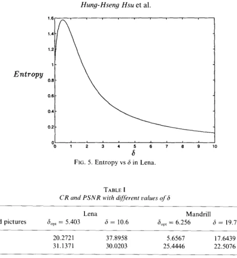
for increasing CR. In our previous work (17) the entropy of the output signal performed
after a 3-level scalar quantizer has a global maximum log, 3 if the input signals of the
quantizer, i.e. detailed images, are generalized Gaussian distributed. The entropy can
be considered as the lowest bound of bpp which has the similar meaning to CR. Hence,
we can reduce the entropies or raise CR by enlarging the values of 6. See Fig. 5 for
more details. For the case of Lena in Table 1, the value of 6 increases from 5.403 to
1060 Hung-Hseng Hsu et al. Entropy 0.6 - 0.4 - 0.2 - 0 1 2 3 4 a" 6
FIG. 5. Entropy vs 6 in Lena.
TABLEI
CR and PSNR with different vulues of 6
Lena Mandrill
Testbed pictures S”,, = 5.403 6 = 10.6 6,,, = 6.256 6 = 19.7
CR 20.2721 37.8958 5.6567 17.6439
PSNR 31.1371 30.0203 25.4446 22.5076
to maintain the PSNR over 22.5dB for the case of Mandrill, the value of 6 can be
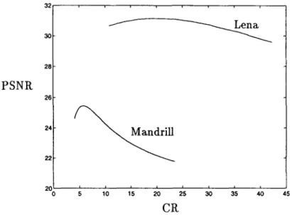
chosen as 19.7. The relationships of PSNR and CR in Lena and Mandrill with 6
increase from 3 to 12 and 24, respectively, are shown in Fig. 6. The original pictures
and reconstructed pictures with different PSNRs of Lena and Mandrill are shown in
Figs 7 and 8, respectively.
4.2. Improvement
qf
A, by DPCMIn order to reduce the entropy of A3 for further compression, the concept of DPCM,
which is a lossless compression, is introduced. Figure 9 shows that the energy of A,
has been concentrated after DPCM. Moreover, the entropy and standard deviation
reduction of these two testbed pictures are shown in Table 2. By the good characteristic
of DPCM, the HC is used to increase the CR of A3. Actually, the CR of the overall
compression system is raised from 33.7439 to 37.8958 in the case of Lena.
4.3. Compression bq’ HC, RLC, RLCf HC and RRLC
HC and RLC are the popular lossless codings in image compression, and can behave
An Integrated Method in Wavelet-based Image Compression 32 1061 30- 20 -
PSNR
26- 24: 22 \Mandrill
20 0 5 10 15 20CR25
30 35 40 45FIG. 6. Curves of PSNR vs CR in Lena and Mandrill.
(b)
FIG. 7. (a) Original Lena and the reconstructed pictures with PSNR = 30.0203.
(b)
(b) PSNR = 31.1371,
(cl
FIG. 8. (a) Original Mandrill and the reconstructed pictures with (b) PSNR = 25.4446, PSNR = 22.5076.
An Integrated Method in Wavelet-based Image Compression 1063 TABLE II
Improvement of A, of Lena and Mandrill in CR, Entropy and Standard deviation by DPCM and HC
A,$-DPCM-tHC Lena (6 = 10.6, RRLC) CR Entropy Standard deviation Mandrill (6 = 19.7, RRLC) CR Entropy Standard deviation 37.8958 33.7439 6.3334 7.2091 27.5101 40.9785 17.6439 17.0753 6.2357 7.0217 20.0737 33.0999
respectively. Since the DWT has the properties of entropy reduction (7) and subband
decomposition, the entropies and energy of the detailed images become small and the
appearance of symbols are continuous. Hence, HC and RLC are useful to encode the
output of the 3-level SQ performed after the DWT. For the case of Lena, the energy
of detailed images is smaller than that of Mandrill. It implies that RLC has a better
compaction in the case of Lena. Additionally, for each detailed image, the entropy
depends on the sum of the original entropy and the logarithm of the relative energy
(7). In the case of Mandrill, the entropies of the detailed images are larger than those
of Lena since the original entropy and relative energy of Mandrill are both greater than
those of Lena. It implies that HC can do better in the case of Lena than in the case of
Mandrill. In addition, as 6 increases, the increment of CR in RLC is better than that
of HC since the contiguous area in spatial domain is expanded. See Fig. 10 for more
details. Furthermore, the combination of RLC and HC, to obtain the benefit of
these two methods, is introduced to increase CR. The difference of the CR between
RLC + HC and RLC is by about 2 and 4 for the cases of Lena and Mandrill, respec-
tively. RRLC achieves the best CR for both Lena and Mandrill, as illustrated in Fig.
10. The simulation results by HC, RLC, HC + RLC and RRLC are listed in Table 3
with the same PSNR.
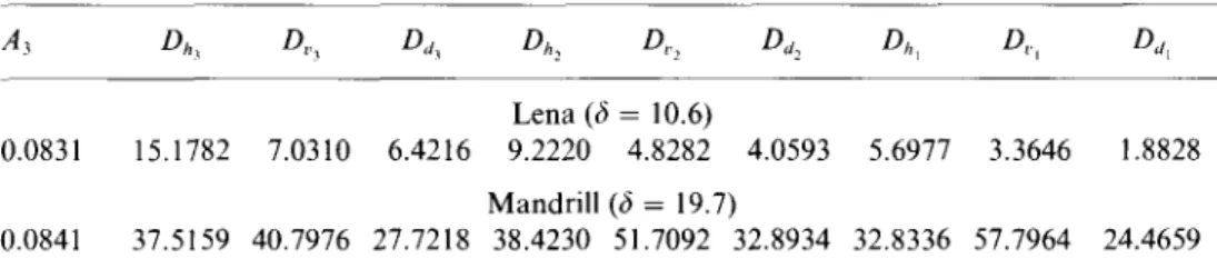
4.4. Increasing the decision levels of SQ
After the 3-level scalar quantizer, the MSEs of these subimages are not the same, in
general. The MSE of the lowest frequency component A3 is due to the rounding effect.
In the case of Lena, the differences of these errors, indicated in Table 4, are of the order
of tens of thousands. We notice that, for the DWT, the MSEs are preserved by the fact
that the energy conservation is sustained (7). That is, the sum of the mean squared
errors in the DWT subimages is identical to that of the reconstructed image. Hence,
we have the idea of increasing the number of decision levels for the subimages which
yield larger MSE. In other words, we consider the cases of 4 levels or more scalar
PSNR
Lena
RRLC
- RLC+HC RLC -. HC -- -PSNR
Mandrill
FIG. 10. PSNR vs CR by different coding methods (a) for Lena, 6 increases from 3 to 12, (b) for Mandrill, 6 increases from 3 to 24.An Integrated Method in Wavelet-based Image Compression 1065
TABLE III
CR by using different coding methods in Lena and Mandrill
Coding method HC RLC RLC+HC RRLC
Lena (6 = 10.6) 7.3061 26.7245 28.3713 37.8958
Mandrill (6 = 19.7) 7.0608 10.5625 13.6207 17.6439
TABLE IV
Rounding error of A, and MSE of detailed images after a 3-level scalar quantizer
Lena (6 = 10.6)
0.083 1 15.1782 7.0310 6.4216 9.2220 4.8282 4.0593 5.6977 3.3646 1.8828 Mandrill (6 = 19.7)
0.0841 37.5159 40.7976 27.7218 38.4230 51.7092 32.8934 32.8336 57.7964 24.4659
frequency to higher frequency components. Hence, we usually increase the numbers of
decision levels in lower frequency components, e.g. D3, to avoid losing PSNR too
much. On the other hand, we reduce the rounding levels of A3 since the rounding
error is always smaller than other MSEs generated by the detailed images. After this
improvement, the PSNR and CR are obviously lifted by about 1.5 and 2, respectively.
In the case of Mandrill, the improvement is not clear since the energy of the higher
frequency almost spreads out equally. That is, the energy of each component in detailed
images is approximately equal. The PSNR vs CR curves are shown in Fig. 11.
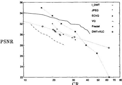
4.5. Comparisons with other methods
The performance of several well-known compression techniques are compared with
our method, as illustrated in Fig. 12. Our integrated compression method using the
DWT is abbreviated as LDWT. JPEG, which is the standard protocol of image
compression, is broadly used in real applications. The discrete cosine transform (DCT)
is adopted as the transformation technique. The quality of reconstructed images reduces
rapidly when CR increases (13). When CR is over the value of 21, our method performs
better than JPEG. The approach of vector quantization (VQ) is proposed by Gersho
and Ramamurthi (12) to diminish the distortion induced by SQ and is indicated for
comparison. Both PSNR and CR of VQ are not good. The revised method of VQ,
entropy constrained vector quantization (ECVQ) (11) is also considered for compari-
son. The quality of decompressed picture is always lower than that of ours. Besides,
the computation time and blocking effect are problems for implementation and the
PSNR of ECVQ will descend in high compression ratios. Moreover, there are many
PSNR
CR
PSNR
CR
FIG. 11. The improvements of PSNR and CR after adding several decision levels and reducing the rounding levels of A,.An Integrated Method in Wavelet-based Image Compression 1067 36 I_Dwl I JPEG . 34- ECVQ x .J2_. ” .; VQ -. \ Fmaal + \ OwT+VLC 0 30-
PSNR
‘.
??..:. .. . .
28 - . . ‘.I. ‘.... .., ‘.. .‘a r 26 - 24 22 10 20;R
4o
50 60 70 60FIG. 12. Comparisons of the reconstructed image quality by several different approaches: inte-
grated DWT (I_DWT), JPEG, ECVQ, VQ, Fractal, and DWT with variable-length coding
(DWT + VLC).
73 of (18). This is performed by continuous contracted mapping to search for the best
matching blocks from the domain and range pools. Preferable compression levels can
be reached if the characteristics of the fractals in the original picture are rich enough.
It needs much more time than the method of VQ to encode an image, and the blocking
effect also appears if the choice of block size is not appropriate. The outcome of the
fractal method is not superior to that of I_DWT, in general. Furthermore, there is an
approach based on the DWT with variable-length coding (DWT+VLC) that can be
regarded as a reference (13). This method also performs well in the case of low values
of CR. Consequently, the PSNR vs CR curve of I_DWT is obviously higher than
those of other methods when the values of CR are over 21.
V. Conclusion
We provide an integrated compression method which includes the discrete wavelet
transform, scalar quantization and some lossless codings. The differential pulse code
modulation is used to reduce the entropy of the lowest frequency subimage functioned
after the discrete wavelet transform and to achieve high compression effects. The
innovative approach, revised run-length coding, is proposed to save more bits for
storage than the traditional run-length coding. In order to increase the image quality,
we can increase the number of decision levels of scalar quantization or choose the
vector quantization for further studies.
Acknowlegement
1068 Hung-Hseng Hsu et al.
References
(1) Lim, J. S., Two-Dimensional Signal and Image Processing. Prentice-Hall, Englewood Cliffs, NJ, 1990.
(2) Baxes, G. A., Digital Image Processing. John Wiley and Sons, New York, 1994. (3) Mallat, S. G., A theory for multiresolution signal decomposition: the wavelet representation.
IEEE Trans. Pattern Analysis and Machine Intelligence, 1989, 11, 674-693.
(4) Vetterli, M. and KovaEeviC, J., Waaeiets and Subband Coding. Prentice-Hall, Englewood Cliffs, NJ, 1995.
(5) Akansu, A. N. and Smith, M. J. T., Subband and Wavelet Transforms. Kluwer Academic Publishers, Boston, Massachusetts, 1996.
(6) Woods, J. W. and O’Neil S. D., Subband coding of image. IEEE Trans. Acoustics Speech
and Signal Processing, 1986, 34, 1278-1288, October.
(7) Wu, B.-F. and Hsu, H.-H., Statistical properties and entropy reduction by discrete wavelet transforms. In Proceedings of‘ the 1996 International Symposium on Multi-Technology Information Processing, Hsinchu, Taiwan, R.O.C., Dec. 1996, pp. 2833288.
(8) Strang, G. and Nguyen, T., Wacelets and Filter Ranks. Wellesley-Cambridge, Cambridge, MA, 1996.
(9) Antonini, M., Barlaud, M., Mathieu, P. and Daubechies I., Image coding using wavelet transform. IEEE Trans. Image Processing, Vol. l(2), April, pp. 205-220, 1992.
(10) Wu, B.-F. and Hsu, H.-H., Minimization of the scalar quantization error of discrete wavelet coefficients in image compression. Submitted to 1997 IEEE International Symposium on Circuits and Systems, Hong Kong.
(11) Chou, P. A., Lookabaugh, T. and Gray R. M., Entropy-constrained vector quantization.
IEEE Trans. Acoust. Speech and Signal Processing, Vol. 37(l), pp. 3142, 1989. (12) Gersho, A. and Ramamurthi, B., Image coding using vector quantization. In Proc. ICASSP,
Vol. 1, 1982, pp. 42843 1.
(13) Hilton, M. L., Jawerth, B. D. and Sengupta A., Compressing still and moving images with wavelets. Multimedia Systems, 1994, 2, 218-227.
(14) Jacobs, E. W., Fisher, Y. and Boss R. D., Image compression: a study of the iterated transform methods. Signal Processing: Image Communication, 1992, 29, 251-263. (15) Rabbani, M. and Jones, P. W., Digital Image Compression Techniques. SPIE Optical Engin-
eering Press, Bellingham, Wash., 1991.
(16) Papoulis, A., Probability, Random Variables, and Stochastic Processes. 3rd edn. McGraw- Hill, Singapore, 199 1.
(17) Wu, B.-F. and Hsu, H.-H., Entropy-constrained scalar quantization and minimum entropy with an error bound in wavelet-based image compression. Accepted by IEEE Trans. Acoustics Speech and Signal Processing.
(18) Fisher, Y., Fractal Image Compression. Springer, New York, 1995.
(19) Daubechies, I., Orthonormal bases of compactly supported wavelets. Comm. Pure Appl. Math., 1988,41, 906966.
(20) Daubechies, I., Ten Lectures on Waoelets. SIAM, Philadelphia, PA, 1992.
(21) Jung, K.-H. and Lee C. W., Image compression using projection vector quantization with quadtree decomposition. Signal Processing: image Communication, 1996,8, 3799386.