Electrically-tunable liquid crystal lenses and applications
Yi-Hsin Lin
*, Hung-Shan Chen, and Ming-Syuan Chen
Department of Photonics, National Chiao Tung Unversity, 1001 Ta Hsueh Rd., Hsinchu 30010,
Taiwan
*
Corresponding author: [email protected]
ABSTRACT
In this paper, the electrically-tunable liquid crystal (LC) lenses and the applications are reviewed. We introduce the basic mechanism of LC phase modulation first. LC lenses are categorized based on different operating principles: 1) Gradient Index (GRIN) LC lenses with a homogeneous cell gap, 2) non-GRIN LC lenses with an inhomogeneous cell gap, 3) diffractive LC lenses, and 4) LC lenses controlled by polarizations. To remove the polarization independency, we also summarize polarization independent LC phase modulations. Many promising applications based on LC lenses are also summarized, such as imaging system, pico projectors, optical zoom systems, ophthalmic applications, and solar systems.
Keywords: Liquid-crystal devices; Liquid-crystal lenses; Applications of LC lenses.
1. INTRODUCTION
Liquid crystal (LC) lenses with electrically tunable focal lengths have many applications, such as three-dimensional displays, imaging systems, microscopes, zoom systems and optical tweezers.1-3 The LC lenses possess many advantages, such as low power consumption, no need of any mechanical moving part, and the thin thickness of LC lenses. The main mechanism is that an incident plane wave experiences a lens-like phase difference of a LC lens due to the distribution of orientations of LC directors. The wavefront of the incident plane wave is then bent by the inhomogeneous and anisotropic LC materials as a converging or a diverging spherical wave. In this review paper, we start from the basic mechanism of the LC phase modulations and then categorize the LC lenses based on different operating principles: 1) Gradient Index (GRIN) LC lenses with a homogeneous cell gap, 2) Non-GRIN LC lenses with an inhomogeneous cell gap, 3) Diffractive LC lenses, and 4) LC lenses controlled by polarizations. We also summarize polarization independent LC phase modulations for LC lenses. LC lenses are also applied in many applications, such as imaging system, pico
projectors, optical zoom systems, ophthalmic applications, and solar systems.
2. CLASSIFICATIONS AND MECHANISMS
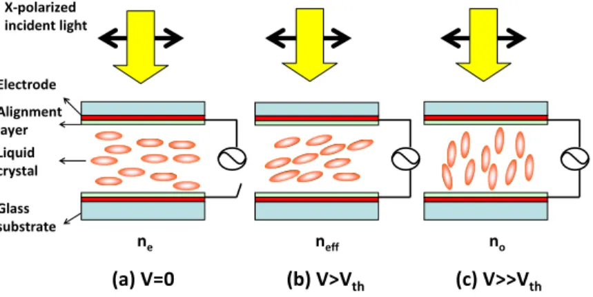
Nematic liquid crystals (LCs) are materials with rod-like structures whose electro-optical properties are anisotropic.1 Generally LCs are confined in a LC cell composed of two glass substrates coated with indium tin oxide (ITO) electrodes and alignment layers, as shown in Fig. 1(a)-(c). Figure 1 shows the electrically tunable refractive index of the LC cell. When the applied voltage (V) is zero, the long axes of LCs are parallel to the rubbing direction of the alignment layer. As a result, the x-polarized incident light experiences the extraordinary refractive index (ne), as shown in Fig. 1(a). As the applied voltage is larger than the threshold voltage (V> Vth), the applied electric field causes the induced dipole moments to the LC molecules and then induced a torque to change the orientations of LCs, as shown in Fig. 1(b). The linearly polarized incident light then experiences the effective refractive index of neff depending on the angle between the polarization of incident light and the long axes of LC directors. In Fig, 1(c), when the applied voltage is much larger than the threshold voltage (i.e. V>> Vth), the LC directors tend to parallel to the applied electric field to satisfy the lowest free energy of the system. The linearly polarized incident light experiences ordinary refractive index (no) in Fig. 1(c). The neff of the LCs in Fig. 1(b) can be expressed as:1
θ θ 2 2 2 2 sin cos 1 × + × × = e o o e eff n n n n n
,
(1) where θ is the tilt angle between the long axes of LC directors and the polarization of the incident light. From Eq. (1), the neff could be changed from ne to no as the tilt angle of θ increases with applying electric fields.Electrode Alignment layer Liquid crystal Glass substrate X-polarized incident light (a) V=0 (b) V>Vth (c) V>>Vth ne neff no
Figure 1 : The optical mechanism of electrically tunable refractive indices of liquid crystal cell. (a) At V=0, the polarization of the linearly polarized incident light is parallel to the long axes of LC directors and then the light experiences the refractive index of ne. (b)
At V> Vth, the polarized light experiences the refractive index of neff . (c) At V>> Vth, the polarized light experiences the refractive
index of no .
To mimic the optical properties of a solid lens using LCs, a lens-like phase difference of LCs can be arranged by means of the distribution of orientations of LC directors or the distribution of the refractive indices of LCs. The
wavefront of an incident plane wave propagating in a LC lens is then converted to a convergent or a divergent spherical wavefront. As a result, the LC lens can be a positive lens or negative lens. When the distribution of orientations of LC directors is adjusted by the applied electric fields, the curvature of the modulated spherical wavefront is electrically controllable, so that the focal length of the LC lens is also switchable which can not be achieved by the conventional solid lenses.
Basically, the spatially orientational distribution of LCs can be manipulated to realize the LC lens. However, combination of other factors can further extend the versatile design of LC lenses, such as orientations of LCs, inhomogeneous thickness of a LC layer, diffraction, and manipulation of the polarization states. Here, we classify the LC lenses into 4 groups based on different operating principles: 1) Gradient Index (GRIN) LC lenses with a homogeneous cell gap, 2) Non-GRIN LC lenses with an inhomogeneous cell gap, 3) Diffractive LC lenses, and 4) LC lenses controlled by polarizations. We also summarize polarization independent LC phase modulations for LC lenses.
2.1. Gradient Index (GRIN) LC lenses with a homogeneous cell gap
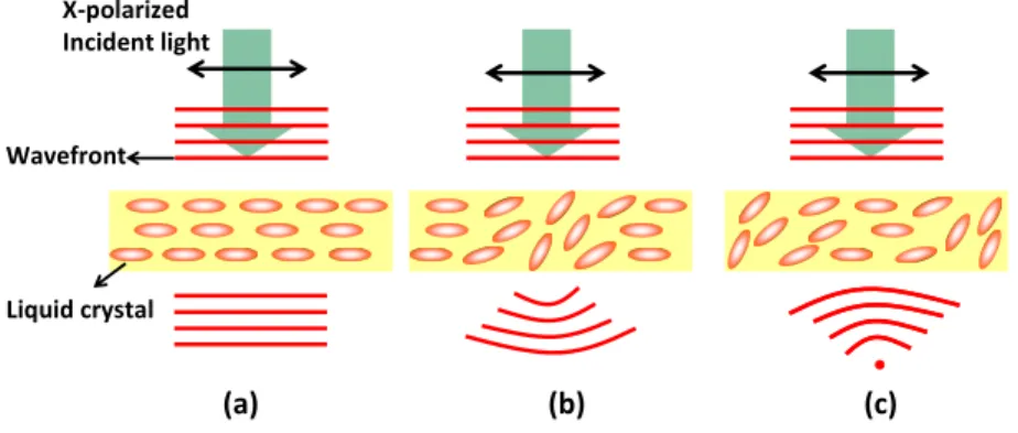
The operating principle of gradient index (GRIN) LC lens is illustrated in Fig. 2. In Fig. 2(a), the linearly polarized incident plane wave (i.e. x-polarized light in Fig. 2(a)) passes through a homogeneously aligned LC layer. The wavefront of the incident light remains the same. As a result, the focal length of the LC lens is at infinity. In Figs. 2(b) and (c), the wavefront of the incident light is bent by the LC layer because of the distribution of orientations of LC directors and then turns out a divergent or a convergent spherical wavefront. The LC cell acts as a negative lens in Fig. 2(b) or a positive lens in Fig. 2(c). The distribution of orientation of LC directors can be controlled by applying inhomogeneous electric fields. (a) (b) (c) X-polarized Incident light Liquid crystal Wavefront
Figure 2: The operating principle of gradient index (GRIN) LC lens with a homogeneous cell gap. (a) The LCs align homogeneously and the focal length of the LC lens is at infinity. The orientational distribution of LC directors results in a (b) negative
lensing effect and a (c) positive lensing effect
When the phase distribution induced by the LC lens is parabolic which means the LC lens acts as a conventional thin solid lens, the focal length of the LC lens can be expressed as:5
δ
λ
π
Δ
⋅
⋅
⋅
=
4
2D
f
,
(2) where D is the aperture width of the LC lens, λ is the wavelength, and the phase different (Δδ) between the rim andcenter of the aperture can also be expressed as:
d
V
n
V
=
⋅
Δ
⋅
Δ
(
)
2
(
)
λ
π
δ
,
(3) where d is the cell gap of the LC lens, Δn(V) is the difference of the refractive index between the center and the rim of the aperture. From Eqs. (2) and (3), the focal length of the LC lens depends on voltage due to the electrically tunable orientations of LC (or the refractive indices). Δδ can be positive or negative. The maximum of Δn equals to (ne – no).Therefore, the theoretical shortest focal length of the LC lens is
d n n D o e− ⋅ ⋅( ) 8 2
. We can apply inhomogeneous electric
fields to the LC layer in order to obtain a larger lens power (i.e. the inverse of the focal length), good image quality and avoid disclination lines in the LC lens.6 To generate such inhomogeneous electric fields to a homogeneous LC layer, 4 types of structure(or electrode) design are usually adopted:
1) The layer of ITO electrode is hole-patterned (with a buffering layer) or coated a thin layer with a uniform resistance (modal lens).7-21
2) The substrate is designed to possess some dielectric distribution.22-24 3) The layer of ITO electrode is curved.25-28
4) The layer of ITO electrode is pixelated.29-32
Moreover, the distribution of pretilt angles of LC directors in the LC cell can also cause GRIN lensing effect by means of the photo-alignment method or the polymer-stabilized method.33-40 The comparison of the mentioned techniques is listed in table I as well. The more detail comparisons are also listed in our previous published review paper.3 Structure /electrode Aperture (mm) Voltage Thickness (mm) Focal length (cm) Reference
Hole patterned electrode (Buffering layer) 2 <80Vrms 2.03 ∞~10cm [41]
Hole patterned electrode (Modal lens ) 5 <10Vrms 1.21 ∞~100cm [42]
Substrate with a hidden dielectric distribution
2.25 <20Vrms 1.58 ∞~10cm [24]
Substrate with a dielectric
Distribution (embedded Polymeric layer)
1.25 <2.6Vrms 1.25 ∞~47cm [22]
Curved electrode 6 <60Vrms 1.53 ∞~60cm [26]
Pixelated electrode 4 <10Vrms 1.25 ∞~200cm [30]
Pretilt angle/ Photo-alignment method 80 μm <1.8 Vrms 1.21 ∞~180cm [36]
Pretilt angle/ Polymer-stabilized method 1.55 <7.34 Vrms
Table I Comparisons of techniques for the inhomogeneous electric fields applied to a homogeneous LC layer. The thickness of substrates is assumed as 0.6 mm for the top and the bottom substrate.
2.2. Non-GRIN LC lenses with an inhomogeneous cell gap
Figures 3(a) and 3(b) show the operating principles and the structure of the non-GRIN LC lens with an inhomogeneous cell gap.43-48 The LC lens consists of a polarizer, a LC layer, the conventional concave glass lens and the planar glass substrate. Both of the glass lens and glass substrate are coated with transparent electrodes and alignment layers. The alignment layers are mechanically buffered in anti-parallel directions. The polarizer is used to filter out the ordinary wave of incident light. On a basis of geometric optics, the focal length of the LC layer with the curve surface (fLC) can be expressed as:43
1 ) ( − = V n R f eff LC
,
(4) where R is the radius of curvature of the concave glass lens, neff(V) is a voltage-dependent effective refractive index of the LC layer. The total focal length of the LC lens is composed of two sublenses: one is the LC layer and the other is the concave glass lens. The total focal length of the LC lens (f) can be written as:g eff g LC n V n R f V f f − = + = − ) ( ] 1 ) ( 1 [ 1
,
(5) where fg is the focal length of the concave glass lens, ng is the refractive index of the glass lens. In Fig. 3(a), the effective refractive index of the LC layer is ne at V = 0. When V>Vth, the long axes of the LCs tend to parallel to the electric fields. The effective refractive index of the LC layer is no, as shown in Fig. 3(b). From Eq. (5), the focal length of the LC lens can be changed from R/(ne-ng) to R/(no-ng) when the applied voltage increases. Since the focal length of the LC lens depends on the refractive indices, neff and ng, the positive lens or negative lens can be obtained depending on neff > ng or neff < ng. Because the refractive index of the conventional glass is usually smaller than LC, the LC lens is the positive lens. In order to switch positive lens to negative lens, we can choose proper materials whose refractive index is between ne and no of LCs. Moreover, we can choose a different glass lens with a different radius of curvature to adjust the focal lens of the LC lens.Glass Liquid crystal Alignment layer Electrode Polarizer (a) (b)
Figure 3: The operating principles of the LC lens with an inhomogeneous cell gap at (a) V=0, and (b) V> Vth.
12 N 10-C 16 ú $_16
i
$ 6-sN &) 4-to s a - Refractive - Kinoform diffractive Multilevel diffractivellilte..\\\\\\
-0 0 500 1000 1500 2000 Position, a.u.Many applications require LC lenses with large aperture (>1cm) and large tunable focusing range (infinity to 10 cm). For the conventional LC lenses based on only the electrically tunable distribution of refractive indices, large tunable focusing range requires the thicker LC layer and then results in scattering and slow response time of the LC lenses. The large aperture is still difficult to be realized. However, the diffractive LC lenses combining the tunable focusing properties of LC lens and the diffraction of Fresnel zone plate can not only minimize the thickness of the LC layer (the cell gap), but also enlarge the aperture size. As we can see in Fig. 4, the parabolic phase profile of the refractive lens (black line) requires large phase shift (~12 π radians) while the phase profile of the diffractive LC lens requires only ~2π radians (blue line and red line). The kinoform diffractive lens (blue line) provides an ideal phase profile with diffraction efficiency up to 100%. The phase shift of the diffractive lens (or Fresnel zone lens) optically equals to the phase shift of the refractive lens except the multiple of 2π radians. The phase jump between adjacent zones is 2π radians for the designed wavelength, and the outer radius of each zone can be expressed as:49
f
m
r
m=
2
×
×
λ
×
, (5) where m is a counting index of Fresnel zones starting from the center, λ is the wavelength, and f is the focal length. To realize such structure, digital multilevel diffractive lens (red line in Fig, 4) is proposed. The multilevel diffractive lens adopts subzones to fit the ideal phase profile. The diffraction efficiency can be around ~40.5%, 81.1%, and 95% for 2, 4, and 8 subzones, respectively. Therefore, the diffractive LC lens can provide tunable steps-focus with adjusting proper efficiency.50 Besides using GRIN lens and multi-electrode design to realize the phase shift distribution, we can also adopt the surface relief structure generated by photolithography.50-52 As to the chromatic consideration, the harmonic multi-order diffraction for different wavelength of LC diffractive lens was also proposed.52Figure 4: The phase profile of refractive lens (black line), kinoform diffractive lens (blue line), and multilevel diffractive lens (red line).
2-4. LC lenses controlled by polarizations
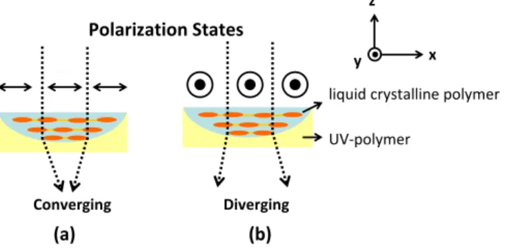
By adopting the anisotropic electro-optical properties of LC materials, tunable focusing properties of the LC lenses are switchable by switching the polarization states of the incident light. Figure 5 illustrates one of the operating principle of the polarization control LC lenses.53 The LC lens consists of an optically anisotropic liquid crystalline polymer layer
whose optical axis is parallel to the x-axis and an optically isotropic UV-polymer for flattening the structure of the LC lens. When the linear polarization of the incident light (a plane wave) is parallel to the x-axis, the light experiences the extraordinary refractive index of the liquid crystalline polymer, whose refractive index is usually larger than the refractive index of the UV-polymer. The focusing effect originates from an effect of combination of two sub-lenses: the lens of liquid crystalline polymer layer and the lens of UV-polymer. Therefore, the plane wave of incident light is converted to a converging wave/light, as shown in Fig. 5(a). On the contrary, when the linear polarization of the incident light (still a plane wave) is parallel to the y-axis, the incident plane wave is then converted to a diverging wave owing to the mismatch between the ordinary refractive indices of liquid crystalline polymer and UV-polymer, as shown in Fig. 5(b). The response time of the polarization control LC lens depends on the polarization switcher. Such polarization controlling LC lenses can also be achieved by different structures of LC lenses, and the advantages of this method can obtain short focal length (or large lens power) without sacrificing the response time.
liquid crystalline polymer Polarization States Converging Diverging UV-polymer (a) (b) x y z
Figure 5: The polarization control LC lenses.
2-5. Polarization independent LC lenses
Polarization dependency is a major concern for the applications due to the loss of light efficiency (~50 %). For achieving polarization independent LC lenses or polarizer-free LC lenses, many mechanisms of polarization independent LC phase modulations are developed.54 There are four main types of polarization independent LC phase modulations such as residual phase modulations,55-57 double-layered type structure,58-61 mixed type which is combined with residual phase type and double-layered type,62-63 and optically isotropic blue phase LC.64-65 In the residual phase type, all the LC directors have same tilt angle except their orientations are random. As a result, all the polarizations of incident light experience the same average refractive index of the LC layer. In double-layered type structure, to achieve polarization independence is to stack two identical homogeneous LC layers together in orthogonal directions. An unpolarized light can be decomposed into two linear eigen-modes, say x and y linearly polarized lights. After propagating through the two stacked LC layers, each eigen-mode experiences the same phase shift. Therefore, the phase shift of the double-layered type is polarization independent. The mixed type is mixed residual phase type and double-layered type in a LC cell. As to optically isotropic blue phase LC (BPLC), the mechanism is to adopt the electrically induced Kerr effect of BPLC and the propagating direction of incident light propagates along induced optical axis. Table II summarizes the performance of
the published polarization independent LC phase modulations or polarization independent LC lenses. Except the double-layered type LC phase modulations, others have smaller phase shifts.
Types LC modes Aperture
(mm) Cell gap (μm) Driving voltage (Vrms) Focal length (cm) Response time Year/ reference Residual phase type Polymer-stabilized cholesteric texture(PSCT) 0.44 26 <180 3.5~5 <0.8ms 2005 [55] Double-layere d type Two homogeneous LC layers 2.5 20 per layer <150 30~75 <1s 2005 [60] Mixed type Surface pinning effect of
polymer dispersed liquid crystals(SP-PDLC) 0.13 8 <200 1~14 <12ms 2011 [63] optical isotropic blue phase LC Polymer-stabilized blue phase liquid crystals(PS-BPLC) 0.25 20 <100 ∞~13.1 <3ms 2010 [64] Table II Summary of polarization independent LC phase modulations /LC lenses.
3. CONCLUSION
We have reviewed the LC lenses in this paper. The applications of LC lenses are versatile because the LC lenses possess the capability of tunable focusing properties without mechanical moving part. The applications of LC lenses can be applied to the imaging system,66 the projection system,67-68 the zoom system,69 the solar system,70 the ophthalmic applications,49,71 and the 2D/3D switching displays.72 By adopting two mode switching of the LC lens between a positive and a negative LC lens in a imaging system, the object located at infinity to 10 cm can be imaged electrically with fast response time <500 ms.66 By adding an extra LC lens in the pico projector, we can realize the electrically tunable focusing projection system.67 The LC lens can be used to electrically correct the size difference of colors in the holographic projection system.68 On a basis of the confocal system, the two LC lenses can further realize electrically tunable optical zoom system.69 The tunable focusing properties of a LC lens can be exploited to adjust the number of photons per area for solar cells in order to obtain a static electricity no matter what kind of sunlight condition is.70 The diffractive LC lenses can carry out the bifocal eyeglasses for presbyopia with large aperture size.49,71 We believe more applications of LC lenses are blooming.
REFERENCE
1. Yang, D. K., and Wu, S. T., Liquid Crystal Devices (Johon Wiley & Sons Ltd., 2006). 2. Ren, H, Wu, S. T., Introduction to Adaptive Lenses (John Wiley & Sons, Imc., 2012)
3. Lin, H. C., Chen, M. S., Lin, Y. H., “A Review of Electrically Tunable Focusing Liquid Crystal Lenses.” Trans. Electr. Electron. Mater. 12, 234 (2011).
4. Drzaic, P. S., Liquid Crystal Dispersions (World Scientific, 1995).
5. Kowel, S. T., Cleverly, D. S., and Kornreich, P. G., “Focusing by electrical modulation of refraction in a liquid crystal cell.” Appl. Opt. 23, 278 (1984).
6. Fowler, C. W., and Pateras, E. S., “Liquid crystal lens review.” Ophtal. Physiol Opt. 10, 186 (1990). 7. Sato, S., “Applications of liquid crystals to variable-focusing lenses.” Opt. Rev. 6, 471 (1999).
8. Ye, M., and Sato, S., “Optical properties of liquid crystal lens of any size.” Jpn. J. Appl. Phys. 41, L571 (2002). 9. Ye, M., and Sato, S., “Liquid crystal lens with focus movable along and off axis.” Opt. Commmu. 225, 277 (2003). 10. Ye, M., Wang, B., and Sato, S., “Liquid-crystal lens with a focal length that is variable in a wide range.” Appl. Opt.
43, 6407 (2004).
11. Wang, B., and Ye, M., “Liquid crystal negative lens.” Jpn. J. Appl. Phys. 44, 4979 (2005).
12. Ye, M., Yokoyama, Y., and Sato, S., “Liquid crystal lens with voltage and azimuth dependent focus.” Proc. SPIE 5639, 124 (2004).
13. Wang, B, Ye, M., and Sato, S., “Liquid crystal lens with focal length variable from negative to positive values.” IEEE Photonics Technol. Lett. 18, 79 (2006).
14. Ye, M., Wang, B., and Sato, S., “Effects of dielectric constant of glass substrates on properties of liquid crystal lens.” IEEE Photonics Technol. Lett. 19, 1295 (2007).
15. Ye, M., Wang, B., Yamaguchi, M., Sato, S., “Reducing driving voltage for liquid crystal lens using weakly conductive thin film.” Jpn. J. Appl. Phys. 47, 4579 (2008).
16. Ye, M., Wang, B., and Sato, S., “Realization of liquid crystal lens of large aperture and low driving voltages using thin layer of weakly conductive material.” Opt. Express 16, 4302 (2008).
17. Naumov, A. F., Loktev, M. Y., Guralnik, I. R., and Vdovin, G., “Liquid-crystal adaptive lenses with modal control.” Opt. Lett. 23, 992 (1998).
18. Naumov, A., Love, G. D., Loktev, M. Y., and Vladimirov, F., “Control optimization of spherical modal liquid crystal lenses.” Opt. Express 4, 344 (1999).
19. Love, G. D., and Naumov, A., “Modal liquid crystal lens.” Liq. Cryst. Today 10, 1 (2000).
20. Kotova, S. P., Patlan, V. V., and Samagin, S. A., “Tunable liquid-crystal focusing device. 1. Theory.” Quant. Electron. 41, 58 (2011).
21. Kotova, S. P., Patlan, V. V., and Samagin, S. A., “Tunable liquid-crystal focusing device. 2. Experiment.” Quant. Electron. 41, 65 (2011).
22. Lin, H. C., Lin, Y. H., “An electrically tunable-focusing liquid crystal lens with a low voltage and simple electrodes.” Opt. Express 20, 2045 (2012).
23. Wang, B., Ye, M., Sato, S. “Lens of electrically controllable focal length made by a glass lens and liquid-crystal layers.” Appl. Opt. 43, 3420 (2004).
24. Asatryan, K., Presnyakov, V., Tork, A., Zohrabyan, A., Bagramyan, A., Galstain, T., “Optical lens with electrically variable focus using an optically hidden dielectric layer.” Opt. Express 18, 13981 (2010).
25. Wang, B., Ye, M., Honma M., Nose, T., and Sato, S., “Liquid crystal lens with spherical electrode.” Jpn. J. Appl. Phys. 41, L1232 (2002).
26. Ren, H., F., Y. H., Gauza, S., Wu, S. T., “Tunable-focus flat liquid crystal spherical lens.” Appl. Phys. Lett. 84, 4789 (2004).
27. Ren, H., Fox, D. W., Wu, B., Wu, S. T., “Liquid crystal lens with large focal length tunability and low operating voltage.” Opt. Express 15, 11328 (2007).
28. Li, Y., Wu, S. T., “Polarization independent adaptive microlens with a blue-phase liquid crystal.” Opt. Express 19, 8045 (2011).
29. Riza, N. A., Dejule, M. C., “Three-terminal adaptive nematic liquid-crystal lens device.” Opt. Lett. 19, 1013 (1994). 30. Kao, Y. Y., Chao, P. C.-P., Hsueh, C. W.,“A new low-voltage-driven GRIN liquid crystal lens with multiple ring
electrodes in unequal widths.” Opt. Express 18, 18506 (2010).
31. Hsu, C. J., Chao, P. C.-P., Kao, Y. Y., “A thin multi-ring negative liquid crystal lens enabled by high-j dielectric material.” Mircosyst Technol 17, 923 (2011).
32. Millan, M. S., Oton, J., Perez-Cabre, E., “Dynamic compensation of chromatic aberration in a programmable diffractive lens.” Opt. Express 14, 9103 (2006).
33. Fuh, A. Y. G., Ko, S. W., Huang, S. H., Chen, Y. Y., Lin, T. H., “Polarization-independent liquid crystal lens based on axially symmetric photoalignment.” Opt. Express 19, 2294 (2011).
34. Honma, M., Nose, T., Yanase, S., Yamaguchi, R., Sato, S., “Liquid-crystal variable-focus lenses with a spatially-distributed tilt angles.” Opt. Express 17, 10998 (2009).
35. Tseng, M. C., F, F., Lee, C. Y., Muraski, A., Chigrinov, Y., Kwok, H. S., “Tunable lens by spatially varying liquid crystal pretilt angles.” J. Appl. Phys. 109, 083109 (2011).
36. Ye, M., Yokoyama, Y., Sato, S., “Liquid crystal lens prepared utilizing patterned molecular orientations on cell walls.” Appl. Phys. Lett. 89, 141112 (2006).
37. Presnyakov, V. V., Galstian, T. V., “Electrically tunable polymer stabilized liquid-crystal lens.” J. Appl. Phys. 97, 103101 (2005).
38. Ren, H, Fan, Y. H., Wu, S. T., “Polymer network liquid crystals for tunable microlens arrays.” J. Phys. D: Appl. Phys. 37 400 (2004).
39. Sergan, V. V., Sergan, T. A., Bos, P. J., “Control of the molecular pretilt angle in liquid crystal devices by using a low-density localized polymer network.” Chem. Phys. Lett. 486, 123 (2010).
40. Presnyakov, V. V., Asatryan, K. E., Galstian, T. V., Tork, A., “Polymer-stabilized liquid crystal for tunable microlens applications.” Opt. Express 10, 865 (2002).
41. Ye, M., Wang, B., Kawamura, M., Sato, S. “Fast switching between negative and positive power of liquid crystal lens.” Electron. Lett. 43, 474 (2007).
42. Love, G. D., Naumov, A. F., “Modal liquid crystal lenses.” Liq. Cryst. Today (2000).
43. Sato, S., “Liquid-crystal lens-cells with variable focal length.” Jpn. J. Appl. Phys. 18, 1679 (1979).
44. Dai, H. T, Liu, Y. J., Sun, X. W., Luo, D., “A negative–positive tunable liquid-crystal microlens array by printing.” Opt. Express 17, 4317 (2009).
45. Liu, Y. J., Sun, X. W., Wang, Q., “A focus-switchable lens made of polymer–liquid crystal composite.” J. Cryst. Growth 288, 192 (2006).
46. Ren, H, Fan, Y. H., Wu, S. T., “Liquid-crystal microlens arrays using patterned polymer networks.” Opt. Lett. 29, 1608 (2004).
47. Ren, H., Wu, S. T., “Polymer-based flexible microlens arrays with hermaphroditic focusing properties.” Appl. Opt. 44, 7730 (2005).
48. Ji, H. S., Kim, J. H., Kumar, S., “Electrically controllable microlens array fabricated by anisotropic phase separation from liquid-crystal and polymer composite materials.” Opt. Lett. 28, 1147 (2003).
49. Li, G., Mathine, D. L., Valley, P., Ayras, P., Haddock, J. N, Giridhar, M. S., Williby, G., Schwiegerling, J., Meredith, G. R., Kippelen, B., Honkanen, S., Peyghambarian, N., “Switchable electro-optic diffractive lens with high efficiency for ophthalmic applications.” PNAS 103, 6100 (2006).
50. Sato, S., Sugiyama, A., Sato, R., “Variable focus liquid -rystal Fresnel lens.”Jpn. J. Appl. Phys. 24, L626 (1985). 51. Fan, Y. H., Ren, H., Wu, S. T., “Electrically switchable Fresnel lens using a polymer-separated composited film.”
Opt. Express 13, 4141 (2005).
52. Lou, Y., Chen, L., Wang, “Tunable-focus liquid crystal Fresnel zone lens based on harmonic diffraction.” Appl. Phys. Lett. 101, 221121 (2012).
53. Choi, Y., Kim, H. R., Lee, K. H., Lee, Y. M., Kim, J. H., “A liquid crystalline polymer microlens array with tunable focal intensity by the polarization control of a liquid crystal layer.” Appl. Phys. Lett. 91, 221113 (2007).
54. Lin, Y. H., Ren, H., Wu, S. T., “ Polarisation‐independent liquid crystal devices.” Liq. Cryst. Today 17, 2 (2008). 55. Lin, Y. H., Ren, H., Fan, Y. H., Wu, Y. H. and Wu, S. T., “Polarization-independent and fast-response phase
modulation using a normal-mode polymer-stabilized cholesteric texture.” J. Appl. Phys. 98, 43112 (2005).
56. Ren, H., Lin, Y. H., Wen, C. H. and Wu, S. T., “Polarization-independent phase modulation of a homeotropic liquid crystal gel.” Appl. Phys. Lett. 87, 191106 (2005).
57. Ren, H., Lin, Y. H., Fan, Y. H. and Wu, S. T., “Polarization-independent phase modulation using a polymer-dispersed liquid crystal.” Appl. Phys. Lett. 86, 141110 (2005).
58. Wang, B., Ye, M., and Sato, S., "Properties of liquid crystal lens with stacked structure of liquid crystal layers." Jap. J. Appl. Phys. 45, 7813(2006).
59. Wang, B., Ye, M., and Sato, S., "Liquid crystal lens with stacked structure of liquid-crystal layers." Opt. Commun. 250, 266(2005).
60. Lin, Y. H., Ren, H., Wu, Y. H., Zhao, Y., Fan, J. Y., Ge, Z. and Wu, S. T., “Polarization-independent liquid crystal phase modulator using a thin polymer-separated double-layered structure. Opt. Express 13, 8746 (2005).
61. Ren, H., Lin, Y. H. and Wu, S. T., “Polarization-independent and fast-response phase modulators using double-layered liquid crystal gels.” Appl. Phys. Lett. 88, 61123 (2006).
62. Lin, Y. H. and Tsou, Y. S., “A polarization independent liquid crystal phase modulation adopting surface pinning effect of polymer dispersed liquid crystals.” J. Appl. Phys. 110, 114516 (2011).
63. Lin, Y. H., Tsou, Y. S., “A polarization independent liquid crystal microlens arrays adopting surface pinning effect of polymer dispersed liquid crystals.” J. Appl. Phys. 110, 114516 (2011).
64. Lin, Y. H., Chen, H. S., Lin, H. C., Tsou, Y. S., Hsu, H. K. and Li, W. Y., “Polarizer-free and fast response microlens arrays using polymer-stabilized blue phase liquid crystals.” Appl. Phys. Lett. 96, 113505 (2010).
65. Li, Y., Wu, S. T., “Polarization independent adaptive microlens with a blue-phase liquid crystal.” Opt. Express 19, 8045(2011).
66. Lin, H. C., Lin, Y. H., “A fast response and large electrically tunable-focusing imaging system based on switching of two modes of a liquid crystal lens.” Appl. Phys. Lett. 97, 063505 (2010).
67. Lin, H. C., Chen, M. S., Lin, Y. H., “An Electrically tunable focusing pico projector using a liquid crystal lens as an active optical element.” Mol. Cryst. Liq. Cryst. 544, 150 (2011).
68. Lin, H. C., Collings, N., Chen, M. S., Lin, Y. H., “A holographic projection system with an electrically tuning and continuously adjustable optical zoom.” Opt. Express 20, 27222 (2012).
69. Lin, Y. H., Chen, M. S., Lin, H. C., “An electrically tunable optical zoom system using two composite liquid crystal lenses with a large zoom ratio.” Opt. Express 19, 4714 (2011).
70. Tsou, Y. S., Lin, Y. H., Wei, A. C., “Concentrating photovoltaic system using a liquid crystal lens.” IEEE Photon. Technol. Lett. 24, 2239 (2012).
71. Smet, J. D., Avci, A., Beernaert, R., Cuypers, D., Smet, H. D., “Design and wrinkling behavior of a contact lens with an integrated liquid crystal light modulator.” J. Disp. Technol. 8, 299 (2012).
72. Chen, C. W., Huang, Y. P., Chen, P. C., “Dual direction overdriving method for accelerating 2D/3D switching time of liquid crystal lens on auto-Stereoscopic display.” J. Disp. Technol. 8, 559 (2012).