2754 IEEE PHOTONICS TECHNOLOGY LETTERS, VOL. 17, NO. 12, DECEMBER 2005
Improved SPM Tolerance and Cost-Effective
Phase-Modulation Duobinary Transmission
Over 230-km Standard Single-Mode Fiber
Using a Single Mach–Zehnder Modulator
Yu-Chang Lu, Jason (Jyehong) Chen, Kai-Ming Feng, Pao-Chi Yeh, Tzu-Yen Huang, Wei-Ren Peng,
Ming-Fang Huang, and Chia-Chien Wei
Abstract—This letter proposes and experimentally demonstrates
a cost-effective phase-modulation duobinary modulation scheme for improving self-phase modulation tolerance using a single mod-ulator. Successful transmission over 230 km of standard single-mode fiber was achieved.
Index Terms—Duobinary modulation (DBM), modulation
format, optical communication, prechirped modulation.
I. INTRODUCTION
R
ECENTLY, optical duobinary modulation (DBM) has received considerable attention [1]–[6]. Owing to the narrow spectral bandwidth compared with the typical nonre-turn-to-zero (NRZ) format, DBM has higher spectral efficiency, better chromatic dispersion tolerance, and less sensitivity to nonlinear effects. These benefits are crucial advantages for dense wavelength-division-multiplexed transmission systems. However, under high input optical power, the spectral width broadens rapidly during transmission due to the self-phase modulation (SPM) effect. Therefore, dispersion tolerance weakened rapidly with increasing input optical power [4], [5]. Prechirped DBM was first proposed in 1998, and the theoretical investigation was provided to explain the benefits of phase modulation [6]. Later, the phase-modulation DBM (PMDBM) was proposed to improve SPM tolerance by counterbalancing the effects of phase modulation, chromatic dispersion, and SPM [1]–[3]. However, in the new scheme, an extra modulator is often employed to provide the required phase modulation [2], [3]. An extra modulator increases transmitter complexity and cost, and hampers the use of this modulation format in cost-sensitive metro area transmission systems. This study proposes a novel PMDBM scheme for improving the SPMManuscript received May 9, 2005; revised August 21, 2005. This work was supported by the National Science Council of the Republic of China Taiwan under Contract NSC 93-2215-E-009-027, NSC 93-2219-E-007-001, NSC 93-2752-E009-009-PAE, NSC 93-2215-E-115-004, NSC 93-2215-E-115-005, and NSC 93-2752-E-007-002-PAE, NSC93-2752-E-009-004-PAE.
Y.-C. Lu, J. Chen, W.-R. Peng, M.-F. Huang, and C.-C. Wei are with the Institute of Electro-Optical Engineering and Department of Photonics, National Chiao-Tung University, Hsin-Chu, Taiwan 300, R.O.C. (e-mail: jchen@mail.nctu.edu.tw).
K.-M. Feng, P.-C. Yeh, and T.-Y. Huang are with the Institute of Communi-cation Engineering and Department of Electrical Engineering, National Tsing Hua University, Hsin-Chu, Taiwan 300, R.O.C.
Digital Object Identifier 10.1109/LPT.2005.859433
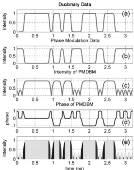
Fig. 1. (a) Electrical bit pattern of duobinary data, (b) electrical bit pattern of phase data, (c) optical intensity pattern after modulator, (d) optical phase pattern after modulator, (e) color encoded PMDBM data.
tolerance using only one modulator. Both the simulation and experimental results found a significant improvement in the performance of PMDBM. Successful transmission over 230 km of standard single-mode fiber (SSMF) was achieved.
II. PRINCIPLE OFOPERATION
The operating principle of the proposed scheme involves elec-trically combining the precoded duobinary and phase data and sending it into the dual-drive Mach–Zehnder modulator (DD-MZM). The output electric field can be written as
(1) where denotes the switching voltage of the modulator and and represent the dc bias voltages for arm one and arm
LU et al.: IMPROVED SPM TOLERANCE AND COST-EFFECTIVE PHASE-MODULATION DUOBINARY TRANSMISSION 2755
Fig. 2. Simulated (a) 0-km eye pattern of DBM, (b) 230-km eye pattern of DBM, (c) 0-km eye pattern of PMDBM, (d) 230-km eye pattern of PMDBM.
Fig. 3. Experimental setup of phase-modulation duobinary transmission system.
two, respectively. Moreover, and are the total voltages em-ployed on the two electrode arms. By selecting the polarity sent to the two arms, the duobinary data can be controlled to appear only on the intensity term and the phase modulation data can be controlled to appear only on the phase term. Con-sequently, use of a single modulator can enable simultaneous encoding of both the duobinary and phase information onto the optical signal. Fig. 1 shows (a) the detailed pattern of the normalized electrical duobinary data, (b) normalized electrical phase data, (c) normalized optical intensity of PMDBM, (d) nor-malized optical phase of PMDBM, and (e) nornor-malized optical intensity data of PMDBM with color-encoded frequency chirp. Although the inverted signal is displayed in Fig. 1(b), selection freedom exists using either data or in phase modulation signal. Additionally, Fig. 1(c) and (d) are the corresponding op-tical intensity and phase after PMDBM. Fig. 1(e) shows the fre-quency shift caused by phase modulation via color-encoded bit pattern. A blue shift exists at the rising edge and a red shift at the falling edge. By selecting the appropriated amplitude and polarity of the electrical phase bit pattern, the amount of phase modulation required to counterbalance the effects of SPM and dispersion under different optical powers and transmission dis-tances can be controlled.
Commercially available simulation software was used to con-struct a standard DBM and PMDBM transmission platform with input optical power of 13 dBm. Following 115 km of SSMF, an erbium-doped fiber amplifier (EDFA) is employed to com-pensate for the fiber loss, followed by another span of 115-km
Fig. 4. Experimental results of 66% driving voltage of (a) 0-km eye pattern of DBM, (b) 230-km eye pattern of DBM, (c) 0-km eye pattern of PMDBM, (d) 230-km eye pattern of PMDBM.
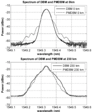
Fig. 5. Optical spectrum of 66% driving voltage of (a) 0-km DBM, (b) 230-km DBM, (c) 0-km PMDBM, (d) 230-km PMDBM.
SSMF. Fig. 2 shows the simulated eye pattern of (a) 0-km DBM, (b) 230-km DBM, (c) 0-km PMDBM, and (d) 230-km PMDBM, respectively. In Fig. 2(b), at high-power bit one, a very strong pulse narrowing effect due to SPM was noticed. Conversely, at low-power bit zero, a pulse spreading effect resulting from lack of SPM was observed. These phenomena are the reason for the eye closure. However, in Fig. 2(d), after applying phase modu-lation, a clean and open eye pattern was obtained. This clearly demonstrates that the phase modulation can effectively offset the effect of SPM.
III. EXPERIMENTALSETUP
Fig. 3 shows the experimental setup of the PMDBM trans-mission system. A 10-Gb/s pseudorandom binary sequence with length is sent into the duobinary precoder. The elec-trical signal then passes through a 2.5-GHz fifth-order elecelec-trical Bessel low-pass filter to generate the duobinary signal. The elec-trical duobinary and phase data then are combined using a
wide-2756 IEEE PHOTONICS TECHNOLOGY LETTERS, VOL. 17, NO. 12, DECEMBER 2005
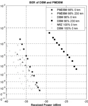
Fig. 6. BER of 66% driving voltage of 0 and 230 km of DBM and PMDBM, NRZ format and 100% driving voltage of DBM.
band (40 GHz) resistive combiner and sent into the DD-MZM for which the equals to 5.8 V. Owing to the insertion loss of the combiner (7.5 dB), the maximum driving voltage obtain-able following the combiner is 3.8 V for both the duobinary data and the phase modulation data, which corresponds to approx-imately 66% of the full swing voltage. The continuous-wave laser is a 40-mW distributed feedback laser with center wave-length at 1549.32 nm and the input optical power sent to the fiber is set to 13 dBm to ensure a large SPM effect. Following 115 km of SSMF, an EDFA is employed to compensate for the fiber loss and reset the optical power back to 13 dBm before the signal is sending into another section of 115-km SSMF. At the receiver, an optically preamplified receiver with an optical band-width of 0.32 nm was employed to remove the extra noise. For back-to-back measurements, the receiver sensitivity (bit-error ratio (BER) ) is 32 dBm. Fig. 4 shows the eye pat-terns of the 66% driving voltage of (a) 0-km DBM, (b) 230-km DBM, (c) 0-km PMDBM, and (d) 230-km PMDBM. Clearly, he phase modulation significantly impacts the eye pattern by main-taining the balance between SPM and dispersion. Fig. 5(a) and (b) shows the spectra of 66% DBM and PMDBM before and after transmission. Notably, PMDBM has a wider spectrum than DBM before transmission. Meanwhile, PMDBM has a narrower spectrum than DBM after transmission. Therefore, the phase modulation in PMDBM format can help to maintain a narrower spectrum. Fig. 6 shows the BER of 0- and 230-km transmis-sion of 66% driving voltage of DBM and PMDBM, respectively. Zero-kilometer NRZ format and 100% driving voltage DBM are also included as a reference. Compared with 66% PMDBM, error-free transmission cannot be obtained following 230 km of SSMF for both 66% and 100% DBM. Conversely, if an ap-propriate amount of phase modulation was applied, successful transmission over 230 km of SSMF was achieved. Comparing the proposed eye diagram with diagrams from the literature [3]
Fig. 7. BER of 66% driving voltage of DBM and PMDBM in linear and nonlinear power region following 230-km transmission.
revealed that the two appeared quite similar. Fig. 7 shows the BER plots of 66% DBM and PMDBM in linear optical input power region (i.e., 0 dBm) and nonlinear optical input power region (i.e., 13 dBm) following 230-km transmission. When re-duced the launch power to linear region, the sensitivity differ-ences between PMDBM and DBM diminish to less than 1 dB. However, PMDBM under nonlinear input power region has the best sensitivity that shows phase modulation can indeed improve the tolerance to SPM.
IV. CONCLUSION
This study has successfully demonstrated a novel PMDBM scheme to counterbalance the effects of SPM and dispersion using a single modulator. Successful transmission over 230 km of SSMF was achieved.
REFERENCES
[1] Y. Kim, H. Jang, J. Lee, I. Lee, M. Kim, and J. Jeong, “Improvement of SPM tolerance for phase-modulated duobinary transmission using phase modulator with postfiltering technique,” IEEE Photon. Technol. Lett., vol. 15, no. 12, pp. 1785–1787, Dec. 2003.
[2] H. Lee, H. Kim, J. Lee, S. K. Kim, G. Lee, S. Hwang, Y. Oh, J. Jeong, and G. Shim, “Cost-effective optical chirped duobinary transmitter using an electroabsorption modulated laser,” IEEE Photon. Technol. Lett., vol. 17, no. 7, pp. 905–907, Apr. 2005.
[3] M. Wichers, W. Kaiser, T. Wuth, and W. Rosenkranz, “Experimental demonstration of chirped duobinary transmission,” Electron. Lett., vol. 38, no. 4, pp. 191–193, Feb. 2002.
[4] L. Pierre, J. P. Thiery, and D. Penninckx, “243 km 10 Gb/s transmission experiment through standard fiber and impact of self-modulation using partial response scheme,” Electron. Lett., vol. 32, no. 7, pp. 673–674, Mar. 1996.
[5] W. Kaiser, M. Wichers, T. Wuth, W. Rosenkranz, C. Scheerer, C. Glin-gener, A. Farbert, J. P. Elbers, and G. Fischer, “SPM limit of duobinary transmission,” in Proc. ECOC 2000, vol. 3, Munich, Germany, Paper We 7.2.2, pp. 31–32.
[6] A. Djupsjobacka, “Prechirped duobinary modulation,” IEEE Photon.