Abstract — In the paper, we propose a novel scheduling mechanism without modifying the existing IEEE 802.11 MAC, called wireless Radio-Matching Protocol (RMP). It takes account of interferences in wireless mesh networks to achieve maximum spatial reuse by using pre-specified radio transmissions. In contrast with existing random access methods, The RMP adopts decentralized controlled access to avoid nodes from unintentional packet collisions. The RMP adopts a chain topology of bidirectional transmissions, where nodes are spaced so that radios of non-neighboring nodes do not interference with each other. Simulation results indicate that the throughput of RMP is about 30% better than that of Ripple [7] and almost 200% better than that of the IEEE 802.11 DCF. Although RMP achieves higher throughput than Ripple, it still maintains the same delay time and transmission quality, as verified by our simulation results. The RMP achieved a stable throughput and a low end-to-end transmission delay in both CBR and FTP traffic compared to the IEEE 802.11 DCF. In addition, the RMP is simple, easy to implement, and it eliminates the back-off inefficiencies and the collision problem in IEEE 802.11 wireless environments.
Index Terms — chain topology, interference, multi-hop, multi-radio, spatial reuse, wireless mesh network
I. INTRODUCTION
ireless mesh networks (WMNs) have emerged as a key technology and started an upsurge in the wireless research over the past few years [1]. Increasingly, WMNs are widely to provide connectivity to devices in the environments where wired network infrastructures do not exist or are expensive to deploy. Unlike mobile ad hoc networks (MANETs), where communications occur between any pair of nodes through mobile relaying nodes, WMNs provide a wireless backbone formed by non-mobile relaying nodes for nomadic users to access the wired Internet [7]. Instead of being another type of MANETs, WMNs diversify the capabilities of MANETs. This feature brings many advantages to WMNs, such as good reliability, high coverage, low upfront cost, and easy network maintenance.
WMNs are characterized by multi-hop radio broadcast environments, and spatial reuse can be used to increase the capacity of the networks. The medium sharing and the weakness of Carrier Sensing Multiple Access with Collision Avoidance (CSMA/CA) make the IEEE 802.11 Medium Access Control
1 This work was supported by the NCTU EECS-MediaTek Research Center under Grant Q583 and the National Science Council under Grant NSC94-2213-E-009-043.
(MAC) not fit the requirements of backhaul networking in WMNs [2]. The CSMA/CA mechanism for distributed access to the shared channel is extremely restrictive and prohibits any concurrent transmission or reception activities in the vicinity of either an active sender or receiver [6]. Therefore, in multi-hop environments, the interference problem causes long transmission delay and low throughput. Spatial reuse in a wireless network allows multiple communications to proceed simultaneously; hence observably improves the overall network throughput. The idea of spatial reuse is that several nodes, which are far enough in space, can make transmissions simultaneously in the same channel without a collision [3]. However, achieving maximum spatial reuse would require an ideal MAC protocol that schedules communications to maintain the optimal transmitter separation distance while minimizing interference. The performance of spatial reuse depends on various characteristics of the network, including the type of radio, network topology, channel quality requirements and signal propagation environment, etc. To increase the network performance, each backhaul router also needs to have its own scheduling module for sharing the transmission resources efficiently [2].
In this paper, we propose a novel scheduling mechanism without modifying the existing 802.11 MAC, termed as wireless Radio-Matching Protocol (RMP), to maximize the spatial reuse in WMNs and thus achieve better overall network throughput and higher spectral efficiency. The RMP uses pre-planning multi-radio mesh routers to form a chain and each radio is assigned a specific channel for transmitting or receiving only. With this deployment, the RMP has high spatial reuse by properly scheduling multiple transmissions in parallel to compose an efficient wireless backbone in WMNs.
The remainder of this paper is organized as follows. Section 2 discusses the related spatial reuse researches in WMNs. Section 3 presents the background of interference problems and the operations of RMP. The simulation results are shown in Section 4. Finally, Section 5 gives concluding remarks.
II. RELATED WORK
We first review existing MAC protocols that aimed to maximize spatial reuse in WMNs. The performance of IEEE 802.11 MAC protocol is not satisfactory in wireless multi-hop environments [2]. Without pre-planning, nodes in a wireless ad-hoc network rely on detect-and-transmit schemes to discover (re)usable channels [14]. The CSMA/CA algorithm is the basis of the Distributed Coordination Function (DCF) in the IEEE 802.11 [13]. A node attempting channel access defers for a
Efficient Spatial Reuse in Multi-Radio,
Multi-Hop Wireless Mesh Networks
1
Da-Ren Guo, Kuochen Wang and Lung-Sheng Lee Department of Computer Science
Nation Chiao Tung University Hsinchu, 300, Taiwan [email protected]
random period (backoff time) when it detects either a busy channel or a collision. Some nodes can suffer from severe throughput degradation in access to the shared channel when loads in the channel are high, which also results in unbounded medium access delay and unfair resource distribution for the nodes. There is a considerable interest in determining how the performance of such a MAC algorithm works in a multi-hop network.
A Wireless Token Ring Protocol (WTRP) [4][5] was proposed to eliminate the backoff inefficiencies and the collision problems in a ring topology. The WTRP is a distributed MAC protocol and partial connections are enough for full connectivity. The stations holding tokens take turns to transmit and are forced to suspend the transmission after having the medium for a specified amount of time. The WTRP supports guaranteed QoS in terms of bounded latency and reserved bandwidth which are crucial requirements of real time applications and are unavailable in an IEEE 802.11 network. Although the WTRP improves transmission efficiency by reducing the number of retransmissions due to collisions; however, the network is underutilized since spatial reuse is not adopted.
MACA-P – MACA-P is an RTS/CTS based MAC protocol [6], which enables simultaneous transmissions in WMNs. The key idea of the MACA-P is to allow neighboring nodes to synchronize their reception periods so that, at explicitly defined instants, one-hop neighbors can switch their roles between transmitting and receiving in unison. The MACA-P added a set of enhancements to the IEEE 802.11 MAC and obtained higher communication concurrency by adding extra information, such as control gap, in the RTS and CTS messages. A control gap between the RTS/CTS exchange and the subsequent DATA/ACK exchange was introduced to schedule the DATA transmissions at the end of the control gap to avoid unnecessary backoff time caused by RTS/CTS. MACA-P’s principal goal is the enhancement of the four-way handshake to allow parallel communications.
Ripple [7] is a wireless token-passing protocol for WMNs. Unlike random-access-based approaches, the Ripple used a controlled-access-based approach to prevent nodes from intentional packet collisions in WMNs. The Ripple considers a WMN with a chain topology, where nodes are equally spaced and radios of nodes that are not neighbors do not interfere with each other [12]. A frame type named Ready-To-Receive (RTR) is added to this protocol as a token. A node is allowed to send a
DATA frame only if it holds a token. With this specific token-passing scheme, the operations of transmission could be as the same as a ripple made by a pebble. Note that, in the Ripple, it assumed that both the transmission range and interference range are equal to one-hop radius. However, this assumption is not realistic and taking a higher interference range than the transmission range into consideration is necessary in the real world.
III. DESIGN APPROACH
A. Preliminary
A node in the chain topology may attain an optimal utilization of 1/3 by applying spatial reuse [12]. If each node in the chain topology can properly schedule its frame transmission interval, a data packet could be forwarded without interfering with each other by a multi-hop transmission. The chain topology can be easily generalized to be a tree topology and both topologies are mainly used by the public WMN deployment in Taipei city [7]. With the progress of hardware supports, the multi-radio technology is used to maximize the aggregate throughput by coordinating the operation of multiple wireless network cards tuned to non-overlapping frequency channels. A network node has multiple radio interfaces and each one owns its own MAC and physical layers, so communications in these radio interfaces can be totally independent. Providing each node with multiple radio interfaces has some advantages over one single radio interface: 1) nodes can transmit and receive simultaneously; 2) nodes do not need to synchronize with other nodes for the channel; 3) nodes do not need to modify the MAC layer protocol and maintain backward compatibility; 4) IEEE 802.11 interfaces are off-the-shelf commodity and the price drops rapidly, etc. In fact, one radio interface can have multiple channels in this case; but for simplicity of design and applications, one single fixed channel is usually applied in each radio interface [1].
There are three types of ranges related to packet transmission in the IEEE 802.11 MAC scheme [10]: 1) the transmission range (R): the range inside which nodes are able to receive or overhear the packet transmission; 2) the carrier sensing range (Rs): the range inside which nodes are able to
sense the signal, even though correct packet reception may not be available; and 3) the interference range (Ri): a new
transmission may interfere with the packet reception of nodes within its interference range. It is generally assumed that the transmission range is smaller than the carrier sensing range and the interference range, i.e., R < Rs, and R < Ri. In ns-2 [8], the
interference range is by default set to a value of Ri = 2.2R. This
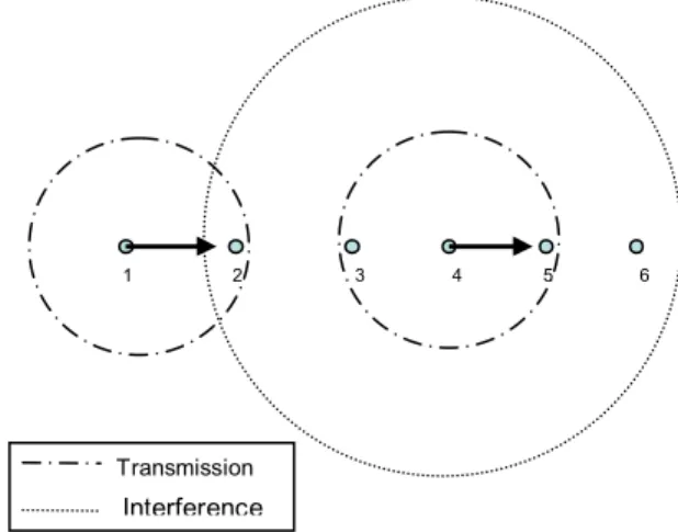
means that if we assign the transmission range as one hop distance, a node will interfere with nodes that are two hops far away; while at long enough distance, the interferences become negligible. Consider a network using a chain topology [12], as shown in Fig. 1, where node 1 is the source and node 6 is the sink. Nodes 1 and 2 cannot transmit at the same time because node 2 can not transmit and receive at the same time. Nodes 1 and 3 can not transmit at the same time because node 2 can not hear node 1 correctly if node 3 is sending. Nodes 1 and 4 can not send data at the same time because node 2 is within the interference range of node 4.
Interference
1 2 3 4 5 6
Transmission
However, we should consider a real situation: the situation becomes worse if one assumes that radios will interfere with each other beyond the range where they can communicate successfully. For example, in ns-2, it assumes that 802.11 nodes can correctly receive packets from nodes at 250 meters, but can interfere with nodes 550 meters away. Hence, in Fig. 1, packet transmissions of node 4 will interfere with RTS packets sent from node 1 to node 2. This prevents node 2 from correctly receiving node 1’s RTS transmission or sending the corresponding CTS. This is the main problem we intend to solve in this paper.
B. The Operation of the Proposed RMP
We propose a novel scheduling mechanism without modifying the existing IEEE 802.11 MAC protocol. This mechanism is applicable to chain-based and multi-radio WMNs. By means of matching radios between mesh routers, we name our pre-planning deployment and scheduling mechanism as a Radio-Matching Protocol (RMP), which can achieve the maximal spatial reuse. In the RMP, mesh routers are equally spaced to form a chain topology, where mesh routers that are not neighbors do not interfere with each other. Every mesh router is equipped with two wireless radio interfaces; one for transmitting and the other for receiving. In the RMP, there are two types of mesh routers:
1) T-R mesh router: For T-R mesh routers, the first channel is only for transmitting packets, and the second channel is only for receiving packets.
2) R-T mesh router: Similarly, for R-T mesh routers, the first channel is only for receiving packets, and the second channel is only for transmitting packets.
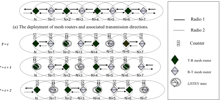
A chain is formed by assigning these two types of mesh routers alternately. That is, the neighbors of a T-R mesh router are R-T mesh routers. Similarly, the neighbors of an R-T mesh
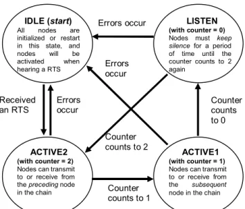
router are T-R mesh routers, as shown in Fig. 2 (a). That is, T-R mesh routers and R-T mesh routers are equally spaced such that the same types of mesh routers will not be neighbors. The transmission directions of each mesh router are also shown in Fig. 2. (a). The commonly used values for the transmission range and the interference range (250 m and 550 m) are adopted in both T-R and R-T mesh routers. In the following, we use mesh routers and nodes interchangeably. Fig. 3 shows the finite state machine of a mesh router using RMP. In the RMP, each node should be in one of three states:
z ACTIVE: A node enters this state when its counter counts to 2 or 1, and it can transmit and receive packets without interferences in this state.
z LISTEN: A node enters this state when the counter of this node counts to 0. Nodes in this state must keep silence for a period of time.
z IDLE: This state is used for initialization and error handling. When an error occurs during ACTIVE or LISTEN state, the node moves to this state to restart. Each node using RMP may transmit and receive packets for two time slots (in ACTIVE1 and ACTIVE2 states) and is then forced to suspend the transmission for one time slot (in IDLE state). Each node in this chain contains a simple counter, which counts 2, 1, 0, iteratively. That is, this simple counter counts from 2 to 1, 1 to 0, and 0 to 2 again. A node is allowed to transmit or receive a packet only if its counter counts to 2 or 1. Specifically, when a counter counts to 2, the corresponding node can transmit packets to and receive packets from the preceding node in the chain. When counting to 1, the corresponding node can transmit packets to and receive packets from the subsequent node in the chain. After having the medium for a specified amount of time, the counter counts to 0. During this period, the node does nothing but listens.
(b) The communication process of RMP in three consecutive time intervals.
Radio 1 Radio 2 N+6 N N+1 N+7 N+2 N+3 N+4 N+5 T = t N N+6 N+1 N+7 N+2 N+3 N+4 N+5 T = t + 2 N N+6 N+1 N+7 N+2 N+3 N+4 N+5 T = t + 1 T-R mesh router R-T mesh router LISTEN state N N+6 N+1 N+7N+2 N+3 N+4 N+5
(a) The deployment of mesh routers and associated transmission directions. 1 1 1 1 1 1 1 1 2 2 2 2 2 2 2 2 0 0 0 0 0 0 0 0 2 Counter
Fig. 2: A chain topology consists of two kinds of mesh routers that use the RMP scheduling to achieve the maximum spatial reuse.
The RMP initiates with the first node sending an activated packet to the last node in the chain network. The function of the activated packet is to awaken every node in the chain. At the beginning of the chain operation, each node is in IDLE state. A node (except the first node) is activated by an RTS frame generated by its preceding node in order to deliver the activated packet. After that it triggers its counter starting with the value of 2. This counter counts in sequence of 2-1-0 iteratively. A node has right to transmit or receive packets when its counter is not equal to 0. If a node is in LISTEN state, it just keeps silence. With the initiation of the first node, the RMP does not need a centralized control and can achieve distributed operation and synchronization. After the awakening phase of RMP, two nodes with a spatial-reuse distance [7] of three hops can transmit simultaneously without interfering with each other. Note that 2/3 nodes in this topology will be ACTIVE at the same time to accomplish the maximum network throughput. The communication process of RMP in three consecutive time intervals is shown in Fig. 2 (b).
The IEEE 802.11 DCF uses a 4-way distributed handshake mechanism to resolve contention between peers [13]. A node would transmit a CTS frame back after receiving a RTS frame; a receiver becomes a transmitter at this moment. By RMP, we ensure that nodes that are two hops-away will not be interfered. In Fig. 2 (b), when T = t, node N + 1 is transmitting and receiving packets, node N + 3 could be ACTIVE without interference from node N + 1 because node N + 1 and node N + 3 are using the same type of mesh routers. The interference caused by node N + 1 will not be sensed by node N + 3 because transmission and reception of these two nodes are in two non-overlapping channels. Therefore, we use an alternative radio pattern and an efficient distributed scheduling scheme to achieve the maximum spatial reuse. Problems caused by CSMA/CA, including the hidden terminal problem, exposed terminal problem and binary exponential backoff problem, which result in severe transmission problems in wireless multi-hop networks could also be resolved by using the proposed RMP. In summary, a node using RMP can achieve the optimal utilization of 2/3 under spatial reuse by resolving the interference problem.
IV. SIMULATION RESULTS
A. Simulation Model
The simulations of RMP were performed using ns-2 [8]. Each node in the RMP has two radios, and a single fixed channel is used in each radio. Communications in these two radios are totally independent. The two radios equipped in each node have an effective transmission range of 250 m, and the distance between nodes is 200 m. Considering the fact that each node may interfere with the data reception at another node, even though they are beyond the transmission range, a 550 m interference range was adopted in our simulation. The real time traffic and non-real time traffic, CBR and FTP, were used for performance evaluation. The link capacity is 1 Mb/s. A 1000-byte packet size and a 32-byte TCP Receiving Window were used when simulating FTP; the CBR simulation used various data rates and packet sizes [11]. Each sample was obtained by averaging 100 outcomes and each outcome was collected within 500 seconds [7]. Finally, network performance was evaluated by the end-to-end throughput and end-to-end delay.
B. Comparison with IEEE 802.11 DCF and Ripple [7]
We compared RMP with the IEEE 802.11 DCF and Ripple. The Ripple assumes both the transmission range and interference range are equal to one-hop radius. However, most of today’s IEEE 802.11 MAC implementations have a static interference range, or do not allow the interference range to be independently tunable [8][9]. As a result, taking the actual interference range of IEEE 802.11 devices with interference range into consideration is necessary and indispensable. With this concern, when a node in a chain topology with the circumstances that the interference range is almost 2.2 wider than the transmission range, it would interfere with nodes two hops away. Therefore, the spatial-reuse distance of the Ripple will be four hops away to prevent from unintended interference. For the RMP, the spatial-reuse distance could still be three hops because of the specific deployment of mesh routers. Due to mounting two radios to each RMP mesh router, we only evaluated the unidirectional throughput of RMP for fair comparison. Finally, we investigated the performance of IEEE 802.11 DCF, Ripple and RMP, and assumed that each node always had CBR or FTP traffic to transmit. We placed a gateway at each end of the chain, where the gateway acts as a source as well as a sink. In our simulation, the traffic source is always backlogged (i.e., offered load = 0.4 Mb/s) and the end-to-end throughput excluding the control overhead is evaluated at the sink node [7].
Fig. 4 shows the end-to-end throughput of CBR traffic for various chain lengths and different DATA frame sizes, where the source and sink nodes were located at two ends of the chain. For a chain with only two nodes, IEEE 802.11 DCF attained the maximum end-to-end throughput of about 0.82 Mb/s for 1000-byte frames, because there was no packet collision. However, the end-to-end throughput of IEEE 802.11 DCF for chains with more than two nodes decreased dramatically; at last, it dropped to 0.1 Mb/s as a result of excess collision with the increasing chain length. So the end-to-end throughput of IEEE 802.11 DCF is far less than that of the Ripple and RMP under spatial reuse. On the contrary, the Ripple and RMP always attained a stable throughput of 0.21Mb/s and 0.28Mb/s,
ACTIVE2 (with counter = 2) Nodes can transmit to or receive from the preceding node in the chain
LISTEN (with counter = 0) Nodes must keep
silence for a period
of time until the counter counts to 2 again
ACTIVE1 (with counter = 1) Nodes can transmit to or receive from the subsequent
node in the chain
Received an RTS Errors occur Errors occur Errors occur Counter counts to 1 Counter counts to 0 Counter counts to 2 IDLE (start)
All nodes are initialized or restart in this state, and nodes will be activated when hearing a RTS
respectively. Moreover, because the RMP achieves higher spatial reuse than the Ripple, the RMP has 31% higher throughput than the Ripple.
Fig. 5 shows the end-to-end throughput of FTP traffic for the three schemes under different chain lengths. The RMP and Ripple always offered more stable throughputs than the IEEE 802.11 DCF, and the end-to-end throughput of RMP is 29% higher than that of Ripple. The end-to-end transmission delay for various offered loads is presented in Fig. 6. We found that IEEE 802.11 DCF resulted in high end-to-end transmission delay with large variations. On the contrary, the Ripple and RMP had low end-to-end transmission delay even under high traffic loads.
0 0.1 0.2 0.3 0.4 0.5 0.6 0.7 0.8 0.9 2 3 4 5 6 7 8 9 10 11 12 20
Chain length (number of nodes)
E nd-to -e nd t hr oug hput ( M b/
s) 802.11: DATA = 1000 Bytes802.11: DATA = 500 Bytes 802.11: DATA = 64 Bytes Ripple: DATA = 1000 Bytes Ripple: DATA = 500 Bytes Ripple: DATA = 64 Bytes RMP: DATA = 1000 Bytes RMP: DATA = 500 Bytes RMP: DATA = 64 Bytes
Fig. 4: Chain throughput of CBR traffic for various chain lengths and DATA frame sizes
0 0.1 0.2 0.3 0.4 0.5 0.6 0.7 0.8 2 3 4 5 6 7 8 9 10 11 12 20
Chain length (number of nodes)
E nd- to-en d thr ough put ( M b/ s) 802.11 Ripple RMP
Fig. 5: Chain throughput of FTP traffic for various chain lengths and DATA frame sizes
V. CONCLUSIONS
The RMP is a novel scheduling mechanism, which does not modify the existing IEEE 802.11 MAC protocol, to improve spatial reuse in WMNs by using pre-specified transmission directions. The RMP provides bidirectional transmissions with the maximum spatial reuse and fault tolerance with two radios using a chain topology. It can achieve an optimal utilization of 2/3 by using two radios. The performance of RMP with real time traffic (CBR) and non-real time traffic (FTP) has been investigated and simulation results have shown that the throughput of RMP is about 30% better than that of the Ripple and almost 200% better than that of the IEEE 802.11 DCF. Although the RMP achieves higher throughput than the Ripple, it still maintains the same end-to-end delay and transmission quality. 0 0.05 0.1 0.15 0.2 0.25 0.3 0.35 0.4 0.45 0.1 0.15 0.2 0.25 0.3 0.35 0.4 Offered load (Mb/s) E nd- to-end de la y (s ) 802.11 Ripple RMP
Fig. 6: The mean end-to-end transmission delay for various offered loads.
REFERENCES
[1] I.F. Akyildiz and X. Wang, “A survey on wireless mesh networks,” in IEEE Communications Magazine, Volume 43, pp. 23 – 30, Sept. 2005. [2] T.-J. Tsai and J.-W. Chen, “IEEE 802.11 MAC protocol over wireless
mesh networks: problems and perspectives,” in Proc. Advanced Information Networking and Applications, Volume 2, pp. 60 – 63, March 2005.
[3] L. Fu, Z. Cao, and P. Fan, “Spatial reuse in IEEE 802.16 based wireless mesh networks,” in Proc. IEEE ISCIT, Volume 2, pp.1358 – 1361, Oct. 2005.
[4] M. Ergen, D. Lee, R. Sengupta, and P. Varaiya, “WTRP–Wireless token ring protocol,” in IEEE Trans Commun., vol. 53, pp. 1863 – 1881, Nov. 2004.
[5] E., M., D. Lee, R. Sengupta, and P. Varaiya, “Wireless token ring protocol-performance comparison with IEEE 802.11,” in Proc. IEEE IS, vol.2, pp. 710 – 715, 2003.
[6] A. Acharya, A. Misra, and S. Bansal, “Design and analysis of a cooperative medium access scheme for wireless mesh networks,” in Proc. BroadNets, pp. 621 – 631, 2004.
[7] Ray-Guang Cheng, Cun-Yi Wang, Li-Hung Liao, and Jen-Shun Yang, “Ripple: a wireless token-passing protocol for multi-hop wireless mesh networks,” in IEEE Communications Letter, Volume 10, pp.123 – 125, Feb. 2006.
[8] USC/ISI, “Network Simulator 2 (NS2),” [Online] Available: http://www.isi.edu/nsnam/ns/.
[9] J. Zhu, X. Guo, L.L. Yang, and W.S. Conner, “Leveraging spatial reuse in 802.11 mesh networks with enhanced physical carrier sensing,” in Proc. IEEE International Conference, Volume 7, pp. 4004 – 4011, June 2004. [10] J. Deng, B. Liang, and P.K. Varshney, “Tuning the carrier sensing range of
IEEE 802.11 MAC,” in IEEE GLOBECOM, Volume, pp. 2987 – 2991, Nov.-3 Dec. 2004.
[11] C.E. Seo, E.J. Leonardo, P. Cardieri, M.D. Yacoub, D.M. Gallego, and A.A.M. de Medeiros, “Performance of IEEE 802.11 in wireless mesh networks,” in Proc. IEEE MTT-S Conf., pp. 363 – 367, July 2005. [12] J. Li, C. Blake, D. S. De Couto, H. I. Lee, and R. Morris, “Capacity of ad
hoc wireless networks,” in Proc. ACM MobiCom, pp. 61 – 69, July 2001. [13] IEEE Std. 802/11, IEEE Computer Society LAN MAN Standard
Committee, Wireless LAN Medium Access Control (MAC) and Physical Layer (PHY) Specifications, 1997.
[14] X.G. Guo, S. Roy, and W.S. Conner., “Spatial reuse in wireless ad-hoc networks,” IEEE VTC, Volume 3, pp. 1437 – 1442, Oct. 2003.