國
立
交
通
大
學
資訊科學與工程研究所
碩
士
論
文
平行化系統虛擬機器設計與實作
PQEMU: Parallelizing System Virtual Machines based on
QEMU
研 究 生:張柏駿
指導教授: 徐慰中 教授
平行化系統虛擬機器設計與實作
PQEMU: Parallelizing System Virtual Machines based on
QEMU
研 究 生:張柏駿 Student:Po-Chun Chang
指導教授:徐慰中 Advisor:Prof. Wei Chung Hsu
國 立 交 通 大 學
資 訊 科 學 與 工 程 研 究 所
碩 士 論 文
A Thesis
Submitted to Department of Computer and Information Science College of Electrical Engineering and Computer Science
National Chiao Tung University in partial Fulfillment of the Requirements
for the Degree of Master
in
Computer and Information Science July 26, 2010
Hsinchu, Taiwan, Republic of China
平行化系統虛擬機器設計與實作
學生:張柏駿 指導教授:徐慰中國立交通大學資訊科學與工程研究所
摘
要
系統模擬器是一種快速評估、調整和驗證軟體原型的重要工具,其實用性取 決於其速度和準確性。現今流行的 QEMU 系統模擬器採用動態二進制翻譯來實現高 效能之系統模擬。然而其設計並無法有效利用潛在於軟體和底層硬體中的平行性。 本論文提出一個增強型設計 PQEMU,可有效地將多個虛擬 CPU 對應至實體多核心 上。實驗結果顯示此方法能有效提昇系統模擬器之平行性和擴展性。透過測試程 式 SPLASH-2 我們發現到在模擬一個四核心的 ARM11MPCore 系統於四核心 x86 i7 機器上時,PQEMU 最高可達到相對於原本 3.98 倍的效能增進。
PQEMU: Parallelizing System Virtual Machines based on
QEMU
Student: Po-Chun Chang Advisors:
Prof. Wei Chung Hsu
Department of Computer and Information ScienceCollege of Electrical Engineering and Computer Science National Chiao Tung University
ABSTRACT
A system emulator is an important tool to evaluate, debug and verify software developments before the real hardware systems become available. The key to a successful system emulator lies in its speed and accuracy in the emulation of the real machine. QEMU is a popular system emulator that adopts dynamic binary translation techniques to achieve high emulation efficiency. However, its current design takes no advantage of the parallelism available in guest applications and underlying hardware resources. In the current QEMU, simulation activities are going in serial, with a time-shared fashion. This thesis presents a parallelized QEMU, called PQEMU, which can uniformly distribute emulating jobs to underlying multi-cores. Our experiment results with PQEMU show that our design and implementation have significantly improved QEMU’s emulation performance on multi-core machines. Using the SPLASH-2 benchmark, PQEMU can be up to 3.98x faster than the original QEMU when emulating a quad-core ARM11MPCore system on a quad-core x86 i7 machine.
誌 謝
由衷感謝所有人的幫助。
張柏駿 2010 年 7 月
Contents
1 Introduction ... 1
2 Overview ... 5
2.1 Structure of a System Virtual Machine ... 5
2.2 Case Study: QEMU ... 7
2.2.1 Internal Data Structures in QEMU ... 8
2.2.2 From Guest Instruction to Target Machine Code ... 11
2.2.3 Reconstruct the Guest PC Address ... 14
2.2.4 Translation Output of a Memory Instruction ... 15
2.2.5 Protection for Translated Code ... 16
2.2.6 Chaining and Unchaining ... 16
2.3 Multi-Core Awareness ... 17
2.4 Engineering Challenges ... 20
3 Design and Implementation ... 25
3.1 Environment ... 25
3.2 Realization ... 25
3.3 Practices and Enhancements ... 37
4 Experimental Results ... 42
5 Related Works ... 54
6 Conclusion and Future Work ... 56
List of Figures
Figure 1: Virtual CPU Architectural states in QEMU ... 8
Figure 2: Memory address translation in QEMU ... 9
Figure 3: Structure of a code cache ... 10
Figure 4: How a code fragment is invoked by the VM manager ... 12
Figure 5: Calling a helper function inside a code fragment ... 13
Figure 6: Deliver a guest exception in QEMU ... 14
Figure 7: Example output of a guest load instruction ... 15
Figure 8: Branch at the last part of a code fragment... 16
Figure 9: Patching a branch destination on x86 machine ... 21
Figure 10: From guest processor to physical core ... 23
Figure 11: State diagram of QEMU events ... 27
Figure 12: Software layout in QEMU ... 28
Figure 13: Lock scheme in current PQEMU ... 32
Figure 14: Lock protection scheme in current PQEMU ... 33
Figure 15: Revised software layout for a dual-core guest in PQEMU ... 36
Figure 16: Vulnerability of lock attribute switch ... 37
Figure 17: The closure of an entry code fragment A for unchaining ... 39
Figure 18: Speedup in total execution time on QEMU ... 43
Figure 19: Speedup in total execution time on PQEMUs ... 46
Figure 20: Ratio of rdtsc counts excluding initialization ... 50
Figure 21: Ratio of rdtsc counts including initialization ... 51
Figure 22: Speedup in total execution time on ARM11MPcore ... 52
Figure 23: Speedup in computation time on ARM11MPcore and PQEMU-iolock-unserial-unchain ... 53
Table 1: Disposition of event combinations in PQEMU ... 30
Table 2: Experimental environment ... 42
Table 3: Total and computation time on QEMU ... 43
Table 4: Synchronization and total execution time on QEMU ... 43
Table 5: Total and computation time on PQEMU ... 44
Table 6: Total and computation time on PQEMU-iolock ... 44
Table 7: Total and computation time on PQEMU-iolock-unserial ... 45
Table 8: Total and computation time on PQEMU-iolock-unserial-unchain ... 45
Table 9: Synchronization and total execution time on PQEMU-iolock-unserial-unchain ... 46
Table 10: Internal event counts excluding initialization ... 48
Table 11: Internal event counts including initialization ... 49
Table 12: rdtsc counts of events excluding initialization ... 50
Table 13: rdtsc counts of events including initialization ... 51
1 Introduction
A multi-core processor is a processing system composed of two or more independent cores. The general trend in processor development has moved from single core to multi-core for several years. Nowadays it is difficult to find a server, a desktop, or even a laptop with a single core processor. It is expected that embedded systems will follow this trend soon [11]. Different from multi-processor in early days, such as the SMP (Symmetric Multi-Processors), buses and shared caches are now integrated onto the same chip with the multiple cores, thereby reducing the synchronization and communication latency between different cores. Although this new technology offers great potential for computing performance, such parallelism exists in hardware level and it relies on software to make good use of it. Numerous parallel algorithms have been developed, and the Operation Systems have exploited thread-level parallelism in addition to process-level parallelism. Both are trying to effectively exploit more parallelism of the underlying hardware computing resources. In practice, effective use of the parallel cores requires delicate engineering expertise and programming skills. To obtain an n-fold speedup of an application from an n-cores machine is a challenging and daunting task, not a trivial exercise.
A system virtual machine can support a guest OS along with its many user processes, and the guest architecture could have a different ISA (Instruction Set
Architecture). In this case, the virtualizing software must emulate the guest ISA on the host machine. QEMU is one commonly used system virtual machine. For example, it can be used to emulate an ARM MPCore system (guest) on an Intel x86-based system (host). A system virtual machine creates a computer environment within one another by one extra layer of software. Transparency of this layer determines how virtualization is realized: either by para-virtualization if the upper layer software, usually the guest OS, has a good knowledge of the existence of the virtualizing software, or it is called full- virtualization. Cooperation from the guest OS, as in the former approach, is for performance, but the guest OS must be modified to work with the virtualization layer. On the contrary, full-virtualization requires no changes to existing guest OS. In this thesis, we deal with full virtualization where an original Linux/ARM is emulated by the QEMU on an x86-based system.
Future embedded systems are likely to be built on top of multi-cores, and so are target systems to emulate. For example, we may like to study ARM based multi-core systems on a modern x86 platform. In order to understand the benefit from the power of multi-cores, the emulation in our system virtual machine must convey such parallelism as much as possible from the guest to the host on the physical cores. In other words, it is critical to arrange the emulation of each guest core as a thread executing on the host machine. So the emulation of multiple virtual CPU on the guest machine will become
multiple threads running on the multi-cores of the host machine. This thesis proposes a scheme that represents each guest core as a dedicated host thread which can be scheduled by the host OS independently. Threads for virtualized CPU can be easily identified by their strong computation demands, and a SMP-enabled host OS can schedule those virtual CPU threads properly on the underlying physical cores. Ideally, each process running on a virtual CPU could have its own parallelism to be exploited. The host system might have sufficient number of cores to handle a larger volume of emulation threads. For example, we might emulate an 8-core guest system on a four core host machine. However, we restrict our discussion in level of the system virtual machine, thereby less room will be given to the exploitation of further parallelism from the perspective of a thread or process.
In this thesis, the parallelization work is based on the versatile and popular system emulator QEMU [5]. QEMU adopts DBT (Dynamic Binary Translation) [16] techniques for fast ISA emulation. The emulator is working around a data structure called “code cache” which stores the translated code from the source ISA to target ISA for fast native code execution. To parallelize QEMU, we break all emulation activities into different events. The dependences between events are analyzed to determine how such events are synchronized. This design methodology gives us an enhanced thread-safe version of QEMU, named PQEMU. To mimic a more realistic design
scenario of a contemporary embedded system, we select ARM11MPCore as our guest system, and latest x86 multi-core system is our host. Although this work is built on top of QEMU, it is not specific to a particular design. Rationales for synchronization and serialization between events are applicable to all system emulators using DBT techniques. The experimental results using the well-known multi-threaded benchmark SPLASH-2 show that a maximum of 3.98x speedup achieved with our current PQEMU implementation running on the Intel quad-core i7 system. In addition, our PQEMU outperforms the real ARM11MPCore hardware by 181% to 372% when running the SPLASH-2 benchmark programs.
2 Overview
2.1 Structure of a System Virtual Machine
A System Virtual Machine (SVM) is a software layer capable of providing a virtual environment for the guest software (usually the guest OS). It comprises CPU, memory and IO modules in analogy to what a real computer has. In a hosted VM design, where the SVM is a user program inside the host OS, a virtual CPU is treated as a thread with additional memory for all guest architectural state, similar to the thread structure for OS context switch. Guest code execution is carried out through either interpretation, or dynamic binary translation, or the mixture of both. When the guest ISA is compatible with the host ISA, direct execution of native code can also be used for fast emulation. Interpretation is a straightforward approach to emulate a guest ISA, by mimicking the real hardware actions of fetch, decode, and execute in instruction sequence. However, interpretation is inefficient as most actions are redundant. To minimize redundancies, DBT [16] translates those guest instructions on-the-fly to correspondent target codes. The translation cost is high, but it is a one-time cost since the cost will be amortized over repeated execution such as in common subroutines or loops. Those translated codes are hold in a SVM-managed memory pool to prevent from re-translation. The memory pool holding the translated code is usually called code cache and in size of several megabyte. Emulation flows under such DBT-based framework can be separated
into several events such as: a) finding translated code fragment by the VM manager (generate if not exist), b) executing the code inside the code cache, and c) going back to the VM manager for next block of guest instructions. To decrease the frequency of going back to the VM manager and jump to a target block again, the branch destination at the end of a code fragment is often patched to what will be executed next in code cache (if it has been translated). This process is called chaining. The links between translated blocks will be gradually formed as time goes by, and eventually emulation will spend most of its time in code cache.
Guest memory is mapped to the virtual space of SVM. Although the functionality is preserved, their timing characteristics are lost. That means a FLASH memory access could be as fast as DDR from the emulation perspective in this environment. Besides, cache hierarchy on guest is often intentionally ignored, leaving the job of locality exploitation to the host hardware caches.
IO emulation is achieved through emulation functions, either completely inside SVM or in cooperation with the host. For instance, hardware timer is realized by the
SIGALARM-like timer facility and guest DMA requests are accomplished by memcpy()
calls. Different from real hardware, SVM could not properly deliver interrupts without temporarily breaking the execution in code cache. One might argue this could be emulated by intermixing such check-and-deliver code inside the translated code just
like what hardware exception mechanism will do, but that will end up in excessive checking as interrupts come infrequently and irregularly. A more efficient implementation is that SVM uses unchaining to break execution flow, which is a reverse process of chaining that restores final branch destinations to the VM manager. Another important issue for emulation is memory address translation, including conversion from guest physical to host virtual address mapping and the detection of memory-mapped IO (MMIO) accesses. A common solution is using software memory mapping, like a software controlled TLB, which deploys extra checking and mapping to satisfy all above requirements.
2.2 Case Study: QEMU
QEMU [5] is a well-known emulator for its flexible guest to host machine combinations and rich supports in IO devices. Though treated as a SVM in this work, it could function in Process Virtual Machine (PVM) mode too. QEMU adopts a simple compiler framework to do translation and apply some conservative optimizations. Different from earlier versions that deeply depend on template code with fixed register usage, today QEMU installs a register allocator to dynamically allocate host registers. QEMU is widespread on almost all platforms, and porting to a new machine is merely adding a guest frontend and/or a host backend. To reduce translation time during emulation, optimization algorithms applied are crafted in linear time complexity.
Memory address mapping is totally accomplished inside QEMU without any hardware intervention, i.e. using the access-trap-emulate scheme. To facilitate the conversion process, every guest core is equipped with a software managed TLB-like table. This implies the translation outcome of a guest memory instruction is consisted of a fast-hit and a slow-miss helper-calling path along with table lookup code at beginning, an approximately 20-fold increase in instruction count on the x86 machine. To distinguish MMIO requests from ordinary memory access, entries in TLB for IO are always marked invalid. Any read/write of such addresses will be redirected to the slow helper-calling path, and dispatched to IO emulation function. The overhead is high, and it is unsurprisingly poor in response time when compared to real hardware. The following subsections explain QEMU internals in detail by an example of a guest ARM machine on a generic x86 machine.
2.2.1 Internal Data Structures in QEMU
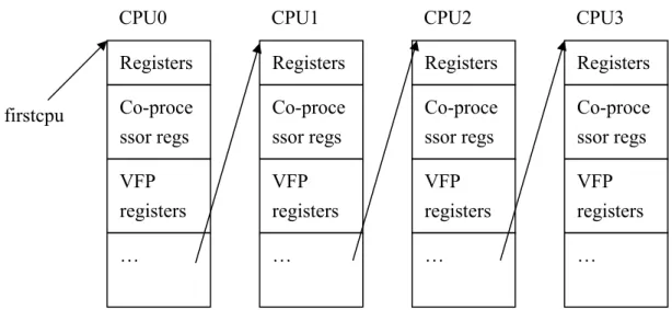
Figure 1: Virtual CPU Architectural states in QEMU CPU0 Registers Co-proce ssor regs VFP registers … CPU2 Registers Co-proce ssor regs VFP registers … CPU1 Registers Co-proce ssor regs VFP registers … CPU3 Registers Co-proce ssor regs VFP registers … firstcpu
1. CPU State: A memory block in SVM stores entire guest architectural state of each
virtual CPU with additional bookkeeping information. QEMU initializes all VCPUs as a linked list at startup time to reflect the cores in the guest machine. Example in Figure 1 shows the CPU states for quad-core ARM11MPCore system, where VFP stands for vector floating-point processor.
Figure 2: Memory address translation in QEMU
2. Memory and I/O: they are both initialized at guest machine peripheral setup phase.
Guest memory region is depicted by a malloced QEMU user space virtual memory. If there are FLASH and SDRAM in the source address space, two virtual memory chunks inside SVM will be allocated. IO devices are imitated through read and write device emulation functions, and their function pointers are collected in array IOread and IOwrite respectively. Address translation is illustrated in Figure 2, where the mapping is kept by a two-level table similar to the page table in OS, except that it is static after initialization. A bit field in second level entry is designated to distinguish regular memory references from MMIO accesses. If it is a MMIO address, the corresponded second-level entry would be an index to IOread and IOwrite; otherwise it is a pointer to virtual memory (there is one more layer for regular memory access to
Host OS Guest Virtual Address Guest Physical Address Host Virtual Address Host Physical Address Guest OS QEMU
achieve efficient code invalidation against Self-Modify Code (SMC). We skip that for simplicity). The TLB table deployed in every guest core accelerates the translation from Guest Virtual Address (GVA) to Host Virtual Address (HVA).
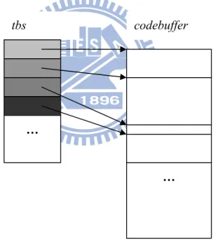
3. Code Cache: it consists of an identification array tbs and a buffer codebuffer for
output code fragments. ID is comprised of guest physical address (how fragment relates to guest machine code), flags (mainly for x86 segmentation), maintenance fields and pointer to real code fragment in codebuffer, say TBptr. codebuffer is simply a large byte array, usually in size of 16 or 32 Mega bytes.
Figure 3: Structure of a code cache
Forward lookup (finding translated code using guest PC address) is slow, as IDs are not sorted in key of GPA. A hash table with a linked-list is utilized to avoid linear search under this circumstance. In contrast, backward lookup (from pointer in
codebuffer to ID in tbs) is fast because code fragments are added to codebuffer one codebuffer
…
tbs
by one and therefore tbs are sorted in TBptr key. We will see the importance of backward lookup when reconstructing guest PC address.
Removing a code fragment is done by erasing TBptr and deleting ID from the hash table. After these two actions no one can find the removed code through tbs anymore. But target code still lives in codebuffer, and this ID entry is not recycled for new fragment unless codebuffer is full or no ID is available. If code buffer does overflow and no ID is available, then QEMU will trigger a flush and throw all code fragments away.
2.2.2 From Guest Instruction to Target Machine Code
QEMU uses a source-machine dependent frontend to convert input guest binary to internal IR, then it emits machine code through a target-specific backend. Before version 0.11.0, it is highly template-based, implying a strong dependency to a specific build of compiler. In later versions, it builds a simple compiler constructed into its code base, which performs register allocation, liveness analysis and constant propagation at runtime.
The structure of a code fragment usually starts with loading guest register values, then performs operations, and spills results back to its architectural state in SVM. Some registers are reserved for special purpose while others are free to use for emulation according to target ABI specification. For instance, %ebp on i386 target holds the
pointer to architectural state of guest core currently being emulated as a frame pointer; while %esp points to stack and others are free for computation (or subset to some peculiar instructions like ROtate-Right-register, which accepts only %ecx as its legitimate count register).
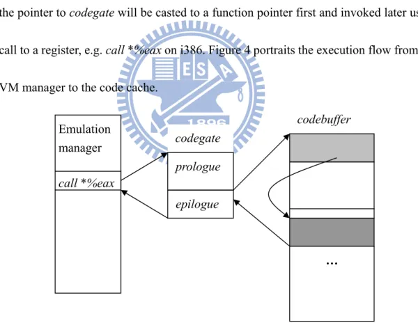
To preserve the C calling convention, common entry gate prologue and exit epilogue are generated to buffer codegate at the QEMU translation engine startup stage. This makes all code fragments look like leaf C functions to the VM manager, in which the pointer to codegate will be casted to a function pointer first and invoked later using call to a register, e.g. call *%eax on i386. Figure 4 portraits the execution flow from the VM manager to the code cache.
Figure 4: How a code fragment is invoked by the VM manager Some complex operations, particularly those interacting with QEMU internal data structures, are much easier to be implemented in C than in the translator IR (although it
codebuffer epilogue … Emulation manager call *%eax codegate prologue
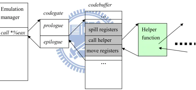
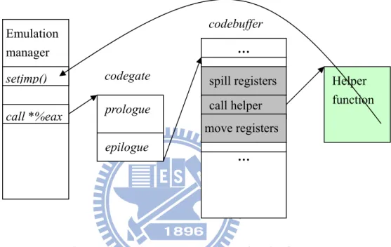
is good in speed and code size). QEMU introduces a special IR class, IR_CALL, to deal with the calling of a helper function inside a code fragment. Three segments of target machine code will be generated from the output emitter: I) spill all guest registers current on host registers (all caller-saved registers are included indeed), II) call helper function next, III) and last copy the result if any of destination registers does not match return registers (%eax and %edx by i386 ABI). Figure 5 illustrates a code fragment calling another helper function.
Figure 5: Calling a helper function inside a code fragment
Furthermore, helper functions that may generate exceptions and faults on guest machine might not move back to the calling code fragment. Precise architectural state is maintained by spilling guest register contents before the helper call in step I, and all intermediates within the helper are discarded (guest PC is the only exception that requires recovery. We will discuss it shortly). The disruption of guest execution flow is
codebuffer epilogue … spill registers call helper move registers … Emulation manager
call *%eax Helper
function
codegate prologue
realized through setjmp() and longjmp() library calls, similar to the exception handling mechanism in C++. Note that the interrupt delivery will never step in this path, as it is always synchronous to code fragment execution. Guest exception delivery in QEMU is shown in Figure 6.
Figure 6: Deliver a guest exception in QEMU
2.2.3 Reconstruct the Guest PC Address
For performance reason, the guest PC is updated only once at the end of a code fragment. For exceptions that disrupt normal execution flows, the guest PC may become inconsistent. QEMU dedicates a function cpu_restore_state() to recover the guest PC before calling longjmp(). Specifically, the return address of helper function obtained via GCC extension is exercised to find the calling code fragment by a backward search. QEMU retranslates this code fragment again with supplementary
codebuffer prologue epilogue … spill registers call helper move registers … Emulation manager call *%eax Helper function setjmp() codegate
knowledge about the mapping from the guest PC to target instructions (a one-to-many function). Then a trivial reverse range matching by the return address will reveal what exactly the guest PC is, and guest architectural state is fully restored at this moment.
2.2.4 Translation Output of a Memory Instruction
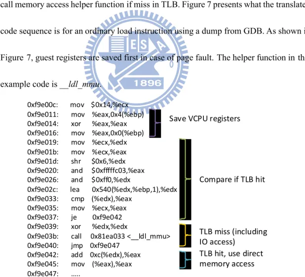
QEMU uses a direct-mapped software managed TLB to check for memory references. Three segments in the output code fragment will be generated for a normal memory access instruction: I) check for TLB entry, II) do a fast access if hit in TLB, III) call memory access helper function if miss in TLB. Figure 7 presents what the translated code sequence is for an ordinary load instruction using a dump from GDB. As shown in Figure 7, guest registers are saved first in case of page fault. The helper function in this example code is __ldl_mmu.
Figure 7: Example output of a guest load instruction 0xf9e00c: mov $0x14,%ecx 0xf9e011: mov %eax,0x4(%ebp) 0xf9e014: xor %eax,%eax 0xf9e016: mov %eax,0x0(%ebp) 0xf9e019: mov %ecx,%edx 0xf9e01b: mov %ecx,%eax 0xf9e01d: shr $0x6,%edx 0xf9e020: and $0xfffffc03,%eax 0xf9e026: and $0xff0,%edx 0xf9e02c: lea 0x540(%edx,%ebp,1),%edx 0xf9e033: cmp (%edx),%eax 0xf9e035: mov %ecx,%eax 0xf9e037: je 0xf9e042 0xf9e039: xor %edx,%edx 0xf9e03b: call 0x81ea033 <__ldl_mmu> 0xf9e040: jmp 0xf9e047 0xf9e042: add 0xc(%edx),%eax 0xf9e045: mov (%eax),%eax 0xf9e047: ….. Compare if TLB hit TLB miss (including IO access) TLB hit, use direct memory access Save VCPU registers
2.2.5 Protection for Translated Code
SMC (Self-Modifying Code) refers to writes to the memory of original guest instructions. Handling SMC is particularly difficult since they might have already been translated. In such a case, all translated codes in touch with the write address must be invalidated. To identify those offending writes, QEMU replaces the write entry of the two-level mapping table with an index to array IOwrite. The indexed write IO function performs a regular guest memory write together with code fragment invalidation. The write entry will restore to initial memory pointer if this page covers no translated guest code.
2.2.6 Chaining and Unchaining
The last part of a code fragment is a branch, either direct or indirect. Chaining will change the destination of a branch from exit to the VM manager to a code fragment to be executed next; while unchaining undoes it. The destination to an indirect branch is fed from a maintenance field of ID; whereas direct one embeds its target in itself. The instruction modification process for direct branches is similar to what the ELF dynamic loader resolves undefined symbols. Sample code is shown in Figure 8.
# Indirect Jump # Direct jump
mov ($field_address), %eax jmp $0xb85231ed jmp *%eax
Figure 8: Branch at the last part of a code fragment
change the destination. Direct branch is faster (a single instruction instead of two as for the indirect branch) but may suffer from limitations imposed by the host machine. For example, some architectures have limited range for direct branches, and some architectures lack atomic patches to branch instructions (due to variable length instructions). Chaining is easy as it is initiated by the emulation thread itself; but unchaining may originate from different treads, e.g. interrupt notification and exclusive access. To accommodate this, unchaining is solely invoked via SIGUSR1 signal. Sending a SIGUSR1 to a thread executing in the code cache will trigger the unchaining process and cause all branch targets of code fragments in closure (all code fragments can be reached from the current running code fragment) reverted to epilogue (leading straight to the VM manager).
2.3 Multi-Core Awareness
Multi-core is a trend that enables more efficient parallelism exploitation. To make use of duplicated hardware, SVM must extracts and exposes the potential of parallelism from guest directly to the target cores. On a parallelized SVM, target cores get better utilization if greater parallelism is exposed, and the virtual platform resembles real source machine better if host has many cores available. We discuss the impact to CPU, memory and IO components in the following.
architectural state for each virtual CPU. The design of the code cache is particularly important for achieving good performance and scalability. A Unified code cache can share all translated code fragments among all emulation threads; while a separate code cache keeps private copies, even at the cost of re-translation and extra memory space when some code blocks are shared between threads. The former is good in lower translation cost and memory overhead, and is also easier to implement since it is the current design in the sequential QEMU. However, the unified cache will suffer from greater contention amongst all virtual processors. Imagine that a thread for CPU A unchains itself for interrupts checking, but the same code fragment is being used by another thread for CPU B. A eventually receives incoming interrupt, and B falls back to the VM manager for unnecessary code fragment lookup that was originally chained. The latter gives us the chance for local tuning and improved code locality by placing hot code in clusters for a specific guest core. However, it is more complex to handle SMC, and more duplicated copies of code. SMC has been considered an infrequent event in applications. However, for SVM, SMC is not that uncommon. When guest OS needs to reclaim some memory, the old content must be cleared. Such activities are handled as SMC by the SVM.
Memory ordering is the key challenge when we move to address the issues of memory emulation. Atomicity imposed by source ISA must be enforced on target as
well, or the serialization primitives built atop might not work. For a weakly-ordered memory system, atomicity is enforced through a special kind of register-memory instructions; while strongly-ordered one extends to all memory instructions. Even a plain load-store instruction has to honor its program order. Because SVM has to insert explicit barrier after each guest memory access to guarantee the required order, we emphasize on weakly-ordered systems for the opportunity of optimization. These guest atomicity enforcing instructions are realized by either explicit spinlocks or simply exploit atomic instructions on target. The latter is preferred because of the brevity in code size and short locking time, but it is only applicable to semantically transformable guest atomic instructions. Those not suited for directly mapping to target atomic instruction will take the general spinlock approach.
IO also has a high impact to guest performance due to code unchaining activities for interrupt handling. One alternative for interrupt handling without unchaining is to insert explicit checking instructions in a loop. The checking instructions check if there are pending interrupts so that it can yield the execution control to the VM manager for interrupt delivery. While this scheme speeds up interrupt delivery, it slows down the normal program execution. After all, interrupts are supposed to be infrequent, and so we would rather let interrupt delivery pay the price.
2.4 Engineering Challenges
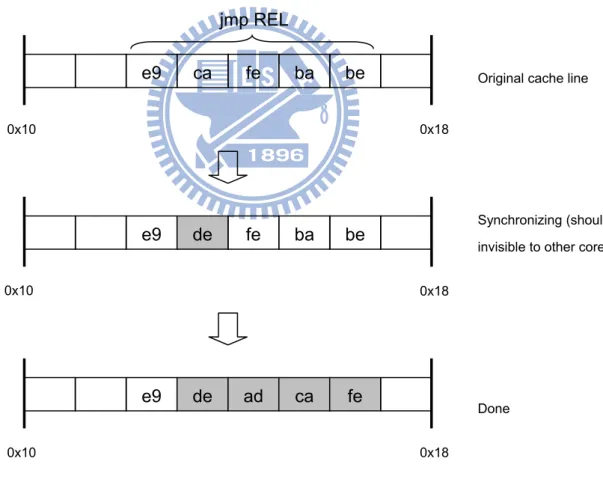
In addition to pseudo hardware components, there are some engineering issues deserve further discussion when parallelizing a SVM. First, the concurrency of chaining and unchaining happens inside the code cache. Since they will modify the destination bits of final branch instruction(s), concurrent execution of other threads in the code cache should be prohibited. Modified instruction bytes will go to data cache first when they are patched, and transfer to instruction cache later. For architectures that maintain coherence by explicit user request and has fixed instruction length, e.g. ARM, the worst case is out-of-dated I cache that branch still points to another code fragment when unchaining. Once the patched instruction propagates in, the execution flow will quit code cache and roll back to the emulation manager. The net effect is a late but functional unlinking, which is harmless to emulation threads and invisible to human being. But that is not the case if target is grounded on architecture with variable-length instruction and hardware-based synchronization mechanisms. Branch destination bits are usually not aligned on such machine, and partially-updated instruction may be seen by any other thread leading to an abrupt termination of illegal instruction fault. Consider the x86 target, for example, long jump instruction is expressed in a five byte sequence starting with 0xe9 and followed by 32-bit PC-relative distance to target. If the synchronization is carried out in unit of four bytes, two rounds of hardware-initiated
memory accesses will be used. If unfortunately the update is not atomic in respect to other cores, the SVM might crash for a wrong branch destination. For that reason, instructions in modification must be free of reference prior to (and in duration of) chaining and unchaining. Figure 9 illustrates the situation described above that a SVM turns the misaligned x86 branch destination bytes from 0xcafebabe to 0xdeadcafe, assume synchronization between I and D caches starts from lower address in unit of four bytes.
Figure 9: Patching a branch destination on x86 machine
The second one is thread scheduling on the host OS. A SVM basically has no idea about what the guest is doing now and whether a virtual core is busy or not.
e9 de fe ba be
0x10 0x18
e9 de ad ca fe
0x10 0x18 Original cache line
Synchronizing (should be invisible to other cores)
Done
e9 ca fe ba be
0x10 0x18 jmp REL
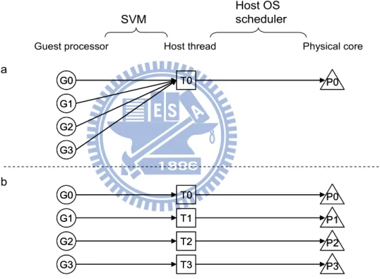
Consequently a SVM makes a conservative guess that all processors within guest machine are busy all over the time, which causes an interesting phenomenon that emulation threads are busy forever on host no matter in a busy calculation or an idle loop. The only exception is when some source architectural requests that explicitly wait for a hardware event or reveal clues about the current guest activity. For instance, wfi on the ARM architecture halts for interrupt coming and pause in x86 says the guest is waiting for a spinlock. But they are rarely used and some exist only in the guest kernel booting code. A serial SVM creates one host emulation thread even for multi-core guest for the sake of simplicity, on which the guest executions are carries out in a serial fashion sharing the same thread as in Figure 10(a). This time-sharing property is appreciated in early days where CPU chip has only one core. Multi-processor is indeed a composition of those single-core chips, and communication between processors is expensive due to the long path of onboard system bus. The idea of time-sharing is similar to OS scheduling, except it is operated on emulations of guest cores instead of thread contexts. These days the presence of multi-core on a die opens a door for extra performance boost, driving the emergence of more SMP-aware OS. With careful matching, paradigm that permits concurrent and evenly-dispatched thread executions on all physical cores could be established. For SVM, multiple emulation threads are spawned to act for guest multi-core. Host OS can identify these threads by their
computation-intensive signature (consume all allotted time slot), and bind them to every real cores in one-to-one manner by host scheduler as anticipated in Figure 10(b). However, that will incur a serious problem if parallelism in target is not sufficient to guest. The host scheduler will dominate the performance under this circumstance as less knowledge is attainable to guide computing resource sharing. Figure 10(c) shows a situation emulating a quad-core guest machine on a dual-core target.
Figure 10: From guest processor to physical core
The third one is the thread-safety of common resources, by either local duplication or lock deployment. The former tackles data structures that never removes
Guest processor Host thread Physical core
SVM Host OS scheduler G0 G1 G2 G3 T0 P0 G0 G1 G2 G3 T0 P0 G0 G1 G2 G3 T0 P0 T1 T2 T3 P1 P2 P3 G0 G1 G2 G3 T0 P0 T1 T2 T3 P1 P2 P3 G0 G1 G2 G3 T0 P0 T1 T2 T3 P1 G0 G1 G2 G3 T0 P0 T1 T2 T3 P1
?
a b cits element after initialization (at most adjust its internal position); while the latter is general to all shared objects. Fairness and waiting time of a lock are equally important to SVMs, as guest performance is very susceptible to any pause during emulation.
3 Design and Implementation
3.1 Environment
Our PQEMU is based on QEMU version 0.12.1. We choose ARM11MPCore [7] as our guest in the first implementation of PQEMU. It is a popular quad-core SMP in the embedded processor market and has been successfully integrated into Nvidia Tegra chipset [11]. As an heir of RISC, ARM is simple in terms of ISA design and features weakly-ordered memory system with few atomic instructions. Our host machine is a generic multi-core x86 system for its prevalence and abundance in hardware cores. A recent Intel i7 920 design equips with four independent cores and supports up to eight threads, more than the number of cores of the ARM11MPCore (thus avoid the situation portrayed in Figure 10(c)). In addition, x86 is (in)famous in diversity of instructions, which gives us better control over the output code quality under a high-register-pressure circumstance. For example, storing a constant value need not be a load immediate to register followed by the actual store; instruction store immediate suffices.
3.2 Realization
To get a systematic view of how QEMU works, we decompose it into a collection of events that are sharing internal resources (enumerated with short description about the activities and common objects involved):
compiler framework will be shared with the Restore event if code conversion engine is common to all emulation threads. A new code fragment, translated from the source guest code, will be added to the code cache.
Restore: for performance reason, guest PC is only updated once at the end of a code fragment. If a guest exception is generated in the middle of the code fragment, for example, a page fault from a memory instruction, the guest PC must be restored. This is done by means of table lookup or reconstruction to preserve precise guest architectural state. In practice, a SVM does not generate PC information in regular code fragments in order to reduce space overhead (QEMU adopts this strategy), and reconstruction using identical compiler framework in Build is used instead. See subsection 2.2.3 Reconstruct PC Address for detailed explanation.
Chain / Unchain: these two events involve instruction modification to code fragments. There are issues such as modify-when-use and synchronization between I and D caches if the code cache is shared. Subsection 2.4 Engineering
Challenge has more discussions on these issues.
Flush: the code cache is out of space and all translated codes will be abandoned immediately. This has been discussed in subsection 2.2.1 Internal Data Structures
cache, but that does not mean other threads can stay within because the subsequent Build will insert new blocks into code cache.
SMC: Self-Modifying-Code refers to changes made to existing guest code that has been translated. See discussion in 2.3 Multi-Core Awareness.
Find: locate translated code fragment using the guest PC. If the target block is not found, then invoke Build to translate and insert a new block to code cache.
Execute: emulation thread executes the code fragment found in Find or generated at Build as express in 2.2.2 From Guest Instruction to Target Machine Code.
Figure 11: State diagram of QEMU events
The flow of events is illustrated as a state transition diagram in Figure 11. The event Unchain (not shown in figure) is completely initiated by the SIGUSR1 signal handler in an asynchronous fashion, so it will intervene with all other events. Special treatments in lock acquiring for Unchain must be deployed, otherwise deadlock could
Find Flush Build Chain SMC Execute Restore
occur. The transition from SMC to Restore (dashed line) stands for self-invalidation that would happen when a code fragment writes data to the guest address of the source executable. It mimics the hardware synchronization mechanism between I and D cache (write instruction bytes to where the next PC points to in x86 for example). ARM does not support automatic I/D coherence enforcement. Therefore SMC to our guest ARM is purely code invalidation that never reaches Restore, only ends in Execute.
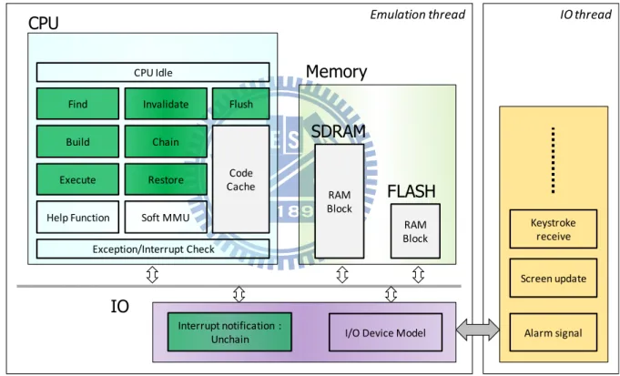
Figure 12: Software layout in QEMU
The overall software layout of QEMU is illustrated in Figure 12. Internal events are in green. QEMU allocated memories (code cache, SDRAM and Flash) are light grey, and other boxes are helper functions. CPU, memory and IO modules are included in emulation thread, and IO thread is responsible for interactions between QEMU and
Interrupt notification : Unchain RAM Block I/O Device Model Build Execute Restore Find Code Cache Soft MMU Help Function CPU Idle Invalidate Flush Chain Exception/Interrupt Check Emulation thread CPU SDRAM RAM Block FLASH Memory IO IO thread Alarm signal Screen update Keystroke receive
host OS. These activities are mostly SVM interface update (keyboard, mouse and screen) and guest hardware implemented using host system service (RTC timer).
From the perspective of hardware replication, providing multi-cores is fairly simple. QEMU has already reserved a memory pool for storing architectural states for each VCPU; memory and IO elements are shared among all VCPUs. Everything seems ready to go for parallel emulation. But QEMU still uses a sequential emulation model similar to Figure 10(a), and all guest cores are running in a non-preemptive time-shared fashion. This implementation simplifies the emulation of multi-cores in a lock-free setting and can handle the increment of guest core with ease. Shared components (mainly the code cache and derivatives) can be accessed without any contention; order and atomicity is preserved by round-robin and exclusive access of guest memory system. Likewise, core augmentation is merely additional memory allocation for new architectural state with a little bit of personalization in CPU ID or marking a portion of guest address space for core-private devices. However, target hardware resources are poorly utilized. The time received for actual core emulation is reversely proportional to the number of guest cores. Even worse, when all guest threads are evenly disturbed on all virtual processors, QEMU will suffer from slow guest code execution as no way to tell when and where a progress to guest code is.
at a time. PQEMU allows all emulation threads free to go like in Figure 10(b). The code cache and the translation engine are shared in the current PQEMU implementation. Translated code can be reusable among all emulation threads as each VCPU has its own architectural state in registers (the VM manager will do the setup before entering the code cache). Although contentions on the code cache may be there among different guest emulation threads, such incidences are relatively infrequent for many parallel applications. Besides, this implementation incurs less engineering effort since it requires no special effort to maintain the coherence of the code cache.
Write Event Read Event
Build Restore Chain Unchain Flush SMC Find Execute
Write Event Build S S X X S S S/X X Restore S S X X S S X X Chain X X S S S S X S Unchain X X S S S S X S Flush S S S S S S S S SMC S S S S S S S S Read Event Find S/X X X X S S X X Execute X X S S S S X X
Table 1: Disposition of event combinations in PQEMU
With parallel emulation, many events from different VCPU threads will happen simultaneously, serialization must be enforced for correct manipulation of the shared and writable objects. We tabulate all event combinations and their possible disposition
in Table 1, where S indicates a serialization and X means don’t care (free run). The following properties explain the reasons for serialized combination (marked S) in Table 1. Except read events (Find and Execute), all write events are in serialization with themselves (S on diagonal boxes of Table 1).
z Build and Restore shares the same translation engine, a lock is required.
z Eliminating a code fragment (Flush and SMC) is permitted only when it is not being referenced by another thread (Build, Restore, Chain, Unchain, Find and Execute). Except Build, all other five events operate on code fragment(s) in the code cache (even though it is for comparison in Restore to bring back fault guest PC address). A sudden removal of a code fragment will ruin their functionalities. Build is in the list because it will register identifiers for new code fragments and pointer to free code cache space before translation begins. In addition, Flush and SMC themselves are serialized to prevent incomplete code erasing.
z Execute and Chain / Unchain raise problems in target cache synchronization and code modification as stated above. A lock is required.
z Build and Find prevents the recurrence of code translation for the same guest address. This could be removed for better performance as such situations are rare and serialization here is truly an overkill. If serialization is taken away, there should be an extra check for validity of the code fragment during Restore, in case
at the same time another thread is in the Build state. No code invalidation will take place between two successive Build as Flush and SMC are in serial with all other events, and finally two code fragments to the same guest address will be. Redundant code fragment will be used once by generating thread and live solitary after without being reference anymore until die (Flush and SMC).
Figure 13: Lock scheme in current PQEMU
To effectively increase parallelism, performance, lock is applied in fine-grained control with weak or strong attribute. Strong lock equals to exclusive access in QEMU that keeps all other emulation threads out of the common code cache (equivalent to a pause), whereas the weak one corresponds to an ordinary lock that only the relevant access should get blocked. In another words, PQEMU effectively reduces the lock strength from a big strong one in the original QEMU to a few small and dispersed ones.
Find Build Restore Execute Chain Unchain Flush SMC
RWlock A – read lock RWlock A – write lock
Spinlock B Spinlock C
Figure 14: Lock protection scheme in current PQEMU
The lock scheme in PQEMU is illustrated in Figure 13, conforms to disposition in Table 1 that aggressively turns S in Build and Find to X. To prevent code fragments from being wiped out when they are in execution, RWlock A is used in read/write mode as the only weak/strong lock in PQEMU. Whenever a thread moves to a state that will refer to an existing code fragment, it must acquire the read-locked A beforehand. The Flush and SMC are fulfilled at the meantime by acquiring the strong write-lock A, indicating no threads are allowed to run at the same time. Read-locked A is acquired at beginning of the VM manager (transition to state Find in Figure 11) and is released at the end of emulation cycle (on way back to Find). Although theoretically they can be guarded in finer granularity of code fragment, we treat the entire code cache as one unit for engineering simplicity. Spinlock B protects common compiler related data
Legend
—Write lock A —Read lock A —Spinlock B —Spinlock C — No lock Find Flush Build Chain SMC Execute Restore Unchainstructures, and spinlock C serializes the requests of instruction modifications from Chain and Unchain. Emulation thread must grab read-locked A prior to acquiring B or
C for Build / Restore or Chain / Unchain to keep the code fragment from being wiped
out, or simply transfer to write-lock A if it moves to Flush or SMC state. The whole lock protection scheme is illustrated in Figure 14. With hierarchical lock layout, we are free of deadlock and concurrency of shared objects is preserved across all emulation threads.
Next, we discuss issues with memory. As to the weakly-ordered memory architecture, the question would be how to effectively enforce atomicity source ISA imposed on the target machine. ARM defines mainly two atomic instruction groups based on swap and exclusive mechanisms. The swap instruction swp acts similar to exchange instruction xchg in x86, except it could function on two distinct registers (one source, and one destination register). That excludes the chance realizing swp using xchg directly, unless both destination and source registers are identical. PQEMU realizes this coalesced memory load and store by designating a common spinlock X (different from those in CPU) at initial part of swp, analogous to the effect of #LOCK prefix in x86 and
#ASSERT on ARM. But it will occupy the whole system bus and could be a serious
limit to scalability. A more elaborated approach for exclusion in ARM is introduced after ARMv5. The new approach is similar to load-linked and store-conditional pair on
MIPS (i.e. ldrex and strex). A common table is arranged to record any load-linked address that is still waiting for a closing store-conditional instruction, and address will be erased if it is in collision with a subsequent store address. Any store-conditional with address not in table is regarded as a failed attempt that no data will be written to memory, and the unsuccessful value will be returned. However, monitoring all store instructions by software in PQEMU is inefficient and costly. A compromise is made that appends content snapshot into the entry of a table. If strex operates on an address not in the table or data in guest memory does not agree with snapshot made in time of ldrex, this trial is unsuccessful. We defer the generations of such guest atomic instructions till final code emitting stage to avoid the issues of larger code size and complex control if code generation was performed with IR at earlier stages. Dedicated emitters are akin to ones for ordinary memory access, except it will insert additional spinlock code for common table at the start and end of output code fragment. Sequence of execution will be determined by target hardware at run-time like what it is in real machine rather than predefined by QEMU. This resemblance is a giving for emulator in testing of a multi- thread program, a scene round-robin emulation model (Figure 10(a)) could never reach (even if aggressively in random ordered, it is sequential from the scope of executing guest instructions). PQEMU honors guest program order in translation, and there will be no memory reordering in output code fragments as PQEMU knows nothing about
the aliasing.
Last, N-N interrupt delivery model is supported by ARM11 multi-core processor, where all cores are informed simultaneously as soon as receiving an interrupt. Hardware could achieve this by asserting a signal wire within one cycle, but QEMU can only notify all emulation threads in sequential, which leads to an unbalanced utilization. PQEMU fixes this by asserting all core-private interrupt-notification flags in a round- robin order of guest cores, making request serving less unfair.
Figure 15 shows the revised software layout in PQEMU for a dual-core system (we omit the detailed boxes for simplicity). Most modules are identical to unmodified QEMU (Figure 12), except there are multiple emulation threads for system with multi- core support and the code cache is shared among (denoted by unified to distinguish with the separate alternative).
Figure 15: Revised software layout for a dual-core guest in PQEMU
Emulation thread #1 CPU 1 Memory IO IO thread Emulation thread #0
CPU 0 Unified Code
Cache
3.3 Practices and Enhancements
Special care must take to accommodate the transition from weak to strong lock (currently Find to Flush and Execute to SMC). Other than basic read-release write-
acquire sequence (solely a write- acquire will result in deadlock). Such pattern has a
pitfall in lock coverage time that interval between release and acquire is empty of lock protection. Any assumptions made in read stage should not be inherited in write phase. Figure 16 demonstrates a destructive case that code fragment Z will be invalidated due to SMC and read lock is released in thread 1. Thread 2 takes over immediately after a long wait and delete Z for Flush. Thread 1 operates on identification of code fragment Z later, but ends up in error as everything about code cache is gone. To fix it, thread must check Z again right after write lock is grabbed. If Find is serialized with Build, same problem will in transition from strong to weak lock (fortunately not in current PQEMU implementation).
Figure 16: Vulnerability of lock attribute switch Thread 1
Thread 2
Read release Check code
fragment Z Operate on code fragment Z
Write acquire
Read release Delete code
fragment Z
Write release Write acquire
Wait
Wait
Read protected Write protected
Read protected Write protected Wait for read
To cut the waiting time for write lock A, SIGUSR1 will be sent to all other threads, forcing them to leave the code cache and release the read lock. Spinlocks are furnished with random wait (by pause instruction on x86) when busy to alleviate contentions. Conventional strategy of spinlock locking under the assumption that pending time will be short is simply waiting till it is vacant. But the time spent in the VM manager is comparable to the time spent in the code cache by PQEMU, even when chaining is activated (ignore the case of chained loop). Idle-waiting becomes less economic in situation host cannot tell which emulation thread has a higher priority than others. All available time slots for waiting threads will be consumed in useless lock trying, and spinlock will be biased in favor of someone. To compensate for that, optional operations in PQEMU will be bypassed by try-lock spinlock call instead. This strategy is selectively applied to Chain and Unchain as both are performance-related events, not for correctness of PQEMU. As to the only read-write lock, pthread will yield voluntarily to the host scheduler if busy and starvation is evaded by flavor of preferring-
writer attribute. The whole locking facilities in PQEMU are rather efficient, especially
when booting up the guest Linux.
In general, events involving code removal must go with strong lock, while the rest are left for the weak ones. Chain / Unchain, the major performance hurdle in shared code cache design, are exceptions. Before shifting to Execute, the VM manager will try
to connect previously executed code fragments with the current one in Chain state. But only the regular two-way branch might succeed in this block-based DBT system, where each code fragment is ended in a guest branch instruction. To assure proper handling of guest page faults, chaining across page boundary will be inhibited. Otherwise just one thread, which usually the one triggers translation, will undergo guest page fault that loads a portion of program in unit of page into the guest main memory. Unchain will happen in any occasion as long as SIGUSR1 is received. It acts on a closure of code fragments defined by the first entry the VM manager found, because locating exact code fragment being executed is almost impossible once the thread dives into the code cache (stack unwinding to filter out helper function callings for complex procedures is a solution to normal program context, but it is inaccessible for signal handler context and its descents). Figure 17 illustrates the unchaining on a closure of code fragments, where all possible links within the closure will be restored to the VM manager during event Unchain.
Figure 17: The closure of an entry code fragment A for unchaining
Entry point A
PQEMU conservatively halts all other in-code-cache emulation threads by an idle waiting signal SIGURG for Chain and Unchain. SIGURG is registered with a signal handler trying to grab spinlock C. However, spinlock C is already held by initiator of Chain or Unchain at the time the handler is called. Thus, threads receiving SIGURG will deviate themselves until Chain or Unchain is done, and the synchronization problem between target I and D cache mentioned before is naturally avoided. Despite reducing the emulation path, this break also helps minimizing the surge of coherence invalidations from the x86 cache hierarchies if others are still executing in the code cache (note that the unit for cache invalidation is a cache line). Sharing code cache also makes Unchain easier as the effect of unchaining is visible to all emulation threads.
Chain and Unchain is expensive, and we address this problem in three directions. First, unnecessary unchaining is avoided, especially the ones for IO interactions between SVM and the host OS (boxes in IO thread of Figure 12). Original QEMU aggregates those activities into a dedicated IO thread, which will disrupt active emulation threads by endless unchaining requests until the emulation threads release the token for execution (i.e. a common mutex lock). This serialization is not mandatory since all tasks on IO thread are merely screen-update, keystroke-receive and mouse-move. Second, we try to shrink the size of a closure at unchaining. On modern POSIX-compliant OS, a signal handler has a new interface to obtain the additional
information about user context being interrupted. With the host PC value in context structure, the code fragment being executed can be recognized through reverse mapping. . Although not always accurate due to helper function calling (PC value is definitely out of the range of code cache), it is noteworthy in reduction of closure size. Third, the purpose of Unchain is to relinquish the usage of code cache instead of annihilate a code fragment. As the branch destination modified by Chain and Unchain is entirely bouncing between the VM manager and the next code fragment in PQEMU, we alter only the branch destination (instruction itself) when unchaining. Linking information for maintenance resided in the fields of code fragment identifier is kept in chained-state if the code fragment is chained before. Although Unchain still needs spinlock C in PQEMU, it is less expensive after the aforementioned optimizations.
4 Experimental Results
Experimental environment Benchmark Splash‐2
Guest OS Linux 2.6.27 arm_v6
Guest machine ARM11MPCore (4 cores SMP processor) Emulator PQEMU based on QEMU 0.12.1
Host OS Linux 2.6.31.12 x86_64 (Fedora 12) Host machine Intel Core i7 920 (quad core with 8 SMT)
Table 2: Experimental environment
The experiment environment is shown in Table 2: a guest ARM11MPCore is emulated on an Intel Core i7 920 host by PQEMU. 12 programs in the SPLASH2 [13] benchmark suite are chosen for PQEMU performance evaluation. They are highly parallelized programs, and we run them in configuration of one, two and four computing threads (we use number to distinguish them in following tables). All programs are compiled in ARMv6 ISA, and the time will be measured in unit of microsecond. The standard in-package input test set and default arguments are used in performance evaluation, except FFT with –m20, LU_NON with –n512 and RADIX with
-n1048576 to obtain a longer execution time (minimize the impact of initial
single-thread startup). We evaluate both unmodified QEMU and PQEMU in the emulation of the quad-core ARM11MPCore system. There are two host threads in QEMU and five in PQEMU (the additional one stands for IO thread in Figure 12 and 15). Since the IO thread is idle most of the time and there are eight hardware threads
(due to hyper threading in the i7 processor), the execution is not suffered from situation depicted in Figure 10(c). Computation 1 2 4 Total 1 2 4 LU 11,956,862 12,043,158 12,143,627 12,630,126 12,718,143 12,823,751 LU‐NON 13,440,032 13,507,292 13,578,076 13,864,701 13,941,957 14,014,652 OCEAN 17,890,290 17,873,450 18,129,541 29,415,089 29,566,996 30,202,861 OCEAN‐NON 18,123,181 18,019,329 18,405,727 29,184,820 29,189,187 30,020,996 FFT 20,480,395 20,563,329 20,589,159 36,293,727 36,367,771 36,394,870 BARNES 95,543,726 96,087,091 96,804,383 191,262,735 192,315,200 193,680,528 WATER‐NSQUARED 13,501,402 13,569,572 13,707,009 22,781,615 22,898,790 23,126,772 WATER‐SPATIAL 16,356,560 16,749,712 16,643,495 27,836,788 28,559,437 28,395,118 RADIX 282,711 314,175 353,454 13,547,863 13,640,176 13,764,655 CHOLESKY 55,980,108 95,437,327 429,674,981 57,399,516 97,025,885 431,139,936 RADIOSITY 21,803,196 22,333,340 49,516,787 21,803,343 22,333,997 49,518,255 FMM 82,653,099 84,083,341 86,096,993 138,454,181 139,577,817 144,116,090
Table 3: Total and computation time on QEMU
Figure 18: Speedup in total execution time on QEMU
Synchronization 1 2 4 Total 1 2 4
LU 2,456 185,245 725,972 12,630,126 12,718,143 12,823,751 LU‐NON 2,574 229,860 630,794 13,864,701 13,941,957 14,014,652 WATER‐NSQUARED 1,185 1,575 12,659 22,781,615 22,898,790 23,126,772 WATER‐SPATIAL 975 1,600 4,463 27,836,788 28,559,437 28,395,118
Table 4: Synchronization and total execution time on QEMU
The measured execution time statistics from unmodified QEMU is listed in Table 3. To avoid misleading test result from biased scheduling on the guest, we set parameter
lpj=2000000 at guest kernel boot up stage to enforce uniform task distribution. As
0.00 0.20 0.40 0.60 0.80 1.00 1.20 Spe edup 1 2 4
shown in Figure 18, CHOLESKY and RADIOSITY have suffered from QEMU’s sequential emulation model. Others are less affected and have almost constant execution time no matter how many computing threads are created. This is because the execution sequence of emulation threads roughly matches the ideal case that these multi-threaded programs have minimal lock contention (with the scheduler of the guest OS, the QEMU time-sharing mechanism and the final physical core execution on the host). As a result, lock waiting time is insignificant in total execution time (as shown in Table 4). The extra execution time for those running with more threads is mainly coming from thread initialization overhead. Computation 1 2 4 Total 1 2 4 LU 11,830,511 8,205,100 5,655,866 12,507,229 8,884,373 6,322,780 LU‐NON 13,963,276 10,041,668 6,446,064 14,411,856 10,482,616 6,878,185 OCEAN 18,382,280 12,722,068 8,987,026 30,160,886 20,858,148 15,044,954 OCEAN‐NON 18,862,371 12,618,376 9,541,267 30,633,781 20,477,191 15,373,202 FFT 20,562,483 15,293,905 10,675,152 36,488,045 31,349,617 26,891,250 BARNES 99,129,935 72,824,301 198,074,502 146,146,038 WATER‐NSQUARED 14,126,427 9,751,503 6,881,044 23,785,635 16,448,005 11,746,993 WATER‐SPATIAL 16,572,641 11,683,360 8,122,711 28,224,361 19,925,711 13,808,741 RADIX 292,414 159,043 164,949 13,859,818 9,936,846 8,046,066 CHOLESKY 59,267,458 41,338,329 60,604,353 42,754,605 RADIOSITY 22,227,277 13,992,268 9,631,123 22,227,464 13,994,121 9,633,033 FMM 85,516,940 58,796,549 143,311,993 98,615,493
Table 5: Total and computation time on PQEMU
Computation 1 2 4 Total 1 2 4 LU 11,760,420 5,988,663 3,068,835 12,449,613 6,652,740 3,735,852 LU‐NON 13,669,770 6,948,221 3,564,376 14,108,368 7,371,654 3,988,843 OCEAN 23,629,428 12,204,000 6,697,438 37,748,856 19,622,351 11,185,271 OCEAN‐NON 17,914,326 9,264,574 5,119,124 28,885,215 15,077,676 8,767,502 FFT 20,489,448 10,689,639 5,895,719 36,270,786 26,051,935 21,439,224 BARNES 92,927,541 48,435,767 27,761,680 186,021,594 96,998,304 56,703,937 WATER‐NSQUARED 299,021 157,456 108,814 14,368,040 7,915,873 5,309,572 WATER‐SPATIAL 14,006,542 7,471,233 4,373,935 23,568,302 12,572,691 7,362,595 RADIX 16,826,744 9,071,578 5,544,072 28,613,229 15,433,753 9,506,497 CHOLESKY 59,294,197 33,764,046 20,845,400 60,614,085 35,137,801 22,274,504 RADIOSITY 21,709,082 11,797,529 7,883,881 21,709,244 11,799,251 7,884,979 FMM 82,161,912 43,300,616 24,473,332 137,688,317 73,398,298 42,741,388