在1xEV-DO系統中針對傳輸控制協定之跨層排程器設計
35
0
0
全文
(2) 在 1xEV-DO 系統中針對傳輸控制協定之跨層排程器設計. TCP Based Cross Layer Scheduler Design in 1xEV-DO System. 研 究 生:蘇慧源 指導教授:黃經堯 博士. Student:Huei-Yuan Su Advisors:Dr. Ching-Yao Huang. 國 立 交 通 大 學 電 子 工 程 學 系 電 子 研 究 所 碩 士 班 碩 士 論 文 A Thesis Submitted to Department of Electronics Engineering & Institute of Electronics College of Electrical Engineering and Computer Science National Chiao Tung University in partial Fulfillment of the Requirements for the Degree of Master of Science in Electronics Engineering September 2006 HsinChu, Taiwan, Republic of China. 中華民國九十五年九月.
(3) 在 1xEV-DO 系統中針對傳輸控制協定之跨層排程器 設計. 研 究 生:. 蘇慧源. 指導教授:. 黃經堯 博士. 國立交通大學 電子工程學系 電子研究所碩士班. 摘要. 本論文旨在提出一個針對增進傳輸控制協定(TCP)層效能的排程器設 計概念,叫做基於傳輸控制協定之跨層排程器。其新排程器不只考慮所在 之媒體接取控制層(MAC)的效能,也考慮傳輸控制協定層的效能。這個新提 出的排程器主要概念是在不改變現有傳輸控制協定下,控制一個傳輸控制 協定層封包在某些部份延遲的總合,包含在基地台的佇列等待延遲和無線 段傳輸延遲,使的排程延遲造成的不必要之傳輸時間逾時(timeout)能減 少。基於 1xEV-DO 模擬平台,模擬結果驗證了所提出的排程器可以增進傳 輸控制協定層效能。. I.
(4) TCP Focus Cross Layer Scheduler Design in 1xEV-DO System Student:. Huei-Yuan Su. Advisor:. Dr.. Ching-Yao Huang. Department of Electronic Engineering & Institute of Electronics National Chiao Tung University. Abstract A new MAC scheduling algorithm called TCP Based Cross Layer Scheduler (TCLS) is proposed to improve TCP layer performance. The algorithm considers not only MAC layer performance, but also TCP layer performance. Without changing existing TCP protocol, the main concept behind TCLS is to control the sum delay of each TCP packet’s wireless transmission delay and queuing delay in base station, and prevent unnecessary TCP timeouts caused by scheduling delay. Based on 1xEV-DO simulation platform, simulation result verifies the improvement of TCP layer performance.. II.
(5) 誌謝. 感謝黃經堯老師多年來的指導,除了在專業上教授了許多基本而重要的核心知識, 也讓我學習如何發掘問題、研究問題、最後解決問題。此外,在做研究的過中,不時指 引修正適當的方向,也讓我避免了研究盲點的產生。感謝老師在百忙之中的諄諄教誨, 才能使這篇研究能夠順利地完成。. 另外,感謝實驗室的夥伴們讓我體會了群體合作、協調、努力、相處的經驗。振坤、 文嶽、振哲、宜霖、明原、宜鍵、彥翔、雲懷、正達、裕隆、建銘、大瑜、勇嵐、鴻輝、 昌叡、宗奇、盟翔、域晨、子宗、伯翰、玠原、世璞、士恆,真誠的感謝你們陪我度過 了這段有笑有淚的難忘研究生涯。尤其要感謝文嶽和士恆,對於我這篇研究給了很大的 幫忙。. 最後,我要感謝我的家人。有你們默默地付出支持、使我能夠安穩無憂地在交大完成 碩士學業。你們的關心、支持與祝福帶給了我無比的動力,讓我的心中充滿著溫暖與感 動。希望在未來的日子,我也能夠再你們的陪伴下繼續努力研究、進步。. III.
(6) Contents Chapter 1 Introduction................................................................................................................1 Chapter 2 Overview of 1xEV-DO System and TCP ..................................................................4 2.1. 1xEV-DO System ...................................................................................................4 2.2. Transmission Control Protocol (TCP) ....................................................................7 Chapter 3 Relation between TCP Performance and MAC scheduler....................................15 3.1. Proportional Fairness MAC scheduler .................................................................15 3.2. System Model and Performance...........................................................................16 Chapter 4 TCP Based Cross Layer Scheduler ..........................................................................20 4.1. Background of proposed algorithm ......................................................................20 4.2. Proposed algorithm...............................................................................................20 Chapter 5 Simulation Results ...................................................................................................23 Chapter 6 Conclusion ...............................................................................................................26. IV.
(7) List of Figures Figure 2-1 : Three-way handshake and Four-way handshake ………………………….. 11 Figure 2-2 : Slow start ……………………………………………………………………... 13 Figure 3-1 : System model ……………………………………………………………........ 17 Figure 3-2 : System MAC and TCP performance with PF scheduler ……...................... 19 Figure 3-3 : Sum of Queuing delay in base station and wireless transmission delay ….. 20 Figure 4-1 : Example of priority weight ………………………………………………….. 22 Figure 5-1 : MAC layer throughput comparison ………………………………………... 24 Figure 5-2 : TCP layer throughput comparison ……………………………..................... 26. List of Tables Table 5-1 : MAC throughput improvement (%) …………………………….................... 24 Table 5-2 : Average success transmitted slots per 48000 slots (80 sec) simulation …...... 25 Table 5-3 : TCP throughput improvement (%) ……………………………..................... 26. V.
(8) Chapter 1 Introduction. For 3G and beyond cellular systems, most systems are benefit from medium access control (MAC) scheduler to get higher throughput. Most of these MAC scheduler algorithms are designed to improve MAC layer performance, but not end-to-end performance, which could be significantly impacted by transport layer control protocols. Among all transport layer protocols, TCP (Transmission Control Protocol) is widely used in today internet applications, like HTTP (HyperText Transfer Protocol) and FTP (File Transfer Protocol), they are both stack on TCP. Therefore, we want to propose a new MAC scheduler algorithm to improve TCP performance. To achieve this goal, a new scheduler design concept is needed. In contrast to traditional schedulers, a cross layer consideration concept in scheduler designs is applied, where the transport layer performance is considered. Originally, TCP is applied in wireline communication systems. In wireline circumstance, bit error rate is pretty low and network congestion is the most case to loss packet. Therefore, some congestion control and congestion avoidance algorithms are introduced in TCP. Since 2.5G, wireless communication systems have enough high data rate to support TCP. However, in wireless communication systems, besides the network congestion problem, over-the-air errors and the variation of transmission bandwidth could also cause the TCP packet loss. To 1.
(9) overcome high bit error rate, in most wireless communication systems implement many retransmission mechanisms, like hybrid - Automatic Repeat request (H-ARQ) in MAC retransmission and Radio Link Protocol (RLP). Due to both retransmission mechanisms could increase the transmission delay, a timeout could happen in the TCP transmission. Besides, different schedulers may also cause the variation in RTT and might result in unexpected TCP performance. In this thesis, we will first investigate the impact on the TCP performance from scheduler controls, and then a TCP based scheduler algorithm will be proposed. For enhancing TCP performance in wireless system, other cross layer researches are trying to change TCP protocol or add extra TCP layer between end-to-end, like indirect TCP [1] and [2-4]. [5] is also a cross layer consideration schedule but it want to improve TCP performance only by control scheduling delay between each MAC packets and do not take a whole TCP packet into consideration. The main concept behind proposed TCP Based Cross Layer Scheduler is introduced as follows. First of all, we don’t want to change TCP layer algorithm and architecture. Our adapted TCP version is TCP RENO [6]. Also, we will not add a TCP layer to base station controller. For the round trip time (RTT) of a TCP packet, we divide it into the wireline part and wireless part. The wireline part means network routing part, and it is not our concern. But for wireless part, we control the sum of each TCP packet’s wireless transmission delay and queuing delay in base station. For a TCP packet, base station’s MAC may need more than one. 2.
(10) MAC packet to transmit it and different MAC schedulers have different variation range of TCP packet’s sum delay. Proposed MAC scheduler is to prevent sum of each TCP packet’s wireless transmission delay and queuing delay in base station from growing suddenly. The rest of this thesis is organized as follow: In chapter 2, 1xEV-DO system and TCP are briefly introduced. In chapter 3, the relation between MAC scheduler and TCP performance will be discussed. Then, system architecture and our proposed TCP Based Cross Layer Scheduler are explained in chapter 4. Chapter 5 is simulation results. At the final, the conclusion is in chapter 6.. 3.
(11) Chapter 2 Overview of 1xEV-DO System and TCP. In this chapter, we will give introduction of 1xEV-DO system and Transmission Control Protocol (TCP).. 2.1.. 1xEV-DO System. 1xEV-DO (cdma2000 1x EVolution - Data Only) system, which is specified in IS-856, is accepted as a standard by 3GPP2 [7]. From its name, we knew that 1xEV-DO system is an evolution from cdma2000 and support only data service. Comparing with cdma2000, 1xEV-DO system can get higher data throughput. The key features for 1xEV-DO system to achieve higher network throughput (or aggregate sector throughput) on the forward link are discussed in [8]. There are (but not limited to) (1) channel estimation through quick DRC (data rate control) reports to have an accurate forward-link channel information, (2) MAC scheduling algorithms to take the benefit of the channel variation among users, (3) MAC layer retransmission which is composed with incremental redundancy Hybrid ARQ (automatic request control), four slot interlace and multi-slot transmission, also (4) RLP (Radio Link Protocol) retransmission.. 4.
(12) For downlink in 1xEV-DO system, it is a central control system and is not like distributed system which use contention to get wireless resources. 1xEV-DO mobiles use DRC channel in reverse link to tell BS the estimation outcome of forward-link channel. In DRC channel, it transmits the index of the affordable transmission rate in forward-link. Besides, DRC channel is periodical. In every slot, BS can use scheduler to make slot assignment by newest and accurate forward-link channel information. The reason that 1xEV-DO system can achieve higher data throughput is it adopt scheduler in system design. Scheduler can get additional gain from user diversity and channel diversity. In recent research, schedulers which use channel diversity can be called opportunistic scheduler. The most famous opportunistic scheduler in 1xEV-DO system is Proportional Fairness Scheduler [9] (PF). Scheduler design can also achieve other purpose. In [10, 11], based on the PF algorithm, the proposed algorithms can achieve different levels of fairness among users. In [12, 13], channel capacity is discussed based on the consideration of supporting real-time services. In [14-17], several scheduling algorithms are proposed to support QoS in delay constraints and the tradeoff between the system throughput and different QoS requirements. MAC layer retransmission can decrease error rates by NAK base ARQ. In 1xEV-DO system, MAC layer retransmission is composed with incremental redundancy Hybrid ARQ (automatic request control), 4 slot interlace and multi-slot transmission. For different available. 5.
(13) transmission rate, its maximum times for MAC retransmission is different. Before reaching its maximum MAC retransmission time, each fail retransmission helps to decode next retransmission. This benefit of incremental redundancy Hybrid ARQ is come from turbo coding. If it success transmits before maximum MAC retransmission time, it will early terminate the transmission of this MAC packet. 4 slot interlace is mainly for MS to have enough time to sent back NAK. In 1xEV-DO spec [18], Radio Link Protocol (RLP) is for retransmission and make erasure rate to acceptably low. Because RLP is at base station controller (BSC), it takes longer time to retransmission. Most of case, the maximum time for RLP retransmission is one. 1xEV-DO system has three revisions. Revision A has been published in year 2005. Also, at 1st quarter of 2006, 1xEV-DO revision B has been published. Revision C will be published in 2nd quarter of 2007. Compared to revision 0, revision A mainly focuses low latency with QoS requirement and adds the support to delay sensitive application, like VoIP and video telephony. Also, revision A improves the peak data rate of downlink to 3072 Kbps and the reverse link to 1843.2 Kbps. For revision B, it introduces 64-QAM modulation scheme, and can deliver peak rates of 73.5 Mbps in the forward link and 27 Mbps in the reverse link through the aggregation of 15 1.25 MHz carriers within 20 MHz of bandwidth. A single 1.25 MHz carrier and an aggregated 5 MHz carrier in the forward link will deliver peak rates of up to 4.9 Mbps and 14.7 Mbps, respectively. Lower latency and higher throughput are still the. 6.
(14) main focus of revision B. For this thesis research, we take 1xEV-DO revision 0 as the platform. Like FTP and HTTP, most applications based on TCP protocol are not delay sensitive. Besides, MAC schedulers still play important role in revision A and B. Therefore, research purpose of this thesis still exists in all revisions and we use 1xEV-DO revision 0 platform to solve the problem.. 2.2.. Transmission Control Protocol (TCP). In the data network environment, the Transmission Control Protocol (TCP) is used for a reliable data transport. And in the Open Systems Interconnection (OSI) model, the TCP is in the forth layer – transport layer. The main advantages of TCP are reliable transmission and the avoidance of network congestion. First, Reliable transmission is provided by a sliding window algorithm which is the kernel of TCP transmission.. 2.2.1.. Sliding Window Algorithm. Sliding window algorithm provides several advantages which are 1. it promises reliable data transmission 2. it makes sure the data will arrivals TCP in sequence. 7.
(15) 3. it provides flow control between transmitter and receiver TCP at the sender side maintains a buffer. This buffer is used to store data that has been sent but not yet acknowledged, as well as data that has been written by the sending application, but not transmitted. At the receiver side, TCP maintains a buffer as well. This buffer holds data that arrives out of order, as well as data that is in order which has not been delivered to the upper layer. Another purpose of sliding window algorithm is to make the pipe full. For example, there is one link which has a delay multiply bandwidth product of 8 KB and frames are of 1-KB size. The algorithm is to the sender is ready to transmit the ninth frame at pretty much the same moment that the ACK for the first frame arrives. Before introducing the algorithm, there are several parameters which are pointed out. The sender maintains three variables: The send window size, denoted SWS, gives the sender the upper bound to the number of outstanding (unacknowledged) frames; LAR denotes the sequence number of the last acknowledgment received; and LFS denotes the sequence number of the last frame sent. The sender also maintains the following invariant:. LFS − LAR ≤ SWS. (1). When an acknowledgment arrives, the sender moves LAR to the right, thereby allowing the sender to transmit another frame. Also, the sender associates a timer with each frame it transmits, and it retransmits the frame if the ACK is not received before the expiration of TCP. 8.
(16) timer. Notice that the sender needs to buffer up SWS frames since it needs to prepare for retransmission until the sent packet is acknowledged. The receiver maintains the following three variables: The receive window size, denoted RWS, gives the receiver the upper bound on the number of out of order frames; LAF denotes the sequence number of the largest acceptable frame; and LFR denotes the sequence number of the last frame received. The receiver also maintains the following invariant:. LAF − LFR ≤ RWS. (2). When a frame with sequence number SeqNum arrives, the receiver takes the following action. If SeqNum. ≤. LFR or SeqNum > LAR, then, the frame which is beyond the receiver’s. window will be discarded. If LFR < SeqNum. ≤. LAF, then the frame which is within the. receiver’s window will be accepted. After that, the receiver needs to decide whether or not to send an ACK. Let SeqNumToAck denote the largest sequence number but not yet acknowledged, such that all frames with sequence numbers less than or equal to SeqNumToAck have been received. The receiver acknowledges the receipt of SeqNumToAck, even if the high-indexed packets have been received. This acknowledgment is said to be cumulative. It then sets LFR = SeqNumToAck and adjusts LAF=LFR+RWS. The flow control of TCP uses the receiver advertises a window size to the sender rather than fixed-size sliding window. This will be done by using the AdvertisedWindow field in the TCP header. Detail of TCP format and sliding window operation will be discussed in [19]. Because TCP guarantees. 9.
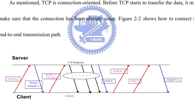
(17) the reliable delivery of data, it retransmits each segment if an ACK is not received in a certain period of time. TCP sets this timeout as a function of the RTT. After client receives the TCP packet, it will send back an Acknowledgement for signaling the server that the packet is already correct received. If the timer expires and server still does not receive the ACK, it will be thought that the packet is lost and the packet will be retransmitted.. 2.2.2 Three-Way Handshake. As mentioned, TCP is connection-oriented. Before TCP starts to transfer the data, it must make sure that the connection has been already setup. Figure 2-2 shows how to connect the end-to-end transmission path.. Figure 2-1 Three-way handshake and Four-way handshake. First, the client sends the SYN k to the server, which brings the start sequence number of next segment. After server receives the request, it will send a response for the message combining with the SYN J and ACK k+1. Finally, when client receives the message from the 10.
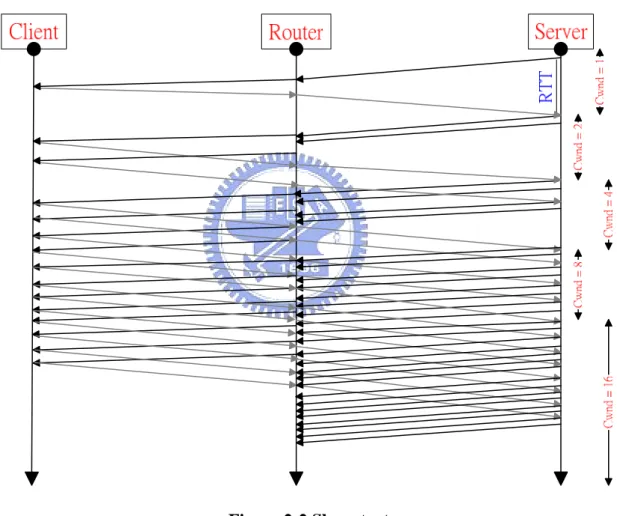
(18) server, it sends an ACK J+1 back. After that, the connection is setup successfully. This is called three-way handshake. Terminating the connection is similar with the initialization of connection. The difference is the two way connections are not closed simultaneously. Therefore, it needs to send four packets for it, which is called four-way handshake. All mentioned above are the TCP basic concepts. Next, we introduce the four TCP transmission algorithms. These algorithms are used to control the data transmission.. 2.2.3 TCP Transmission Algorithms. In TCP transmission, there are various controls that are related to each other. The controls are slow start with congestion avoidance and fast retransmission with fast recovery. When segments which stand for the packets by TCP are transferred, TCP uses the congestion window (cwnd) as the unit of transmission. In the network environment, the packets are transferred from the sender to the receiver continuously until the advertised window used by the receiver shows that there is not enough space for any packets. But the end-to-end users do not know how many capacity in network is available. In order to avoid the problem, the slow start algorithm is implemented. The slow start means that after the connection has established, the congestion window is initialized to one. After the first successful receiving segment, it will send back an ACK for the acknowledgement. Every time 11.
(19) when the sender receives one ACK, it sends two segments. In other words, the number of segment increases at the order of 2 n , for n=0, 1, 2, and etc. Figure 2-3 shows the implementation of the slow start. In this way the sender can probe the capacity which how many packets it can safely have in transit. Besides slow start can effectively increases the congestion window exponentially, rather than linearly.. Figure 2-2 Slow start. The congestion window increases until the slow start threshold (ssthresh) is reached. After that, TCP will go into the congestion avoidance state. Hence the slow start threshold is taken as an indication to tell sender change the form of the cwnd increase. Congestion. 12.
(20) avoidance means that the cwnd increases linearly. The equation (3) and (4) show that the cwnd increase form. Slow start. cwnd < ssthresh Cwnd[(n+1)-th] = 2 * cwnd[n-th]. Congestion avoidance. (3). cwnd >= ssthersh cwnd [(n+1)-th] = cwnd [n-th]. (4). Equation (3) is the slow start phase and the n-th, (n+1)-th means the round-trip number. In slow start phase, as mentioned, the cwnd increases at the order of 2 n for each round-trip. Equation (4) is the congestion avoidance phase, and the cwnd will increase one per round-trip. And in TCP, there is two indications of packet loss are timeout and duplicate ACKs. Because the wireline transmission is stable, the time between transmission of a segment and reception of ACK is called Round Trip Time (RTT). The RTT is one of important factors to calculate RTO (Retransmission timeout). When the timeout occurs, cwnd is down to one segment and ssthresh reduces by half to its current cwnd. Then the algorithm goes through the slow start procedure again. From the above algorithms, we can see that when timeout occurs, it will significant decrease TCP throughput. The ssthresh value changes when the round-trip timeout occurs. As the equation (5) shows. ssthresh[(n + 1) − th] =. cwnd[n − th] 2. when timeout occurs. (5). The fast retransmission and fast recovery is used by the receiver to signaling the packet. 13.
(21) out of order. Fast retransmission will be trigger when the sender received more the three the same acknowledgement sequence number. After that TCP server will reset the retransmission timeout timer and retransmits the packet immediately. The fast recovery algorithm will change the congestion window to half of original rather than one when the fast retransmission is successfully. But in the wireless transmission it might not proper. The transmission rate of wireline network is very high, hence the transmission delay is very short. After receive more than three ACK, the timer will not expire. But it is not the same for the wireless transmission, the lower transmission rate causes larger transmission delay, when server receives more than three ACK the timer is possible to exceed the RTO. So we do not consider these two algorithms in this problem.. 14.
(22) Chapter 3 Relation between TCP Performance and MAC scheduler. In 1xEV-DO system, a TCP packet will be composed by multiple MAC packets, and based on different scheduler algorithm, the system will decide when to schedule a MAC packet. As a result, different schedulers will have different impacts on TCP performance. In this chapter, we will investigate a well known MAC scheduler to discuss the relation between TCP performance and MAC scheduler.. 3.1.. Proportional Fairness MAC scheduler. Proportional Fairness (PF) MAC scheduler was been shown as an effective scheduler algorithm for MAC performance. The principal of the PF algorithm is to schedule a user who has the maximum ratio of Data Rate Control channel (DRC) to average transmission rate. The DRC is the requested channel rate based on RF condition. The transmission priority, S(n), is calculated as: S ( n ) = arg max i. DRC i ( n ) Ri ( n ). (6). ,. 15.
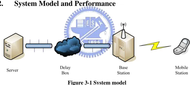
(23) where Ri ( n) = ( 1-. 1 T. ) R i (n-1 ) +. 1 T. assigned DRCi (n) and T is the average duration. In general, a scheduler algorithm decides the order of the channel assignment. By taking the benefit of channel variation among users, the PF algorithm intents to select the user with the highest ratio defined in Equation (6). In other words, the focus on the PF design is to maximize the throughput by choosing the maximum DRC request among users and the fairness is controlled by the average transmission rates.. 3.2.. System Model and Performance. Server. Delay Box. Base Station. Mobile Station. Figure 3-1 System model. System model is depicted in Figure 3-1 and our simulation platform is based on 1xEV-DO revision 0. For simplify, the base station and base station controller are combined in same node. Between server and base station, there is a node called DelayBox [20]. The DelayBox is a model developed in network simulator ns-2 and it can simulate the congestion behavior of the wireline network. The implement of DelayBox is a FIFO queue. If DelayBox reaches its maximum queue size, upcoming packets will be dropped. Also, if the head packet 16.
(24) of the queue wants to leave, it needs to wait for a period of time after previous packet finishing its transmission. By these two methods, DelayBox can act like wireline network with congestion and delay. In our simulation platform, all users’ packets and pseudo packets will be processed by the DelayBox. These pseudo packets are acting like other packets in wireline network and these pseudo packets are generated based on Poisson distribution. Other simulation parameters are as follows: For the simulation, each performance point is based on 40 runs and each run will last 80 seconds. For each run, there are 20 users in a sector and no user will neither enter nor leave system during 80 seconds. Besides, we take several fading channel to observe performance under different mobile conditions. These fading channels are AWGN, 1 path Rayleigh fading with 3Kmph, 30Kmph and 100Kmph, 2 path Rayleigh fading with 3Kmph, 30Kmph and 100Kmph. Also, the traffic model is FTP [21] for TCP performance study. For the DelayBox, we assume the maximum queue size is 600 TCP packets and packet leaving interval is based on exponential distribution with mean 0.05ms. In the downlink, despite DelayBox’s delay, it has a fix 100ms network delay. But in the reverse link, a fixed 200ms network delay is assumed, without DelayBox delay.. 17.
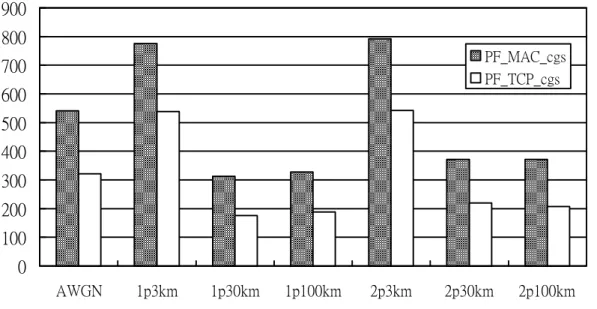
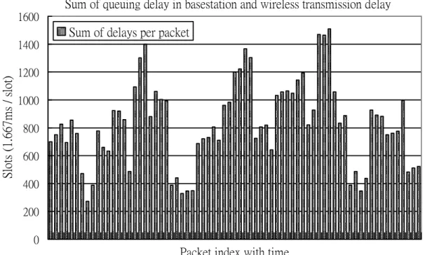
(25) FTP - 20 user - PF Scheduler - MAC and TCP performance (Kbps) 900 800 PF_MAC_cgs PF_TCP_cgs. 700 600 500 400 300 200 100 0 AWGN. 1p3km. 1p30km. 1p100km. 2p3km. 2p30km. 2p100km. Figure 3-2 System MAC and TCP performance with PF scheduler. Based on proportional fairness (PF) scheduler, Figure 3-2 is MAC and TCP performance in a sector with network congestion (cgs). In low mobility, channel estimation is more accurate than high mobility. As compared to AWGN, the PF scheduler can further improve the MAC performance at 3kmph for both 1path and 2path Rayleigh fading by taking the benefit from the channel diversity. For TCP performance, the practical performance is degraded significantly due to the TCP retransmission packets which are caused by timeouts. There are many reasons to cause timeouts in TCP layer. These reasons can be packet loss by congestion, wireless transmission error and too large congestion window. But with the consideration of scheduler, we observe another reason. Scheduler makes sum of each TCP packet’s wireless transmission delay and queuing delay in base station growing suddenly. This phenomenon may causes some unnecessary timeout and it can be seen in Figure 3-3. 18.
(26) Sum of queuing delay in basestation and wireless transmission delay 1600. Sum of delays per packet. Slots (1.667ms / slot). 1400 1200 1000 800 600 400 200 0. Packet index with time Figure 3-3 Sum of Queuing delay in base station and wireless transmission delay. To solve this problem, traditional MAC scheduler design is not sufficient to solve the above problem. It is the reason that traditional MAC scheduler only consider MAC layer performance and don’t know the interaction between MAC and TCP layer. Therefore, we propose a new MAC scheduler which takes TCP performance and interaction between MAC and TCP layer into consideration. This new scheduler called TCP Based Cross Layer Scheduler (TCLS) improves TCP performance by preventing unnecessary timeouts and will be introduced in next chapter.. 19.
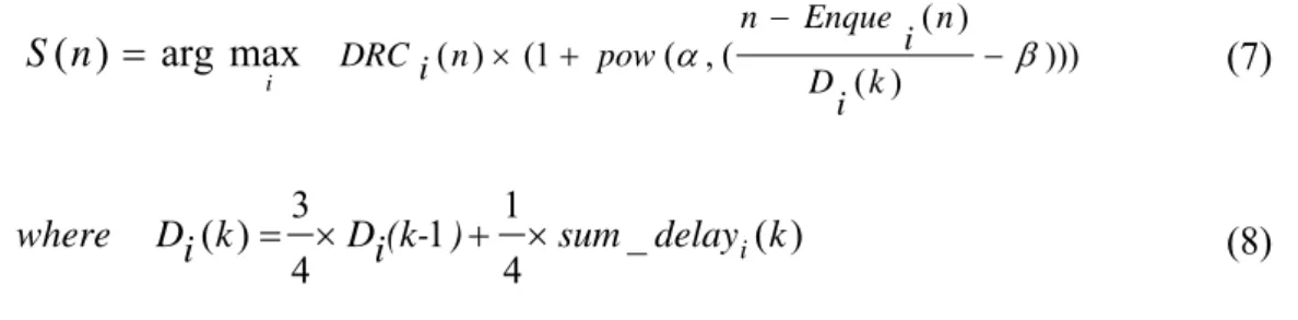
(27) Chapter 4 TCP Based Cross Layer Scheduler. In this Chapter, our proposed new MAC scheduler called TCP Based Cross Layer Scheduler (TCLS) will be introduced. Because it is just cross layer consideration, system architecture will be no different from original 1xEV-DO revision 0.. 4.1.. Background of proposed algorithm. For our proposed new MAC scheduler, MAC layer can know which MAC packets belong to a TCP packet. To implement our proposed algorithm, we need extra resources to record when each TCP packet enters the queue in base station. Also, by ACKs of MAC retransmission, sum of each TCP packet’s wireless transmission delay and queuing delay in base station is calculable.. 4.2.. Proposed algorithm. The main concept behind TCP Based Cross Layer Scheduler (TCLS) is to prevent sum of each TCP packet’s wireless transmission delay and queuing delay in base station from growing suddenly. TCLS calculates the priority user based on equation (7): 20.
(28) S ( n ) = arg max DRC i ( n ) × (1 + pow (α , ( i. where. n − Enque ( n ) i − β ))) D (k ) i. 3 1 Di ( k ) = × Di (k-1 ) + × sum _ delay i ( k ) 4 4. (7). (8). For user i and at nth slot, Enque (n) is the slot time when head packet enters the base station i. queue. α decides how sharp the priority weight grows and β decides when the priority weight begin to grow. For user i, sum _ delay i ( k ) is the sum of the kth TCP packet’s wireless transmission delay and queuing delay in base station. Equation (8) will be updated when every TCP packet is transmitted successfully.. Di (k ). is the moving average of. sum _ delay i ( k ) .. 6 5. Weight. 4 3 2 1 0 Di(k) 0.000 0.125 0.250 0.375 0.500 0.625 0.750 0.875 1.000. Figure 4-1 Example of priority weight. Assume α is 256 and β is 0.75, figure 4-1 is the example of priority weight of. 21.
(29) (1 + pow(α , (. n − Enque ( n) i − β ))) . Vertical axis is the priority weight and Horizontal axis is the D (k ) i. value of n − Enque ( n) normalized to Di (k ) . As we can see, priority weight begins to grow i from 0.75* Di (k ) . If α become bigger, priority weight will grow more sharply. Therefore, by our proposed TCP Focus Cross Layer Scheduler, the sum of wireless transmission delay and queuing delay in base station can be controlled and will not grow suddenly. This control prevents some unnecessary timeouts caused by scheduling delay.. 22.
(30) Chapter 5 Simulation Results. We will compare MAC and TCP performance of proportional fairness (PF) MAC scheduler and proposed TCP Based Cross Layer Scheduler (TCLS) in this chapter.. FTP 20 user MAC layer throughput (Kbps) 1000 900 800. PF_cgs. 700. TCLS_cgs. 600 500 400 300 200 100 0 AWGN. 1p3km. 1p30km. 1p100km. 2p3km. 2p30km. 2p100km. Figure 5-1 MAC layer throughput comparison. Table 5-1 MAC layer throughput improvement (%) cgs. AWGN. 1p3km. 1p30km. 1p100km. 2p3km. 2p30km. 2p100km. 71.4. 2.9. 81.44. 77.6. 13.6. 79.9. 85.1. Figure 5-1 is the MAC layer throughput comparison between PF and TCLS. First, we 23.
(31) can notice that MAC performance in 2 path Rayleigh fading is higher than 1 path by better RF condition. Furthermore, TCLS’s MAC layer throughputs are higher than PF in all fading channels. It is the reason that TCLS have DRC term in equation (7) and give good channel condition users higher priority. But look at Table 5-1, MAC layer throughput improvement is smaller in 3kmph of both 1path and 2 path Rayleigh fading. This can be explained by Table 5-2.. Table 5-2 Average success transmitted slots per 48000 slots (80 sec) simulation AWGN. 1p3km. 1p30km. 1p100km. 2p3km. 2p30km. 2p100km. PF. 19159. 38759. 16175. 16549. 33641. 16951. 16840. TCLS. 25109. 38399. 23350. 22216. 34327. 22990. 21995. Table 5-2 is the average success transmitted slots per 48000 slots (80 sec) simulation and MAC retransmission slot are not counted in it. Compared to PF, in AWGN and High mobility circumstance, TCLS saves the slots for MAC retransmission of bad channel condition users and give to good channel condition user. In low mobility circumstance, PF get benefit from better RF condition and channel diversity. Therefore, MAC throughput improvement in AWGN and High mobility circumstance is better than in low mobility circumstance.. 24.
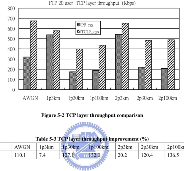
(32) FTP 20 user TCP layer throughput (Kbps) 800 700 PF_cgs. 600. TCLS_cgs. 500 400 300 200 100 0. AWGN. 1p3km. 1p30km. 1p100km. 2p3km. 2p30km. 2p100km. Figure 5-2 TCP layer throughput comparison. Table 5-3 TCP layer throughput improvement (%) cgs. AWGN. 1p3km. 1p30km. 1p100km. 2p3km. 2p30km. 2p100km. 110.1. 7.4. 127.1. 132.0. 20.2. 120.4. 136.5. Figure 5-2 is the TCP layer throughput comparison between PF and TCLS and Table 5-3 is the improvement percentage. As we can see, TCP throughput has degradation from MAC throughput in all fading channel and TCP layer throughput has the same trend of MAC layer throughput. However, different scheduler has different level of throughput degradation. Making comparison of Table 5-1 and Table 5-3, TCP throughput improvement is higher than MAC throughput improvement. This means TCLS makes lesser throughput degradation and prevents unnecessary timeouts caused by scheduling delay.. 25.
(33) Chapter 6 Conclusion. In this thesis, our contributions are 1) establishing an end-to-end simulation platform of 1xEV-DO system, 2) proposing a new MAC scheduler called TCP based Cross Layer Scheduler (TCLS) to enhance TCP performance. TCLS prevents the sum of each TCP packet’s wireless transmission delay and queuing delay in base station from growing suddenly. By this way, TCLS prevents unnecessary timeout caused by scheduling delay and reduce the number of TCP retransmission packets to improve TCP performance.. 26.
(34) List of References [1] A. Bakre, B.R. Badrinath, “I-TCP:Indirect TCP for Mobile Hosts,” in Proc. of the 15th International Conference on Distributed Computing Systems, Vancouver, BC, May 1995 [2] Raisinghani, V.T.; Singh, A.K.; Iyer, S.; “Improving TCP performance over mobile wireless environments using cross layer feedback”, Personal Wireless Communications, 2002 IEEE International Conference on 15-17 Dec. 2002 Page(s):81 - 85 [3] Yong Bai; Gang Wu; Ogielski, A.T.; “TCP/RLP coordination and interprotocol signaling for wireless Internet”, Vehicular Technology Conference, 1999 IEEE 49th Volume 3, 16-20 May 1999 Page(s):1945 - 1951 vol.3 [4] Kliazovich, D.; Graneill, F.; “A cross-layer scheme for TCP performance improvement in wireless LANs”, Global Telecommunications Conference, 2004. GLOBECOM '04. IEEE Volume 2, 29 Nov.-3 Dec. 2004 Page(s):840 - 844 Vol.2 [5] Klein, T.E.; Leung, K.K.; Haitao Zheng; “Improved TCP performance in wireless IP networks through enhanced opportunistic scheduling algorithms”, Global Telecommunications Conference, 2004. GLOBECOM '04. IEEE Volume 5, 29 Nov.-3 Dec. 2004 Page(s):2744 - 2748 Vol.5 [6] V. Jacobson, “Modified TCP Congestion Avoidance Algorithm”, mailing list, end2end-interest, 30 Apr. 1990. [7] http://www.3gpp2.com/ [8] ChingYao Huang; Qi Bi; Gandhi, A.; Brown, R.; Dongzhe Cui, “Forward and reverse link capacity for 1xEV-DO: third generation wireless high-speed data systems”, Global Telecommunications Conference, 2002. GLOBECOM '02. IEEE Volume 1, 17-21 Nov. 2002 Page(s):871 - 875 vol.1 [9] A. Jalali, R. Padovani and R. Pankaj, “Data throughput of CDMA-HDR a high efficiency-high data rate personal communication wireless system”, IEEE Vehicular Technology Conference, Tokyo, May 2000 [10] A. Yamaguchi, Y. Takeuchi, “Forward link packet scheduler for high-speed packet data system”, Personal, Indoor and Mobile Radio Communications, 2001 12th IEEE International Symposium on , Volume: 2 , Sep/Oct 2001, Page(s): F-21 -F-24 vol.2. [11] C.Y. Huang, H.Y. Su, S. Vitebsky, and P.C. Chen, “Schedulers for 1xEV-DO: Third Generation Wireless High-Speed Data Systems”, IEEE VTC Spring, 2003, JeChu, South Korea, April 2003 [12] Andrews. M, Kumaran. K, Ramanan. K, Stolyar. A, Whiting. P, Vijayakumar. R, “Providing quality of service over a shared wireless link”, IEEE Communications Magazine , Volume: 39 Issue: 2 , Feb 2001, Page(s): 150 -154 [13] S.Shakkotti and A. Stolyar, “A Study of Scheduling Algorithms for a Mixture of Realand Non-Real-Time Data in HDR”, Bell Labs Tech., Aug. 2000. [14] K. Chang; Y. Han, “QoS-based adaptive scheduling for a mixed service in HDR system”, 27.
(35) [15]. [16]. [17]. [18]. Personal, Indoor and Mobile Radio Communications, 2002. The 13th IEEE International Symposium on , Volume: 4 , 2002, Page(s): 1914 -1918 J. Kim, D. Lee, G. Hwang, C. Oh, “A new scheduling algorithm for data services in HDR system: weight-gap first scheduling”, Info-tech and Info-net, 2001. Proceedings. ICII 2001 - Beijing. 2001 International Conferences on , Volume: 2 , 2001, Page(s): 329 -334 vol.2 K. Kim, H. Kim, Y. Han, “A proportionally fair scheduling algorithm with QoS and priority in 1XEV-DO”, Personal, Indoor and Mobile Radio Communications, 2002. The 13th IEEE International Symposium on , Volume: 5 , 2002, Page(s): 2239 -2243. Y. Choi, Y. Han, “A channel-based scheduling algorithm for CDMA2000 1xEV-DO system”, Wireless Personal Multimedia Communications, 2002. The 5th International Symposium on , Volume: 2 , 2002, Page(s): 621 -625 Chapter 3.4 in 3GPP2 C.S0024-0 “cdma2000 High Rate Packet Data Air Interface Specification”. [19] Larry L. Peterson, Bruce S. Davie “Computer Networks”, Margan Kaufmann [20] DelayBox http://dirt.cs.unc.edu/delaybox/index.html [21] IST-2003-507581 WINNER D1.2 Intermediate requirements per scenario. 28.
(36)
數據
+5
相關文件
圖4 1 整合資訊系統風險 圖4.1 整合資訊系統風險..
a 全世界各種不同的網路所串連組合而成的網路系統,主要是 為了將這些網路能夠連結起來,然後透過國際間「傳輸通訊 控制協定」(Transmission
¾ To fetch a Web page, browser establishes TCP connection to the machine where the page is and sends a message over the connection asking for the
Each unit in hidden layer receives only a portion of total errors and these errors then feedback to the input layer.. Go to step 4 until the error is
This research focuses on the analysis of the characteristics of the Supreme Court verdicts on project schedule disputes in order to pinpoint the main reason for delay
Although various schedule delay analysis methodologies, professional project management software and commercial delay analysis software are available, delay analysts still
Developing a signal logic to protect pedestrian who is crossing an intersection is the first purpose of this study.. In addition, to improve the reliability and reduce delay of
Developing a signal logic to protect pedestrian who is crossing an intersection is the first purpose of this study.. In addition, to improve the reliability and reduce delay of
