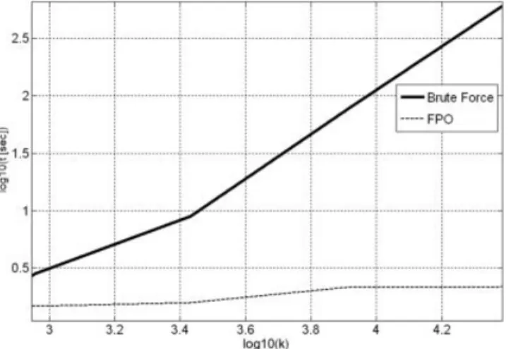
O(k) for each integral and a number of incident angles O(k) gives O(k2). With the FPO proposed, the computation time for all incident angles is nearly O(1).
5. Conclusions
A method for the efficient calculation of the whole radar cross-section pattern of infinite cylindrical shells with arbitrary cross section is presented. It has been shown that the computation time is independent of frequency. Accuracy is also good for all frequen-cies and incident angles.
ACKNOWLEDGMENTS
This work has been supported by the Spanish Ministerio de Edu-cacio´n y Ciencia under the project TEC2004-04866-C04-01. APPENDIX
The UGO used to compare the method presented in this article is as follows:
冕
x1 x2 f共 x兲exp共jkg共x兲兲dx ⫽ f共x1兲 jkg⬘共x1兲 ⫺ f共x2兲 jkg⬘共x2兲 ⫹ ⫹冑
kg2⬙共x 0兲 f共x0兲exp共ikg共x0兲兲, (A1)where the first two terms give the contribution of the endpoints, the third term gives the contribution of the reflection point.
REFERENCES
1. P.H. Pathak, Techniques for high frequency problems, In: Y.T. Lo and S.W. Lee (Eds.), Antenna handbook, theory, application and design, Van Nostrand Reinhold, New York, 1988.
2. L. Infante and M Stefano, Near-field line-integral representation of the Kirchhoff-type aperture radiation for parabolic reflector, IEEE Antenna Wireless Propag Lett 2 (2003), 273–276.
3. O.M. Conde, J. Pe´rez, and M.F. Ca´tedra, Stationary phase method application for the ana´lisis of radiation of complex 3-D conducting structures, IEEE Trans Antenna Propag 49 (2001), 724 –731. 4. P.F. Ca´tedra, Application of physical optics to the RCS computation of
bodies modeled with nurbs surfaces, IEEE Trans Antenna Propag 42 (1994), 1404 –1411.
5. A. Boag, A fast physical optics (FPO) algorithm for high frequency scattering, IEEE Trans Antenna Propag 52 (2004), 197–204. 6. A. Boag and E. Michielssen, A fast physical optics (FPO) algorithm for
double-bounce scattering, IEEE Trans Antenna Propag 52 (2004), 205– 212.
7. F.V. Bondı´a, M.F. Bataller, A. Valero-Nogueira, and E.A. Alos, A fast physical optics method for planar scatters with arbitrary contour, Mi-crowave Opt Technol Lett 49 (2007), 10.
8. D. Bouche, F. Molinet, and R. Mittra (Eds.), Asymptotic methods in electromagnetics, McGraw-Hill, Springer, 1997, pp. 416 – 431. 9. O.P. Bruno, Y. Han, and M.M. Pohlman, Accurate, high-order
repre-sentation of complex three-dimensional surfaces via Fourier-Continua-tion analysis, J Comput Phys, in press.
© 2008 Wiley Periodicals, Inc.
A CIRCULAR CPW-FED SLOT
ANTENNA RESONATED BY THE
CIRCULAR LOOP FOR BROADBAND
CIRCULARLY POLARIZED RADIATION
I-Chung Deng,1Qing-Xiang Ke,1Ren-Jie Lin,2and
Yueh-Tsu King3
1Department of Electronics Engineering, Institute of Mechatronic Engineering, Technology and Science Institute of Northern Taiwan, Taipei, Taiwan 112, Republic of China
2Department of Electronics Engineering, Institute of Electronics, National Chiao Tung University, Hsinchu, Taiwan 30050, Republic of China
3Animal Technology Institute Taiwan, Miaoli, Taiwan 350, Republic of China; Corresponding author: [email protected]
Received 4 October 2007
ABSTRACT: The coplanar waveguide (CPW) fed circular slot antenna,
resonated by the circular loop with a narrow opening, is designed for obtaining broadband circularly polarized (CP) radiation. The length of protruded signal strip (LS) is utilized to adjust the phase difference
be-tween two orthogonal field components in the circularly polarized waves. In this design, the proposed antenna has the minimum return loss of⫺56.5 dB at the frequency of 2.403 GHz. The impedance and 3 dB axial-ratio bandwidths can reach up to 740 MHz or 33.3% and 390 MHz or 16.6%, respectively. In addition, the simulated results are about as good as those of the measured ones. © 2008 Wiley Periodicals, Inc.
Microwave Opt Technol Lett 50: 1423–1426, 2008; Published online in Wiley InterScience (www.interscience.wiley.com). DOI 10.1002/mop. 23359
Key words: circular polarization; CPW-fed; circular loop
1. INTRODUCTION
The microstrip-fed antennas suffer from the need for careful align-ment of the etchings on the two sides of the PC board. Also, the use of a microstrip line is not compatible with the monolithic microwave integrated circuits (MMIC) fabrication and, therefore, an easier integration with device is not possible [1, 2]. Further-more, when the same substrate is used, the slot antennas usually have a much wider circular polarization (CP) bandwidth than the conventional single-fed CP microstrip antenna the CP bandwidth of which is usually less than 2% [1]. Coplanar waveguide (CPW) fed printed slot antennas have not only relatively much wider impedance bandwidth than the design with a microstrip line fed, but also easily integrated with integrated circuits by using a single metallic layer [3]. The designs of the CPW-fed slot antennas have recently motivated the present study.
Figure 8 Computation time of the whole radiation pattern. Brute force versus FPO
This article presents a simple design of a CPW-fed circular slot antenna with broadband CP radiation. To generate a CP wave, the circular loop is slit into two arms. The CP wave is radiated when two standing-wave current distributions are of equal amplitude and quarter-wave length difference [4, 5]. The length of the two arms is used to adjust two standing-wave current. A protruded strip connects the CPW feed line and the circular loop to resonate a frequency of 2.45 GHz. Furthermore, by adjusting the length of the protruded strip and the circumference of the circular loop, a good impedance matching and excellent characteristics of axial ratio (AR) can be achieved.
Both the return loss and the radiation patterns are given in this article.
2. ANTENNA STRUCTURE
The antenna geometry is shown in Figure 1. This antenna is realized on an inexpensive FR4 dielectric substrate with a thick-ness of 1.6 mm (h) and a relative permittivity of 4.4 (r). In these suggested antennas, a 50-⍀ coplanar waveguide with a protruded signal strip (length⫽ LS) is used to feed the antenna. The width of signal feed line (Wf) is 6.37 mm with a gap g1⫽ 0.5 mm, which is between the signal feed line and the ground plane. From the empirical experiences, the circumference of the circular loop is about 1.125 eff (eff is the wavelength of the operational fre-quency in FR4 substrate). To radiate an axial ratio (AR) wave, a small gap g2⫽ 1.4 mm is inserted into the circular loop (radius is Rin) and two arms are thus formed. Moreover, the long arm of the circular loop is about 1effand the short one is about 0.125eff. Both widths of the protruded strip and the circular loop are fixed to be 1 mm. Furthermore, the radius of Routis fixed to 19 mm, and the width of circular ground (W1) is chosen to be 9 mm. Although the ground size has less influence on the characteristics of the antenna, the asymmetrical ground is still used for improving the 3
dB AR bandwidth and the AR space distribution [6, 7]. The widths of W3and W4are fixed to be 16 and 13 mm, respectively. 3. EXPERIMENTAL RESULTS AND DISCUSSION
The effects of the length of the protruded signal strip (LS) of the proposed antenna on the impedance matching and the AR value have been investigated. By varying the lengths of LS, the widest impedance bandwidth of 556 MHz (from 1.987 GHz to 2.543 GHz) has been achieved. Figure 2 shows the simulated return ratio against the frequency of the proposed antenna with different signal strip lengths (LS) of 8.5, 9.5, and 10.5 mm. It is apparent that as the length of LS increases, the center frequency of the return ratio shifts toward the lower frequency. When the signal strip length of LSis 9.5 mm, the resonant frequency of 2.4 GHz and the minimum return ratio of ⫺62 dB are obtained. Moreover, the measured return loss (S11) of the proposed antenna (LS⫽ 9.5 mm), with a minimum return ratio of⫺56.5 dB at the resonant frequency of 2.4 GHz, is also shown in Figure 2. Both results of the simulation and the measurement show good agreement.
R
outR
inW
1g2
W
2W
3W
fW
4 g1L
s hε
r50 ohm coplanar waveguide
Figure 1 Geometry of the circular CPW-fed slot antenna resonated by the circular loop
1.0 1.2 1.4 1.6 1.8 2.0 2.2 2.4 2.6 2.8 3.0 -70 -60 -50 -40 -30 -20 -10 0 R e tur n los s (d B ) Frequency (GHz) Ls(mm) 8.5 9.5 10.5 Measurement 2.403GHz 1.85GHz 2.59GHz
Figure 2 Simulated and measured return loss of proposed antenna dur-ing the various frequencies for different signal strip lengths of 8.5, 9.5, and 10.5 mm 1.9 2.0 2.1 2.2 2.3 2.4 2.5 2.6 2.7 2.8 2.9 3.0 0 3 6 9 12 15 18 21 2.52GHz AR (d B ) Frequency (GHz) Ls (mm) 8.5 9.5 10.5 2.17GHz
Figure 3 Simulated axial ratios of proposed antenna during the various frequencies for different signal strip lengths of 8.5, 9.5, and 10.5 mm
To achieve a CP wave, the circular loop is slit into two arms and thus it generated two orthogonal field components with an equal amplitude but in phase quadrature. The radius of the circular loop (Rin), the position of the gap between the two arms, and the size of the gap (g2) can be used to tune the amplitude and the phase of two orthogonal field components. The Rinis determined by the length of the protruded strip LSbecause the circular loop must be kept in the center of the circular slot. Therefore, the major key parameter, which influences the CP operation, is LSand g2. To simplify the design, from our experiences, the position of the gap, with a fixed size of 1.4 mm on the circular loop, is chosen to be located at about 45 degree referring to the protruded signal strip. A quite wide AR bandwidth may be obtained by properly adjusting the length of LS. Figure 3 shows the simulated AR value of the proposed antenna during various frequencies. Although the pro-posed antenna can achieve wider bandwidth when the length of LS is 10.5 mm, we still choose 9.5 mm as the length of LSto gain the lowest AR value at 2.4 GHz (same as the resonant frequency).
Figure 4(a) shows the simulated AR value of the proposed antenna against the elevation angle () at the azimuthal angles of ⫽ 0° and 90°, with the frequency set at 2.4 GHz. When the elevation angles range from⫺50° to 40° at ⫽ 0° (square line), the AR value is lower than 3 dB. Correspondingly, as is at 90° (circle line) and ranges from ⫺40° to 50°, we found that the AR value is less than 3 dB. Therefore, we conclude that the proposed antenna demonstrates a good CP characteristic in space distribu-tion. Figure 4(b) reveals the measured AR value of the proposed antenna against the elevation angle () at 2.4 GHz. Moreover, the radiation pattern of the proposed antenna is measured and its AR values are lower than 3 dB, whereas the elevated angles range from ⫺46° to 36° at ⫹z direction, and a mirror pattern is measured at ⫺z direction. Comparing with the measured result in Figure 4(a) at ⫽ 0 degree, the simulation one in Figure 4(b) shows very good agreement and the small difference can be thus explained from the fabricated tolerance, the measurement error, and the environmental interference.
The AR value and the antenna gain are measured and are simulated at different frequencies as shown in Figure 5. Figure 5(a) shows that the CP bandwidth, determined by 3 dB AR, is about
-180 -150 -120 -90 -60 -30 0 30 60 90 120 150 180 0 3 6 9 12 15 18 21 Ax ia l rati o (d B ) Frequency (GHz) phi=0 phi=90 (a) -30 -27 -24 -21 -18 -15 -12 -9 -6 -3 0 3 0 30 60 90 120 150 180 210 240 270 300 330 -30 -27 -24 -21 -18 -15 -12 -9 -6 -3 0 3 2.4GHz (b)
Figure 4 (a) Simulated axial ratio against elevation angle () with different azimuthal angels of ⫽ 0 and 90 degrees at 2.45 GHz. (b) Measured polarization patterns with different azimuthal angels of ⫽ 0 at 2.45 GHz 1.9 2.0 2.1 2.2 2.3 2.4 2.5 2.6 2.7 2.8 2.9 3.0 0 3 6 9 12 15 18 21 2.15GHz AR (dB ) Frequency (GHz) Simulation Measurement 2.54GHz (a) 1.9 2.0 2.1 2.2 2.3 2.4 2.5 2.6 2.0 2.2 2.4 2.6 2.8 3.0 3.2 3.4 3.6 3.8 4.0 Ga in (d B i) Frequency (GHz) Simulation Measurement (b)
Figure 5 Simulated and measured (a) axial ratios and (b) antenna gain for proposed during the various frequencies
370 MHz or 15.8% (from 2.15 GHz to 2.52 GHz) and 390 MHz or 16.6% (from 2.15 GHz to 2.54 GHz), respectively, for simulated and measured results. The variations of the antenna gain are only 0.2 dBi from 2.1 GHz to 2.4 GHz, and the maximum antenna gain is 3.8 dBi at 2.15 GHz. Figure 6 shows the simulated radiation patterns in two orthogonal planes at 2.4 GHz. Therefore, this figure clearly reveals that our proposed antenna radiates a good LHCP wave in wide elevation angles, including the directions of⫹z and ⫺z.
4. CONCLUSION
A single layer circularly polarized CPW-fed circular slot antenna has been successfully demonstrated. Even fabricated on the inex-pensive FR4 substrate, this antenna still reveals excellent perfor-mance at 2.4 GHz. To sum up, by properly adjusting the length of the protruded signal strip, the proposed antenna can be designed to have an impedance bandwidth of 740 MHz (33.3%) and a 3 dB AR bandwidth of 390 MHz (16.6%), good broadside LHCP radiation patterns over a wide elevation angle range, and the maximum antenna gain of 3.8. To conclude, our proposed antenna could provide good CP radiation for wide bandwidth transmitting and receiving applications.
ACKNOWLEDGMENTS
This project is supported by the National Science Council under grant NSC 94-3111-466-003-Y21.
REFERENCES
1. K.C. Gupta, R. Garg, and I. J. Bahl, Microstrip lines and solt lines, 2nd ed. Artech House, Norwood, MA, 1996.
2. W. Menzel and W. Grabherr, A microstrip patch antenna with coplanar feed line, IEEE Microwave Guided Wave Lett 1 (1991), 340 –342. 3. T.J. Ellis, J.P. Raskin, G.M. Rebeiz, and L.P.B. Katehi, A Wideband
CPW-fed microstrip antenna at millimeter-wave frequencies, In Proc IEEE MMT-S Interantional Microwave Symposium Digest, vol. 2, Anaheim, CA, June 1999, pp. 629 – 632.
4. R.L. Li, N.A. Bushyager, J. Laskar, and M.M. Tentzeris, Determination of reactance loading for circularly polarized circular loop antennas with a uniform traveling-wave current distribution, IEEE Trans Antennas Propag 53 (2005), 3920 –3929.
5. R.S. Elliott, Antenna theory and design, IEEE Press, Piscataway, NJ, 2003, pp. 71–73.
6. K.M. Chang, R.J. Lin, I.C. Deng, J.B. Chen, Q.X. Ke, J.R. Chang, A Novel design of a CPW-fed square slot antenna with broadband circular polarization, Microwave Opt Technol Lett 48 (2006), 2456 –2459. 7. I.C. Deng, J.B. Chen, Q.X. Ke, J.R. Chang, W.F. Chang, and Y.T. King,
A circular CPW-fed slot antenna for broadband circularly polarized radiation, Microwave Opt Technol Lett, in press
© 2008 Wiley Periodicals, Inc.
BANDPASS FILTER WITH IMPROVED
SPURIOUS PERFORMANCE USING
MODIFIED RING DIELECTRIC
RESONATOR IN MIC ENVIRONMENT
Kumar Vaibhav Srivastava, Vishwa V. Mishra, and Animesh Biswas
Department of Electrical Engineering, Indian Institute of Technology, Kanpur, Uttar Pradesh, India; Corresponding author:
Received 4 October 2007
ABSTRACT: A C-band bandpass filter is designed using modified ring
dielectric resonator in microwave integrated circuit (MIC) environment for improved spurious response. The dielectric resonator (DR) filters are generally made in cavity environment because of its good spurious re-sponse in cavity environment, but its spurious performance degrades as the filter is designed in MIC environment. In MIC environment, the smaller substrate thickness makes DR closer to ground plane and affects its resonance mode spectrum which, in turn, affects closely spaced reso-nant frequencies. The dense resoreso-nant mode spectrum of DR in MIC en-vironment limits its application for filter designing. This article intro-duces a comparative study on filter realization with modified ring DR and conventional ring DR to show the improvement of spurious re-sponse in MIC environment. The simulated and measured results of these filters are presented to demonstrate the validity of the design procedure and improvement of spurious response. © 2008 Wiley Periodicals, Inc.
Microwave Opt Technol Lett 50: 1426 –1431, 2008; Published online in Wiley InterScience (www.interscience.wiley.com). DOI 10.1002/mop. 23391
Key words: dielectric resonator (DR); dielectric resonator filter;
modi-fied ring dielectric resonator; spurious response; resonator mode sepa-ration
1. INTRODUCTION
The role of dielectric resonator (DR) in miniaturization of wave filter and oscillators is well recognized [1, 2]. The micro-wave filters consist of dielectric resonators that have good in-band performance, but the crowded mode spectrum of dielectric reso-nator gives poor out-of-band response. To get good out-of-band response, mode suppressor [3], and irises [4] have been suggested earlier to filter out the spurious modes. Further, the air-filled cylindrical cavities at the input [5], application of TM01␦mode for bandpass filter [6], mixed mode filter design [7], combine filter [8], and sandwiched conductors DR [9] are the well recognized ap-proaches for improving the spurious performance of dielectric resonator filters. But in all these filters, the attentions are mostly paid to cavity filters, where the dielectric resonators are placed within rectangular or cylindrical metal enclosures (cavity), and it has been found that very limited studies are available on dielectric resonator filters in microwave integrated circuit (MIC) environ-ment [10, 11]. The reason for using the DR in cavity environenviron-ment is that when DR is placed at the center of cavity, maximum mode separation can be achieved [12], whereas in MIC environment, the
-30 -27 -24 -21 -18 -15 -12 -9 -6 -3 0 3 0 30 60 90 120 150 180 210 240 270 300 330 -30 -27 -24 -21 -18 -15 -12 -9 -6 -3 0 3 Left phi_0 Left phi_90 Right phi_0 Right phi_90
Figure 6 Radiation patterns of the proposed antenna on the elevation plane at the resonant frequency of 2.4 GHz