Development of Rewritable Dual-layer Phase-change Optical Disks
Feng-Hsu Wu, Tsung-Eong Hsieh', Han-Ping D. Shieh
Institute of Electro-Optical Engineering,
'Department of materials Science and Engineering,
National Chiao Tung Univ., Hsin-Chu, Taiwan, 300
E-mail: [email protected]
Abstract
Dual-layer optical disks comprised of two data layers were developed to study readout/write/erase
characteristics. This disk was composed of recording layer land 2, of high transmittance and high
reflectivity, respectively. Layer 1 and 2 of 15 and 20 nm increase transmittance and reduce writing powerfor recording. Only 1.5 mW laser power was sufficient for readout, 9 and 16 mW was required for
recording on recording layer I and 2, respectively. Thse dual-layer disk can double data capacity on a disk substrate.
1. Introduction
Digital versatile disks (DVD) are now emerging in the market. Many advanced recording
technologies, such as mark-edge recording and landlgroove recording, have already been proposed for
DVD-RAM disks in increasing their recording density and capacity. Volumetric optical disks can increase the storage capacity by using multiple data layers for storage where the data are recorded on each layer of a
multi-layer stack"2, respectively. In this paper, we present the study of write/erase/read performance of a
dual-layer erasable optical disks using phase change recording media.
2. Design of disk structure and thermal simulation
The dual-layer optical disk was composed of two polycarbonate substrates3, which were coated with layer 1 and layer 2, as shown in Fig. 1, respectively. Layer 1 is the first data layer impinged by laser beam while layer 2 is the second layer. The data layers of the disk were spaced from each other by an UV resin
layer of4O jim in thickness.
The transmittance of the layer 1 must be sufficiently large in order to focus, track and record on the layer 2 through the layer 1 .Thus,the disk structure with no metallic reflective for the layer 1, which is in a "High-to-Low" structure, where the reflectivity decreases in accordance with recording process (crystalline
to amorphous state). Since metallic cooling layer accelerates phase change material in temperature
descending during recording process, recording performance of layer 1 of no metallic cooling layer will be lower.
For the layer 2, reflectivity must be high, because the incident laser beam is inevitably reduced by the light absorption and reflection from the layer 1 .
In
order to increase the optical efficiency, thetransmittance is set to zero. Thus, a "Low-to-High" structure is adopted. Besides, owing to write power of
laser pulse is proportional to thickness of recording media, proper thickness of recording media is
necessary. Therefore, schemes to meet the write power limit of commercial disk drive (less than 20 mW) by using thin active layer are necessary.By thin-film theorem and metric optics, the reflectivity, transitivity, and absorption coefficient of the two recording layers were calculated. A very simple 3 and 4 layers disk structure for recording layer 1 and
2 that meets the condition mentioned above was selected. Optical design of reflection, absorption and
optical head
substrate
ZnS-Si02
9mm ZnS-Si02 8mm UV resin layer ZnS-Si02 83nm ZnS-Si02 67nm Al-Cr 4Onm substrate} recording layer 1
} recording layer 2
Fic I Schematics of aduallayer opticaldiskstructure
crystalline state
21% 49%
amorphous
state
0 - ____________________37/0
recording
layer 1crystalline state
35%
65%
state
recording layer 2
reflection absorption transmittance
Fi 2 Reflection,absorption and transmittance ol layer I and 2 of a dual-layer optical disk
A gaussian—distributed diffraction limited spot impinged perpendicular on a disk of a multi—layered
thin film structure was then analyzed by thermal simulation. When the light penetrates the multi-layer
structure, its enertzy is absorbed by the recording layer. and converted into heat. '['he heat diltuses to
neighbor area and the other layers. The temperature distributions was calculated by a thermal simulation program "Temprofile"4 to ensure that quench rate was high enough for writing by simulation. 'l'he quench
rate of layer 1 and 2 is 6 and 9 Cins. respectively, as shown in Figs. 3, which can meet the writing
requIrements. th1 JJ Isi .4
3f11E
'
" Iyr 1
-' I?r2
U S sir sic 2ir 25 )5 SO
3. Experiment
Disks of recording layers 1 and 2, were deposited on a u-grooved 1 20-ram diameter polaycarbonate substrate separately, then glued together by an ultraviolet-light-cured resin. The parameters of the read and
write measurement are listed in Table 1. Write pulse patterns shown in Fig. 4 were frequency-modulated
between 3and9 MHz; peak laser power was modulated between 0 and 20 mW.
3MHz
6MHz 9MHz
I mir nrJ
!::::
time
Fig.4 Write pulse waveform used in this experiment
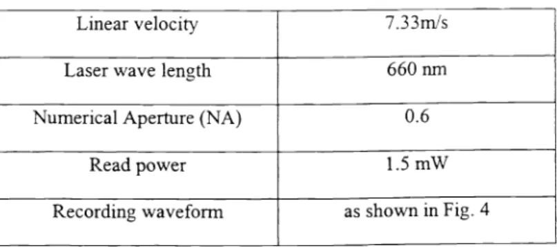
Table I Read/write parameters
Linear velocity 7.33m1s
Laser wave length 660 nm
Numerical Aperture (NA) 0.6
Read power 1.5 mW
Recording waveform as shown in Fig. 4
4. Results and discussions
CNR as a function of laser peak power for layer 1 and 2 was shown in Fig. 5. At writing frequency of 3 MHz, corresponding to 1.2 im in mark length, the peak power giving a CNR of 45dBwas 9 mW for layer 1 and 13 mW for the layer 2. The eraseability better than 35 dB was obtained at erase laser power of 6 and 9 mW for layer 1 and 2, respectively.
49 48 47
46
45
z
U44 43 42 41 4 6 8 10 12 14 writepower (mW)Fig. 5 CNR as a function of write power for layer I and 2 at recording frequency of 3 MHz
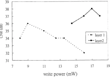
CNRasa function of laser peak power for layer 1 and 2 is shown in Fig. 6. The peak CNR is at power of 9 mW for layer 1 and at 13 mW for the layer 2 at recording frequency of 7 MHz, corresponding to
0.52 im in mark length. Thin recording layers were adopted in dual-layer optical disk recording in, to increase write power sensitivity, i.e. too low a write power won't be adequate for phase change media and too high write power will destroy the phase change material or disk track. Therefore, optimized write
power can achieve higher CNR on this dual-layer disk.
39 38 37
36
35
z
U 33 32 31 7 9 11 13 15 17 19 write power (mW)Fig. 6 CNR as a function of write power for layer I and 2 at recording frequency of 7 MHz
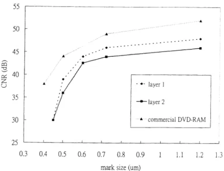
CNR as a function of mark size of layers 1 and 2 and a commercial I)VD-RAM disk is shown in Fig 7. CNRatmark size of 0.6 p.m higher than 43 dB is obtained on both layers. CNR of the dual-layer disks is very close to that of single layer DVD-RAM disks.
.
16 18 20 22.,...
layerl ......
layer2
..A
A
mark size (urn)
Fig. 7 CNR as a function of mark size of layers 1 ,layer2, and a commercial DVD-RAM disk
To examine the effect of layer 1 on the writing performance of layer 2, a single layer disk, "a
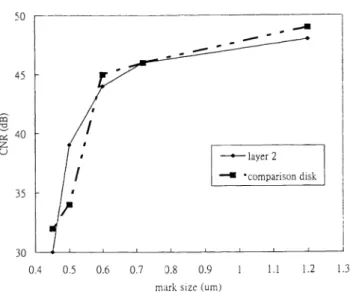
comparison disk" with the same disk structure as layer 2, was prepared. CNR as a function of write power for comparison disk and layer 2 was shown in Fig. 8. The peak CNR is at power of 8 mW for comparison disk and at 15 mW for the layer 2 of dual-layer disk at recording frequency of 3 MHz, implying that writing power is about double to compensate the optical energy lose in transmitting through the layer. Dependence of the CNR on the mark size for comparison disk and layer 2 of dual-layer disk as shown in Fig. 9. where
CNR write power of 10 and 16 mW are almost the same. According to the simulation, transmittance of
layer 1 approximate 60%, which agrees with peak power requirement (10 and 16 mW) measured
experimentally. 47 464
44 40 39 6 8 10 12 14 16 18 20 22 write power (mW)Fig. 8 CNR as a function of write power for comparison disk and layer 2
55 50 45 -c
40
z
C) 35 30 25 0.3 0.4 0.5 0.6 0.7 0.8 0.9 1ii
1.2 1.3 41 comparison disk • layer 245 40
z
U 35 0.4 0.5 0.6 0.7 0.8 0.9 1 1.1 1.2 1.3mark size (urn)
Fig. 9 CNR as a function ofthe mark size for comparison disk and the layer 2 ofdual-layer disk
5. Conclusion
The thermal and optical simulations facilitate the design of dual-layer erasable optical disks using
phase change recording media with high transmittance and high reflectivity recording layers, respectively.
CNR of 0.6 tm mark size on both layers was better than 45 dB at read power of 1 .5 mW. The results
suggest that dual-layer disks can be promising for double data capacity on a disk substrate.
Acknowledgement
This work was supported by National Science Council of the Republic of China under contract no.
NSC 88-2622-L-009-008.
Reference
1 Bor-Wen Yang, Han-Ping D Shieh, "Interlayer cross talk indual-layerread-only optical disks ",Applied
Optics, 38, 333 (1999)
2 Bor-Wen Yang, Han-Ping D Shieh, "The characteristics ofa dual-layer optical disk with read-only and erasablefunctions ",IEEEJournal ofSelected Topics in Quantum Electronics, 4, 821 (1998)
3 Kenichi Nagata, Noboru Yamada, Kenichi Nishiuchi, Shigeaki Furukawa and Nobuo Akahira, "Rewritable dual-layer phase change optical disk", Jpn. J. Appi. Phys. Vol. 3 8(1998) pp. 1679-1686
4 Temprofile, MM research, Inc.