172 IEEE PHOTONICS TECHNOLOGY LETTERS, VOL. 18, NO. 1, JANUARY 1, 2006
210-km Bidirectional Transmission System With
a Novel Four-Port Interleaver to Facilitate
Unidirectional Amplification
Ming-Fang Huang, Jason (Jyehong) Chen, Kai-Ming Feng, Chia-Chien Wei, Chung-Yu Lai, Tse-Yu Lin, and Sien Chi
Abstract—A novel bidirectional transmission system is proposed and experimentally demonstrated using a four-port interleaver to enable unidirectional amplification. Following bidirectional trans-mission through 210 km of standard single-mode fibers, sensitivity variations of less than 0.2 dB, with a bit-error rate level of 10 9at 10 Gb/s, were observed between bidirectional and unidirectional transmissions.
Index Terms—Bidirectional add/drop amplifier, interleaver, optical fiber communication, optical fiber device.
I. INTRODUCTION
I
N METRO area networks (MAN) that encounter fiber short-ages problems, bidirectional transmission is an appealing means of increasing the bandwidth utilization in a single-optical fiber and, at the same time, reducing the operation and mainte-nance cost [1]–[3]. One of the main difficulties associated with a bidirectional transmission system is realizing bidirectional am-plification, which typically requires high gain, low noise, and the elimination of Rayleigh backscattering (RB) [2]. Possible approaches for bidirectional amplification are band splitting or channel interleaving [1], [3], the use of arrayed waveguide grat-ings, Mach–Zehnder wavelength-division multiplexing (WDM) coupling, the use of circulators, or the use of a gain-clamping semiconductor optical amplifier, called a linear optical amplifier (LOA) [4]. However, these approaches require the use of two or more erbium-doped fiber amplifiers (EDFAs) to achieve bidi-rectional transmission. In the first scheme [3], a pair of WDMs or circulators are used to reroute the east and west traffics sep-arately; each traffic is then individually amplified using a cor-responding EDFA. The gains of EDFAs are typically limited to prevent RB-induced self-oscillation. In the LOA scheme [4], the characteristics of the gain-clamping effect limit the gain of LOA to under 20 dB and a high noise figure (NF) is inevitable. These shortcomings significantly reduce the distance of amplification span and the optical signal-to-noise ratio (OSNR) [5], increasing the operation cost and the degradation in the quality of trans-mission. This letter proposes and experimentally demonstrates aManuscript received August 4, 2005; revised October 9, 2005. This work was supported by the National Science Council, R.O.C., Taiwan, under Contracts NSC 94-2215-E-009-006, NSC 94-2215-E-155-001, NSC 94-2215-E-155-003, NSC 94-2219-E-007-008, and NSC 94-2752-E-007-002-PAE.
M.-F. Huang, J. J. Chen, C.-C. Wei, C.-Y. Lai, T.-Y. Lin, and S. Chi are with the Institute of Electro-Optical Engineering and Department of Photonics, Na-tional Chiao-Tung University, Taiwan, R.O.C.
K.-M. Feng is with the Institute of Communication Engineering, National Tsing Hua University, Taiwan, R.O.C. (e-mail: [email protected]).
Digital Object Identifier 10.1109/LPT.2005.861625
new four-port interleaver that enables bidirectional transmission using only unidirectional amplification. The primary function of this four-port interleaver is to redirect the bidirectional east and west traffic into unidirectional transmission in a single-ampli-fication section. The copropagating amplifier architecture was used because high-performance EDFAs are fundamentally uni-directional devices, optimized for a low noise figure and high output power with internal isolators for stable operation. To achieve this goal, in each transmission direction, optical WDM channels were set with 100-GHz spacing and the oppositely transmitted channels were then interleaved into 50-GHz spacing by the interleaver when bidirectional traffic was rerouted into the copropagating EDFA. After transmission for 210 km, sensi-tivity variations of under 0.2 dB, at 10 Gb/s with a bit-error rate (BER) level of 10 , were observed between bidirectional and unidirectional transmissions.
II. DEVICECHARACTERISTICS
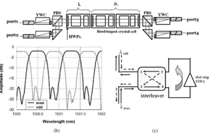
Birefringent crystal has for a long time been used in de-signing optical filters; such filters comprise birefringent crystal plates and polarizers. The two basic types of birefringent filters are Lyot–Öhman [6], [7] filters and Solc [8] filters. Both are based on interference between polarized light, which depends on phase retardation between the components of light polar-ized in parallel to the slow and the fast axes of the crystal. Consequently, birefringent crystal is used as an optical delay line, and a half-wave plate is used to alter the polarization between the delay stages. An optical filter can thus be made by cascading delay lines and controlling the angle of rotation be-tween half-wave plates. The interleaver designed and fabricated herein is a symmetrical four-port interleaver with two input and two output ports. Fig. 1(a) presents the configuration of the interleaver. It incorporates birefringent crystal cells, half-wave plates (HWP), YVO walk-off crystal (YWC), and polarization beam splitters (PBS). At the input and outputs of interleaver, YWC and an HWP were used to ensure that light that passed through optical delay cells, including two birefringent crystals, was polarized in only one direction. Each delay cell includes two birefringent crystals, namely YVO and rutile (TiO ), to compensate for any change in temperature. The detailed operating principles, architectures, and design rules associated with this interleaver are presented in [9]–[11]. Fig. 1(b) plots the measured amplitude response of the interleaver in even and odd channels. The channel spacing of this interleaver is 50 GHz with an insertion loss of 2.2 dB and a 0.5-dB passband of around
HUANG et al.: 210-km BIDIRECTIONAL TRANSMISSION SYSTEM WITH NOVEL FOUR-PORT INTERLEAVER 173
Fig. 1. (a) Detail configuration of four-port L-2L interleaver. (b) Transmission spectrum of interleaver for even and odd channels. (c) Routing mechanism of interleaver to transform bidirectional transmission to unidirectional transmission.
Fig. 2. Experimental setup of bidirectional transmission system.
35 GHz. The interleaver is designed to have complementary wavelength-dependent routing characteristics for even and odd channels by using the characteristic of amplitude response. For example, if (odd channel) enters port 1, then it will be routed to port 4. If (even channel) goes to port 2, then it will also be directed to port 4. This interleaver property is exploited to route to port 4 both east-even channels, arriving at port 2 of the interleaver, and west-odd channels, entering the interleaver at port 1. Therefore, a bidirectional transmission of even and odd channels can be transformed into a copropagating transmis-sion in a single-amplification section achieving unidirectional amplification using a single EDFA, as shown in Fig. 1(c).
III. EXPERIMENT ONBIDIRECTIONALTRANSMISSIONSYSTEM
A new wavelength-sensitive routing experiment was con-ducted to confirm bidirectional transmission in unidirectional amplification using the proposed four-port interleaver. Fig. 2 presents the experimental setup. A dual-stage EDFA with a dis-persion compensation module was employed in the midstage to compensate for the fiber loss and accumulated dispersion. The eight-channel laser sources are grouped into two categories, one with wavelengths between 1550.52 and 1551.72 nm and the other with wavelengths between 1554.54 and 1555.75 nm, all on standard ITU 50-GHz channel spacing grids. The
Fig. 3. Received optical spectrum of east-even traffic after 210-km transmission.
east-even and west-odd channels were individually modulated by an LiNbO electrooptical (EO) modulator at 10 Gb/s with a 2 -1 pseudorandom bit sequence pattern. A polarization controller was used on the east-to-west traffic to ensure that the polarization states between east-even and west-odd channels were orthogonal to reduce the crosstalk induced by the oppo-site traffics. The transmission fiber was 210 km of standard single-mode fibers (SSMF), with 13-dBm total launched power into each 105-km SSMF. The 36 km of dispersion compen-sation fiber (DCF) was inserted in the dual-stage EDFA to compensate for the accumulated chromatic dispersion. A 3R receiver with a back-to-back sensitivity of 32 dBm at a BER of 10 was used to evaluate the system performance. The gains and noise figures of the dual-stage EDFA in all channels were around 23 and 5.5 dB, respectively. Fig. 3 presents the optical spectrum of the east-even channels after transmission over 210 km. It has been pointed out previously that the additive noise associated with RB limits the maximum gain of a linear amplifier with no isolator to around 19 dB [2]. Fig. 3 reveals that RB can be ignored in this new proposed configuration. Moreover, an OSNR over 35 dB was achieved after 210 km of transmission in all channels due to the unidirectional, instead of bidirectional, amplification for the opposite transmission traffics. A residual crosstalk of 17 and 20 dB on the even and odd channels, respectively, as shown in Fig. 1(b), was observed when the copropagating channels were interleaved into bidi-rectional transmissions after amplification. The residual signals on the even/odd channels propagate in the opposite direction of the even/odd channels due to the rerouting characteristics of the interleaver, which will not interfere with the performance on both east-even and west-odd channels. In addition, the residual signals will also be blocked by the isolator, within the dual-stage EDFA, in the next amplification stage because of the rerouting nature by the interleaver. Therefore, a much longer distance and multiple spans transmission are achievable. Fig. 4(a) plots the BER curves and the corresponding eye diagrams at channel six. After transmission for 210 km, both the eye diagrams and the BER curves indicate that performance degradations caused by the accumulated ASE noise in the bidi-rectional and unidibidi-rectional transmission systems were almost identical. Fig. 4(b) presents the power penalties of all channels
174 IEEE PHOTONICS TECHNOLOGY LETTERS, VOL. 18, NO. 1, JANUARY 1, 2006
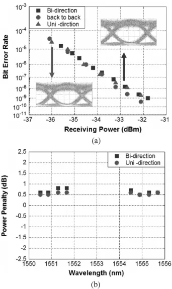
Fig. 4. (a) BER curves and corresponding eye diagrams at channel six and (b) power penalties for all channels of bi- and unidirectional transmission.
and compares them with the back-to-back results. This figure clearly reads that the differences between the power penalty of the bidirectional and unidirectional transmissions were less than 0.2 dB in all channels. A comparison with back-to-back BER curves shows that the sensitivity penalties are under 1 dB in both cases. These experimental results establish the feasi-bility of the bidirectional transmission using the new four-port interleaver. Because the interleaver is designed to cover the whole -band (i.e., 1525–1565 nm), this configuration can accommodate more optical channels within -band, e.g., 16 or 32 channels. Nonetheless, due to the material dispersion of the
birefringent crystal, the current design cannot cover both -and -bands at the same time. Therefore, it will need two types of interleavers, each with different lengths of the birefringent crystal cell, to achieve the task under the same configuration.
IV. CONCLUSION
This letter proposed and experimentally demonstrated a bidi-rectional transmission system that used a novel four-port inter-leaver to enable unidirectional amplification. Given the innova-tive complementary wavelength sensiinnova-tive routing scheme, only a single EDFA is needed to achieve bidirectional transmission. This rerouting configuration in the amplification section pro-vides high gain, low NF, and high OSNR in a bidirectional trans-mission system. After bidirectional transtrans-mission for 210 km, the differences between the bidirectional and unidirectional direc-tions sensitivity penalties were under 0.2 dB in all channels, in-dicating the feasibility of the proposed innovative configuration.
REFERENCES
[1] L. D. Garrett, M. H. Eiselt, J. M. Wiesenfeld, M. R. Young, and R. W. Tkach, “Bidirectional ULH transmission of 160 Gb/s full-duplex ca-pacity over 5000 km in a fully bidirectional recirculating loop,” IEEE
Photon. Technol. Lett., vol. 16, no. 7, pp. 1757–1759, Jul. 2004.
[2] J. Ko, S. Kim, J. Lee, S. Won, Y. S. Kim, and J. Jeong, “Estimation of performance degradation of bidirectional WDM transmission systems due to Rayleigh backscattering and ASE noises using numerical and an-alytical models,” J. Lightw. Technol., vol. 21, no. 4, pp. 938–946, Apr. 2003.
[3] B. Choi and C. Chae, “An asymmetric bidirectional amplifier with all-optical gain control for randomly variable data traffic,” IEEE Photon.
Technol. Lett., vol. 16, no. 1, pp. 287–289, Jan. 2004.
[4] H. S. Chung, J. S. Han, S. H. Chang, and H. J. Lee, “Bidirectional transmissions of 32 channels 10 Gb/s over metropolitan networks using linear optical amplifiers,” IEEE Photon. Technol. Lett., vol. 16, no. 4, pp. 1194–1196, Apr. 2004.
[5] M. D. Feuer, “Measurement of OSNR in the presence of partially po-larized ASE,” IEEE Photon. Technol. Lett., vol. 17, no. 2, pp. 435–437, Feb. 2005.
[6] B. Lyot, “Optical apparatus with wide field using interference of polar-ized light,” C. R. Acad. Sci. (Paris), vol. 195, pp. 1593–1597, 1993. [7] Y. Öhman, “A new monochromator,” Nature, vol. 41, pp. 291–296, 1938. [8] I. ˘Solc, “Birefringent chain filters,” J. Opt. Soc. Amer., vol. 55, pp.
621–624, 1965.
[9] K. Tai, Q. Guo, K. Chang, and J. Chen, “4-port interleavers and fully circulating bi-directional circulators,” in Proc. Optical Fiber
Communi-cation Conf., 2001, pp. MK5/1–MK5/4.
[10] J. Chen, “Dispersion-compensating optical digital filters for 40-Gb/s metro add-drop applications,” IEEE Photon. Technol. Lett., vol. 16, no. 5, pp. 1310–1312, May 2004.
[11] K. M. Feng, M. F. Huang, C. C. Wei, C. Y. Lai, T. Y. Lin, J. Chen, and S. Chi, “Metro add–drop network applications of cascaded dispersion-compensated interleaver pairs using a recirculating loop,” IEEE Photon.