國 立 交 通 大 學
電子工程學系 電子研究所碩士班
碩
士
論
文
開放式存取資料庫的經驗:一個多操作電壓電路設計方法的實作
Experience with OpenAccess Gear:
An implementation of Post-Placement Multi-Supply Voltage Design
Methodology
研 究 生:魏維廷
指導教授:陳宏明 博士
開放式存取資料庫的經驗:一個多操作電壓電路設計
方法的實作
Experience with OpenAccess Gear: An implementation of
Post-Placement Multi-Supply Voltage Design
Methodology
研究生: 魏維廷
Student: Wei-Ting Wei
指導教授: 陳宏明 博士 Advisor: Prof. Hung-Ming Chen
國 立 交 通 大 學
電子工程學系 電子研究所碩士班
碩士論文
A Thesis
Submitted to Department of Electronics Engineering & Institute of Electronics College of Electrical and Computer Engineering
National Chiao Tung University in Partial Fulfillment of Requirements
for the Degree of Master
in
Electronics Engineering January 2008
Hsinchu, Taiwan, Republic of China
開放式存取資料庫的經驗:一個多操作電壓電路設計方法的實作
研究生:魏維廷 指導教授:陳宏明
國立交通大學
電子工程學系 電子研究所碩士班
摘要
在學術界上的實體設計研究,一直以來都是個別的研究群獨立發展。而這會導致 研究整合上的問題。開放存取資料庫是一個完整的資料庫系統,它可以解決這些問 題。另一方面,隨著製程的先進發展,功率消耗已經變成一個很重要的議題。多電壓 電路設計方法提供了一個減少功率消耗的技術。在這篇論文,我們建置了開放式存取 資料庫的環境,採用開放式存取資料庫時序分析器作為我們的基本工具,去實作多電 壓電路設計方法。結果顯示,我們可以在開放式存取資料庫的平台下產生電壓島。 iExperience with OpenAccess Gear:
An Implementation of Post-Placement Multi-Supply Voltage Design
Methodology
Student : Wei-Ting Wei Advisor : Hung-Ming Chen
Department of Electronics Engineering
& Institute of Electronics
National Chiao Tung University
Abstract
Physical design research in academia has been based on infrastructure developed independently, which has resulted in fragmentation problem. OpenAccess, a complete database system, is developed to solve this problem. On the other hand, with technology scaling, power becomes a very important issue. Multiple supply voltage provides an effective technique for power reduction. In this thesis, we build the OA environment and adopt OA Gear Timer as our basic infrastructure to implement MSV design methodology. The experimental results show that we can successfully generate voltage islands based on OA environment.
誌 謝
首先要特別感謝的人,是我的指導教授陳宏明老師。兩年來為我們付出無比 的關懷和耐心,不僅僅是課業上,還有生活待人處事的道理,都使我們獲益良多。 真的很感謝也很高興能有這個機會當陳老師的學生。 同時也感謝口試委員麥偉基教授、江蕙如教授的指導和啟發,讓我在口試時 能夠更進一步的思考,並不僅僅是寫一篇論文而已。 此外,要感謝的是 VDA LAB 實驗室所有的成員,謝謝他們兩年來的砥勵、 幫助及帶給我的歡樂,讓我兩年的生活充滿歡笑及淚水。 家人對我的支持、鼓勵更是我研究路上最大的依靠,對他們的感謝,更是筆 墨難以形容。 最後由衷感謝所有我幫助關懷過我的人。 魏維廷 民國九十七年一月 於新竹 vContents
1 Introduction 1
1.1 Our Contributions . . . 2
1.2 Organization of the Thesis . . . 2
2 OpenAccess and OpenAccess Gear 4 2.1 OpenAccess . . . 4 2.2 OpenAccess Gear . . . 6 2.2.1 OA Gear Timer . . . 6 2.2.2 OA Gear Bazaar . . . 7 2.2.3 Benchmarks . . . 7 2.2.4 Capo Wrapper . . . 7
3 Multiple Supply Voltage Methodology 9 3.1 Voltage Assignment . . . 9
3.2 Voltage Island Grouping . . . 11
3.2.1 Problem definition . . . 11
3.2.2 Tree Algorithm . . . 12
3.2.2.2 Graph Construction . . . 12
3.2.2.3 Tree Construction . . . 14
3.2.2.4 Tree Partitioning . . . 15
3.2.2.5 Tree Reconstruction . . . 17
4 A Case Study: MSV design methodology on OA platform 18 4.1 MSV methodology on OA platform . . . 18
4.2 Experimental Results . . . 20
5 Conclusion and Future Work 24
List of Figures
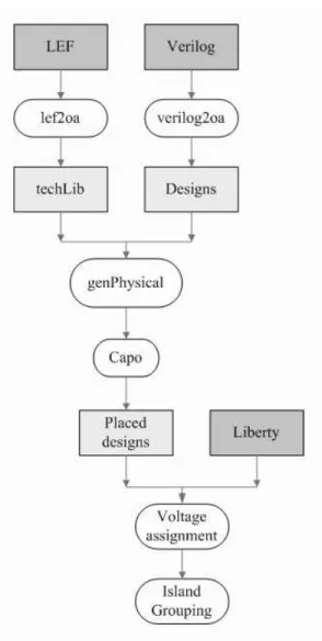
1.1 MSV design flow on OpenAccess platform. . . 3
2.1 The OpenAccess API and Reference Implementation [11]. . . 5
3.1 Multi-Vdd physical design flow. . . 10
3.2 Zero Slack Algorithm [21, 17]. . . 10
3.3 The flow of Tree-Algorithm [8]. . . 13
3.4 Graph construction [8]. . . 14
3.5 The algorithm of building a binary tree [8]. . . 15
3.6 Multi-level clustering procedure. (a)First merging. (b)Second merg-ing. (c)Result of first level clustermerg-ing. (d)Graph after first level clus-tering. . . 16
3.7 The final binary tree T that represents multi-level clustering proce-dure. . . 17
3.8 An optimal tree partition with five subtrees, each subtree represents a voltage island. . . 17
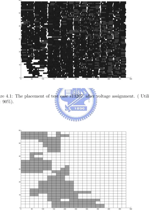
4.1 The placement of test case s13207’ after voltage assignment. ( Uti-lization: 90%). . . 23
List of Tables
4.1 The information of five test cases. . . 20
4.2 The experimental results of five test cases. . . 21 4.3 The run time of five test cases. . . 22
Chapter 1
Introduction
The development of CAD tools is highly fragmented today. Individual researchers or tool developers implement their own infrastructure. This fragmentation problem results in a significant effort for researchers to integrate individual infrastructure builded in different design databases. Hence, a common database is required.
There are many mature design databases existed in EDA industry today [13], such as OpenAccess, Milkyway(from Synopsys), MAP-in Program (from Synop-sys), Falcon(from Mentor), and Magma Design Automation. Among these design databases, Milkway, Falcon, and Magma are not publicly available. MAP-in Pro-gram is free, but it does not support access to timing or RC parasitic data. OpenAc-cess(OA) does not currently support for timing now, but OA provides extensions which allow objects in the database to be annotated with arbitrary data. OA is now an open-source platform.
OpenAccess(OA) database was developed to provide a common EDA infrastruc-ture for physical design tools [2, 6]. It is a complete database for IC design. It contains comprehensive data model to support the needs of applications for IC de-sign. An important feature of OA is that it supports extensibility. Inside OA, there exists OpenAccess Gear(OA Gear), which is a source library that extends the util-ity of OA database with a set of common tools and applications. OA Gear includes
static timer and placer interface.
On the other hand, with technology scaling, power issue becomes more and more important in modern circuit designs. Among the various techniques for low power design, multiple supply voltage (MSV) [19] provides an effective technique for power reduction. In a MSV design, assign High-Vdd to cells on critical path and Low-Vdd to cells on non-critical path to reduce power. MSV has been applied at various design stages such as the placement stage [15], the post-placement stage [8, 20, 21], the floorplanning stage [12, 14], and the post-floorplanning stage [16]. We focus on the post-placement stage. MSV during the post-placement stage consists of two steps: voltage assignment and voltage island grouping.
In this thesis, we build the OA environment and give a case study on MSV with OA API, OA Gear Timer, Capo Wrapper, and some translators provided by OA. For MSV designs, we applied the zero slack algorithm(ZSA) [21, 17] and tree-based algorithm [8] for voltage assignment stage and voltage island grouping stage.
1.1
Our Contributions
In this thesis, we study OpenAccess and implement a MSV physical design flow on OA platform. First, we translate the standard data files to OA database. Second, we use Capo to place the cells. Finally, we perform voltage assignment on the post-placed designs and generate voltage islands. The complete flow is shown in Figure 1.1.
1.2
Organization of the Thesis
The rest of this thesis is organized as follows. Chapter 2 gives an introduction of OpenAccess and OpenAccess Gear. Chapter 3 introduces the multiple supply voltage design methodologies. Chapter 4 gives a case study on OA platform and
Figure 1.1: MSV design flow on OpenAccess platform.
Chapter 2
OpenAccess and OpenAccess Gear
In this chapter, we will introduce OpenAccess and OpenAccess Gear system, and describe the functionality provided by OpenAccess Gear.
2.1
OpenAccess
OpenAccess is an advanced EDA database system designed to enable interoper-ability among IC design tools. OpenAccess consists of open standard data access interface(API) and Reference Implementation of the API, as shown in Figure 2.1. The implementation was donated by Cadence Design Systems, and are now man-aged by the OpenAccess Coalition(OAC), an group of over 30 companies, including some of the top players in EDA and semiconductors. OpenAccess is also a complete data model. It consists of logical and physical domains. It includes floorplanning information, routing topology, scan chains, etc. It can be used to represent designs from post-synthesis netlists to tapeout.
OpenAccess provides advantage to developement of physical design methodolo-gies. Today, many design flows use common file formats such as Verilog, DEF and GDSII between different tools. However, these files are usually incomplete and the translation between these design files and applications is very time consuming. Take Verilog code as an example, it can only represent the logical information of
Figure 2.1: The OpenAccess API and Reference Implementation [11].
design. In the later placing and routing stage, Verilog code must be transferred to the databases used in the specific APR tool, which is time consuming. OpenAceess can solve these problems since OA data model is more complete. In addition, OA database can be read by applications through the API. It is much more efficient than file translation. Another advantage of OpenAccess is the increased ease of code reuse [18]. Once an model is defined with OA data model, it can be used as a part of larger OA-based applications without conversions from one data representation to another. It is very beneficial to academia.
OpenAccess also contains a set of translators to and from common existing file formats, such as Verilog, LEF, DEF and GDSII. It is very useful for tool developers on OA. Today, many companies are working with OA, such as IBM, AMD, HP, LSI, and so on. LSI is using OpenAccess in its RapidWorx design flow [10]. IBM is also using OA 2.2 based tools in the custom design flow [5]. The first release of OpenAccess was OA 2.0 in January 2003, OA 2.1 followed in June 2003. OA 2.2 was released in October 2004 [11].
2.2
OpenAccess Gear
OA Gear is written in C++, and it is fully open-sourced. OA Gear contains four components. We describe these four components in this section.
2.2.1
OA Gear Timer
The first component is OA Gear Timer. OA Gear Timer is a static timing analysis tool provided by OA Gear. OA Gear Timer supports incremental timing analysis, industry-standard timing library format and extensible wire-delay modeling. We briefly describe some main features of OA Gear Timer as below. More details can be seen in [22].
1. Timing mode
OA Gear Timer has two timing modes, full timing mode and incremental tim-ing mode. Full timtim-ing mode analysis computes and stores the arrival and required times of all nodes in the design. Incremental timing mode only com-putes timing for a minimal subset of nodes of the design.
2. Wire delay modeling
There are two wire delay models in OA Gear Timer currently. One ignores wire delays, and the other uses the half-perimeter bounding-box to estimate delay and load.
3. Standard file formats
OA Gear Timer supports the standard timing library formats offered by Ca-dence(.tlf) and Synopsys(.lib). For timing constraints, OA Gear Timer support a useful set of .sdc file format. Some important .sdc commands, such as setting the clock period, creating external delays on primary inputs and outputs are all available.
4. Timer-Database Integration
OA extensions(appDef) allow objects in the database to be annotated with arbitrary data. OA Gear Timer uses this to store the timing information. The instance terminals on all instances in a design are given an appDef to store the arrival and required times.
2.2.2
OA Gear Bazaar
Visualization is important for debugging in physical design, like placement and rout-ing. OA Gear provides the graphical user interface(GUI), called Bazaar. Bazaar contains two visualization tools. One is layout viewer, which displays a physical layout of a design. The second is a netlist browser, which shows simple shapes of the instances. It will help designers to verify the connectivity of the netlist. All GUI components are programmed using QT, a cross-platform graphics toolkit [3], and are designed to be flexible.
2.2.3
Benchmarks
OA Gear provides two categories of benchmarks, freely distributed benchmarks and restricted benchmarks. The first kind is freely available for all users. It consists of a standard cell library(.lib) and the ISCAS89 sequential logic benchmarks. The second kind is restricted for use in non-commercial settings only. The designs for this benchmark suite come from the Faraday Structured ASIC test cases [1].
2.2.4
Capo Wrapper
OA Gear utilizes Capo [9, 7] as the placement tool, and constructs a wrapper around Capo. The main operations of the wrapper are summarized as followed:
2. Generate the Capo internal data structure . 3. Invoke Capo placer.
Chapter 3
Multiple Supply Voltage
Methodology
Multiple supply voltage(MSV) is an effective method to reduce dynamic power. In a MSV design, we assign High-Vdd to cells on critical path and Low-Vdd to cells on non-critical path to reduce power. However, MSV design results in complex power networks which increase design cost. Therefore, it is desired that cells of different supply voltages are grouped into a smaller number of voltage islands. The MSV physical design flow consists of two stages. First, we assign cells on non-critical path to Low-Vdd to save power consumption. Second, we generate voltage islands to reduce the complexity of power supply networks. The flow is shown in Figure 3.1. We describe voltage assignment stage and voltage island grouping stage in this chapter.
3.1
Voltage Assignment
In this stage, we must try to assign lower voltage to cells without degrading design performance to reduce power. Cell delays increase with reduced supply voltages,
and the former can be formulated as a linear function of the latter, when VddH-VddL
is small [4], as shown in Equation 3.1 [21]:
Figure 3.1: Multi-Vdd physical design flow.
where k is a constant for each cell, and d is cell delay. Assigning a lower voltage to a cell without violating timing constraint is equivalent to distributing delay budget to the cell. Then, voltage assignment problem can be formulated into delay budgeting problem. We use zero slack algorithm(ZSA) [17, 21] to perform voltage assignment. ZSA iteratively assigns delay budget to non-critical cells in the circuit. Zero slack algorithm is shown in Figure 3.2.
3.2
Voltage Island Grouping
After the voltage assignment, we get the voltage supply requirement of all the cells. To reduce the complexity of power networks, we generate voltage islands in this stage. We use Tree-Algorithm proposed in [8] to generate voltage islands. The details are presented in the following subsections.
3.2.1
Problem definition
Given an m × n grid based placement P of N cells which has been assigned different Vdd in previous stage. Let A be an m × n array, and A[i][j ], the value of the element at position (i,j ), 1 ≤ i ≤ m, 1 ≤ j ≤ n, represents the dynamic power at the the point. Each cell will occupy an integral number of elements in A. The voltage island generation problem is to partition the array A into a set of connected regions Π
= { R1...Rk } such that the size of the partitioning Π is as small as possible and
total power wastage ω(Π) does not exceed a given threshold. µ and ω are defined as followed.
The maximum power required in region R is defined as:
µ(R) = max
The power wastage of a region R is defined as:
ω(R) = X
(i,j)∈R
(µ(R) − A[i, j]) (3.3)
Total power wastage of Π is defined as:
ω(Π) = X
1 ≤ t ≤ k
ω(Rt) (3.4)
We define the voltage-partitioning problem the same as [8] as follows: Non-rectangular Voltage-partitioning problem
Given a m × n array A and an error threshold δ, find a partitioning Π of connected regions whose weight ω(Π) is at most δ and the size Π is as small as possible.
3.2.2
Tree Algorithm
We use the Tree-Algorithm proposed in [8] to generate voltage islands. An overview of the Tree-Algorithm flow is shown in Figure 3.3. We just briefly describe the Tree-algorithm in this section. More details can be seen in [8].
3.2.2.1 Grid Coarsening
In order to reduce space requirement, we coarsen the original grid-based array A to array A’, as shown in Figure 3.4(b). To further reduce the size, we combine the neighboring elements that belong completely to the same cell to an element. This step is reasonable because that a cell should belong to only one voltage island at the end. The coarsening step will bring some power wastage.
3.2.2.2 Graph Construction
We then construct a graph G(V,E) from A’. Each node v represents a element in array A’ and edge e(u,v) represents that node u and node v are neighbors each othert in array A’. Each node u in G have a cost cost(u), a size size(u) that denotes
Figure 3.4: Graph construction [8].
the number of A’s elements contained in u and a µ(u) that denotes the maximum power required at u.
3.2.2.3 Tree Construction
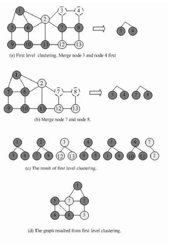
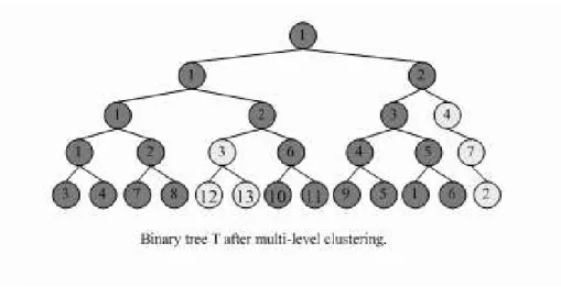
After graph construction, we perform a bottom-up clustering on G recursively. At each level, pairs of adjacent nodes are clustered to form a super-node. A binary tree T, which represents the multi-level clustering, is constructed finally. We give an example, as shown in Figure 3.6. At the first level clustering, node 4 is selected because that node 4 has minimum number of neighbors. Node 3 has the minimum incurred power wastage among all the neighbors of node 4. Hence, node 4 and node 3 are merged to a super-node which is used in the next level. It is shown is Figure 3.6(a). After the first level clustering, there are seven super-nodes for second level clustering, as shown in Figure 3.6(c). At the second level clustering, the graph is as shown in Figure 3.6(d). After the multi-level clustering, a binary tree is constructed. The binary tree T represents the clustering process, as shown in Figure 3.7. The
Figure 3.5: The algorithm of building a binary tree [8].
detail algorithm is shown in Figure 3.5.
3.2.2.4 Tree Partitioning
Dynamic programming approach is applied to partition the tree T into a set of
subtrees T1...Tk such that every node is contained in one subtree, k is the smallest
possible, total cost is smaller than a given threshold. The value k represents the number of voltage islands. Figure 3.8 is an example of tree partition.
Figure 3.6: Multi-level clustering procedure. (a)First merging. (b)Second merging. (c)Result of first level clustering. (d)Graph after first level clustering.
Figure 3.7: The final binary tree T that represents multi-level clustering procedure.
Figure 3.8: An optimal tree partition with five subtrees, each subtree represents a voltage island.
3.2.2.5 Tree Reconstruction
We iteratively reconstruct the tree the re-partition it. The tree reconstruction step is
the same as the “BuildTree()” procedure except the starting vertex set S = {r1...rk}
where ri is the root of a subtree resulted from the partitioning in the last iteration.
Chapter 4
A Case Study: MSV design
methodology on OA platform
We have introduced OpenAccess and MSV design methodology in Chapter 2 and Chapter 3. In this chapter, we implement the MSV on OA platform. The flow of our implementation is shown in Figure 1.1. We will describe the details steps in this chapter.
4.1
MSV methodology on OA platform
We study OpenAccess and build OA environment. We select MSV design as our case study on OA platform. We first translate the design files to OA database and place the design. Then perform voltage assignment and generate voltage islands at the end. The details are shown as in this section.
Voltage islands generation problem
Given a gate-level netlist and technology library, we want to lower down the voltage of non-critical cells to reduce power. To reduce complex power networks, we partition the design with dual voltages into a set of connected regions, such that the number of connected regions is as small as possible and total power wastage does not exceed a given threshold.
the two translators, verilog2oa and lef2oa, to translate original design and technology library to OA database. Second, we must generate physical information of the design. OA Gear comes with a program called “genPhysical” which can convert an “oacNetlist” view to an “oacMaskLayout” view. This conversion is necessary since OA Gear Timer uses oaMaskLayout view. In addition, the program generates an appropriate core size for the design and primary input/output positions around the periphery randomly. Then, we use Capo-Wrapper, one of the important components in OA Gear package, to invoke Capo to place the design.
After the placement, we have got the post-placed design. We use OA Gear Timer as the basic timing engine which is needed in this stage. We first find the worst slack of the post-placed design and take the value as the timing constraint. We formulate voltage assignment problem as delay budgeting problem, and apply ZSA [21, 17] to perform voltage assignment. OA Gear Timer contains two timing modes: full timing mode and incremental timing mode, as described in Chapter 2. We perform full timing mode for registers, and incremental mode for the other cells.
After the voltage assignment, we can get the voltage supply requirement of each cell. To reduce the complex power networks, we have to group cells into voltage islands. Our goal is to partition the m×n placement into a set of connected regions such that the size of the partitioning Π is as small as possible and total power wastage
ω(Π) does not exceed a given threshold. We apply Tree algorithm [8] to generate
voltage islands. We first coarsen the original m×n array A to a smaller m’×n’ array
A’ and construct a graph G(V,E) from A’, where we set m’=m
2 and n’=k
q
m×n
N . N
represents the number of cells, and k is a variable used to control the coarsening
power wastage, Pwastage1. The power wastage is computed as a certain percentage of
the maximum power increase, which corresponds to the total power increase when
the voltages of all the cells are raised to V ddH, similar as [8]. We set k about
increase k and re-coarsen the array A. After coarsening step, we perform a bottom-up clustering on G recursively, and a binary tree is constructed. Then, we set the
partition threshold δ = (1-Pwastage1) ∗ 0.5 to partition the tree into a set of
sub-trees, where each sub-tree represents a voltage island. After partitioning step, we iteratively construct the tree and re-partition it. Finally, we legalize the solution. We show the experimental results in the following section.
4.2
Experimental Results
We implement the MSV in the C++ Programming language with OA and OA Gear API. The platform is on Linux based machine with Intel 3.0GHz CPU and 4 GB memory. The set of test cases we used is from ISCAS89 benchmarks, part of OA Gear components. We use another liberty because that the liberty in OA Gear does not support multiple supply voltage. The design requires little modifications because some gates used in original design is not provided in the liberty we used. For example, we replace the original ”OR3” gate with two ”OR2” gates. Table 4.1 shows the detailed information of the set of test cases. For each test case, the first column gives the test case circuit name, “#Cells” shows the number of instances, “#Registers” gives the number of registers. s13207’ represents the modified design from s13207.
Table 4.1: The information of five test cases.
Case #Cells #Registers
s13207’ 4014 466
s15850’ 6806 540
s35935’ 15487 1728
s38417’ 21151 1463
s38584’ 17490 1292
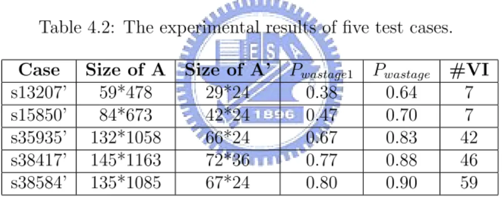
where A is the array that represents the original grid-based placement. “Size of A’ ”
shows the size of array A’, where A’ is the new array after coarsening step, “Pwastage1
” gives the power wastage after size coarsening. After size coarsening, we may pull up the voltages of cells, which also results in power wastage. We set this amount of
power wastage as “Pwastage1”. “Pwastage” shows the power wastage resulted from the
coarsening and merging step, “#VI” gives the number of voltage islands. We take case s13207’ for example, the original grid-based placement A is an 59×478 array. After coarsening step, we get a new 29×24 array A’ with 38% power wastage. After the final clustering step, the total power wastage is 64%, and the number of voltage islands is 7.
Table 4.2: The experimental results of five test cases.
Case Size of A Size of A’ Pwastage1 Pwastage #VI
s13207’ 59*478 29*24 0.38 0.64 7
s15850’ 84*673 42*24 0.47 0.70 7
s35935’ 132*1058 66*24 0.67 0.83 42
s38417’ 145*1163 72*36 0.77 0.88 46
s38584’ 135*1085 67*24 0.80 0.90 59
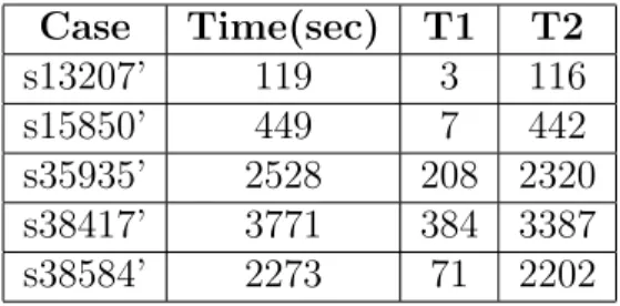
Table 4.3 shows the run time. “Time” gives the total run time, “T1” shows the run time of voltage island generation stage, “T2” shows the run time of voltage assignment stage. In the voltage assignment stage, static timing analysis is required. We use OA Gear Timer as our timing engine. We perform full timing mode for registers, and incremental mode for other cells. From the experimental results, we can find that most of the run time is spent on voltage assignment stage. This is because that full timing analysis is required for registers.
Figure 4.1 and Figure 4.2 shows the result of test case s13207’. Figure 4.1 gives the placement after voltage assignment, we set the utilization 90%. Figure 4.2
Table 4.3: The run time of five test cases. Case Time(sec) T1 T2 s13207’ 119 3 116 s15850’ 449 7 442 s35935’ 2528 208 2320 s38417’ 3771 384 3387 s38584’ 2273 71 2202
Figure 4.1: The placement of test case s13207’ after voltage assignment. ( Utiliza-tion: 90%).
Chapter 5
Conclusion and Future Work
In this thesis, we study OpenAccess and OpenAccess Gear, and we implement a MSV design flow with OA API and OA Gear. First, we translate the design and library to OA database and invoke Capo to place the cells through Capo Wrapper. Then, we apply zero slack algorithm to perform voltage assignment on post-placed design. To reduce the complex power networks, we generate voltage islands at the end. The results show that we can successfully generate voltage islands with OA-based infrastructure.
Our future problem is to integrate a timing driven placer to OA platform. It will be very helpful to make the MSV design flow on OA platform more completely. In the other hand, in the voltage assignment stage, physical proximity can be added into ZSA, which may result in better proximity. Another future problem is about flow issue. In our flow, we perform voltage assignment after placement. We may change the flow a little. If we perform voltage assignment before placement, we can put the slacks of cells into the weight of the placement to let the critical cells be placed as close as possible. This may result in less power wastage and less number of voltage islands.
Bibliography
[1] http://www.faraday-tech.com/. [2] http://www.openeda.si2.org/. [3] http://www.trolltech.no/.
[4] Synopsys liberty user guide. version 2003.12.
[5] K. Barkley. “IBM: OpenAccess Adoption from End Users Perspective”. In
OpenAccess Conference, pages 434–436, Nov 2005.
[6] T. Blanchard, R. Ferreri, and J. Wilmore. “The OpenAccess Coalition: The drive to an open industry standard information model, API, and reference im-plementation for IC design data”. In Proc. of ISQED, pages 69–74, 2002. [7] A. E. Caldwell, A. B. Kahng, and I. L. Markov. “Can recursive bisection alone
produce routable placements?”. In Proc. of DAC, pages 477–482, 2000.
[8] R. Ching, E. Young, K. Leung, and C. Chu. “Post-Placement Voltage Island Generation”. In Proc. of ICCAD, pages 641–646. 2006.
[9] S. N. Adya et al. “Unification of partitioning, placement and floorplanning”. In Proc. of ICCAD, pages 550–557, 2004.
[10] R. Goering. “OpenAccess adoption challenging but worth it”. In EETimes, Nov 2004.
[11] M. Guiney and E. Leavitt. “An introduction to OpenAccess: an open source data model and API for IC design”. In Proc. of ASP-DAC, pages 434–436, 2006.
[12] J. Hu, Y. Shin, N. Dhanwada, and R. Marculescu. “Architecting Voltage Islands in Core-Based System-on-a-Chip Designs”. In Proc. of ISLPED, pages 180–185, 2004.
[13] Lavagno, Martin, and Scheffer. “Electronic Design Automation For Integrated Circuits Handbook”. Baker & Taylor Books, 2006.
[14] W.-P. Lee, H.-Y. Liu, and Y.-W. Chang. “Voltage Island Aware Floorplanning for Power and Timing Optimization”. In Proc. of ICCAD, pages 389–394, 2006. [15] B. Liu, Y. Cai, Q. Zhou, and X. Hong. “Power Driven Placement with Layout Aware Supply Voltage Assignment for Voltage Island Generation in Dual-Vdd Designs”. In Proc. of ASP-DAC, pages 582–587, 2006.
[16] W.-K. Mak and J.-W. Chen. “Voltage Island Generation under Performance Requirement for SoC Designs”. In Proc. of ASP-DAC, pages 798–803, 2007. [17] R. Nair, C. L. Berman, P.S. Hauge, and E. J. Yoffa. “Generation of performance
constraints for layout”. In IEEE TCAD, pages 860–874, 1989.
[18] D. Papa, I. Markov, and P. Chong. Utility of the openaccess database in academic research. In Proc. of ASP-DAC, pages 440–441, 2006.
[19] K. Usami and M. Horowitz. “Clustered Voltage Scaling Technique for Low-Power Design”. In Proc. of ISLPED, pages 3–8, 1995.
[20] H. Wu, I.-M. Liu, M. Wong, and Y. Wang. “Post-Placement Voltage Island Generation under Performance Requirement”. In Proc. of ICCAD, pages 309– 316, 2005.
[21] H. Wu, M. Wong, and I.-M. Liu. “Timing-Constrained and Voltage-Island-Aware Voltage Assignment”. In Proc. of DAC, pages 429–432, 2006.
[22] Z. Xiu, D. Papa, P. Chong, and C. Albrecht. “Early Research Experience With OpenAccess Gear: An Open Source Development Environment For Physical Design”. In Proc. of ISPD, pages 94–100, 2005.
作者簡歷
魏維廷,民國七十二年一月出生於台南市。民國九十四年六月畢業於中正大 學電機工程學系,並於同年九月進入國立交通大學電子研究所就讀,從事 VLSI 實體設計方面相關研究。民國九十七年一月取得碩士學位,碩士論文題目為『開
![Figure 2.1: The OpenAccess API and Reference Implementation [11].](https://thumb-ap.123doks.com/thumbv2/9libinfo/8749384.205577/14.918.277.618.153.495/figure-openaccess-api-reference-implementation.webp)
![Figure 3.2: Zero Slack Algorithm [21, 17].](https://thumb-ap.123doks.com/thumbv2/9libinfo/8749384.205577/19.918.188.699.478.1043/figure-zero-slack-algorithm.webp)
![Figure 3.3: The flow of Tree-Algorithm [8].](https://thumb-ap.123doks.com/thumbv2/9libinfo/8749384.205577/22.918.156.746.318.910/figure-the-flow-of-tree-algorithm.webp)
![Figure 3.4: Graph construction [8].](https://thumb-ap.123doks.com/thumbv2/9libinfo/8749384.205577/23.918.149.740.152.695/figure-graph-construction.webp)