行政院國家科學委員會專題研究計畫 成果報告
鈑金材料異向性及可成形性之理論研究與應用(II)
研究成果報告(精簡版)
計 畫 類 別 : 個別型 計 畫 編 號 : NSC 97-2221-E-151-023- 執 行 期 間 : 97 年 08 月 01 日至 98 年 07 月 31 日 執 行 單 位 : 國立高雄應用科技大學模具工程系 計 畫 主 持 人 : 許進忠 計畫參與人員: 碩士班研究生-兼任助理人員:李政昕 碩士班研究生-兼任助理人員:梁文鍾 碩士班研究生-兼任助理人員:蘇賢修 碩士班研究生-兼任助理人員:蘇冠丞 碩士班研究生-兼任助理人員:毛建豐 碩士班研究生-兼任助理人員:賴恆得 博士班研究生-兼任助理人員:佘征諴 報 告 附 件 : 出席國際會議研究心得報告及發表論文 處 理 方 式 : 本計畫涉及專利或其他智慧財產權,2 年後可公開查詢中 華 民 國 98 年 07 月 27 日
行政院國家科學委員會補助專題研究計畫
▓ 成 果 報 告
□期末進度報告
鈑金材料異向性及可成形性之理論研究與應用(2)
計畫類別:▓ 個別型計畫 □ 整合型計畫
計畫編號:NSC 97-2221-E-151 -023C012-2
執行期間:
97 年 8 月 01 日至 98 年 7 月 31 日
計畫主持人:許進忠
共同主持人:
計畫參與人員:余征諴、李政昕、梁文鍾、蘇賢修、蘇冠丞、毛建豐、
賴恆得
成果報告類型(依經費核定清單規定繳交):▓精簡報告 □完整報告
本成果報告包括以下應繳交之附件:
□赴國外出差或研習心得報告一份
□赴大陸地區出差或研習心得報告一份
;出席國際學術會議心得報告及發表之論文各一份
□國際合作研究計畫國外研究報告書一份
處理方式:除產學合作研究計畫、提升產業技術及人才培育研究計畫、列管計
畫及下列情形者外,得立即公開查詢
□涉及專利或其他智慧財產權,□一年;二年後可公開查詢
執行單位:國立高雄應用科技大學
中 華 民 國 98 年 7 月 31 日
摘要
本計畫主要目的在擴展基礎理論研究,並應用於工業界中之碟型天線精密
模具設計,第二年將考慮多參數(七個角度值)之異向性理論,探討不同異向性
模式(平均、三軸與七角度)對鈑金成形性與彈回之關係,與不同模式之分析精
確度。以拉伸實驗測定更多角度(每 15 度量測一次)之異向性,以線性內插將
多方向異向性理論導入應變能量法中,預測應變及彈回量。衝壓品將推廣到雙
曲率且具有直線或圓弧凸緣,因而可應用於雙曲率圓盤天線成形分析。以所發
展之影像處理程式量測具凸緣圓杯引伸尺寸,驗證應變能量法及有限元素分析
之預測精度。本年度整合多參數(七個角度值)之異向性理論、具雙曲率及凸緣
(直線或圓弧)產品輪廓,更具有實用性。
關鍵字: 異向性、破壞理論、應變能量法、影像處理技術、彈回分析、有限元
素法
ABSTRACT
This project is aimed at the development of basic anisotropic and fracturing
theories, and the applications. The developed theories will be applied to the
precision die design of industrial products, such as the disk antenna. In the first year,
the research work is focused on the development of the anisotropy and the fracture
criterion. The tensile and single curvature semi-sphere drawing tests will be
designed and carried out to determine the parameters of anisotropy and fracture
criterion with the consideration of elastic deformation. The planar anisotropy model
will be integrated into the axisymmetrical strain energy method. The forming
process and the spring-back effect will be analyzed. A FEM program will be
adopted to do the detail analysis and compare with the results of strain energy
method. The experimental results will be measured via a precision four-axis CMM
to evaluate the theoretical models and analysis results. An image processing
program will be developed to measure the major dimensions of the tested
specimens. This research differs with the other researchers’ works mainly at the
integration of the elastic deformation, anisotropy, fracture criterion and the strain
energy theories.
KEYWORDS: anisotropy, fracture criterion, strain energy method, image
processing technology, FEM
一、前言
金屬鈑金成形中,影響沖壓成形的因素有許多,而隨著產業科技的進步,對產品的精 度要求也隨著提高,此時便浮現許多難解的問題。鈑金以滾軋方式生產,於引伸成形時, 會受到本身異向性的影響,在各個角度所造成的應變變形量不相同,導致成形品邊緣出現 高度起伏變化,一般稱此現象為凸耳或耳緣現象。對於目前的現況,受限於鈑金材料製造 方式,無法去除異向性性質,因此在金屬材料異向性的研究上,許多國內外學者一直以各 種方法進行理論探討。2001 年,Xue等人[1][2]以能量法預測對稱及非相等雙曲率成形之彈 回,以薄膜原理及薄殼旋轉及能量法考慮彎曲與彎曲卸彎過程,以半球形模具及沖頭近似 分析在中立面上圓周方向分佈之薄膜應變,以塑性變形理論表示應力及應變關係,導出薄 膜之整體應變能量,以最佳化方法求出最小變形能量場,在彈回時,將彈性變形項去除, 加上彈性變形虎克定律建立相對應力,在滿足幾何相適性下,可算出彈回後幾何。Hu等人 [3]將Barlat-Lian異向性準則以彈塑性變形及一種分離的Kirchhoff三角網格模型,導入 quasi-flow corner theory,並配合有限元素分析,發現深引伸成形時,異向性對於凸耳有相 當的影響,如凸耳的大小、數目、位置等,但是材料加工硬化指數只與凸耳的大小有關, 而不與凸耳的數目和方向有關。於 2002 年,Hu[4]等人把異向性當作一重要因素,探討各 種不同之鈑金成形之影響,並根據Hill提出之論點,將異向性關係導入等效應變表示式內, 有效的表現出異向性對鈑金成形的影響。2005 年,Chamanfar[5]等人根據Danckert所提理 論,考慮體積改變之影響,定義更接近於實際情形的r值表示法。2006 年,Yoon[6]提出新 的材料異向性準則,發現其所使用之鈑料於圓杯分析後可得到 8 個凸耳,比起Lankford異 向性模式更能貼近真實情況。2007 年,Engler等人[7]發現不同的鋁合金鈑材經圓杯引伸後, 由於材料內部塑性多晶體的差異,而會有不同數量的凸耳現象發生,故研判塑性多晶體的 位置、大小與凸耳發生的位置及數量有密切的關係。2008 年 Agrawal等人[8]提出應用upper bound method 將正規化後的異向性R值導入,進而有效最佳胚料,降低引伸後的凸耳發生。 表1 目前計畫研究成果之載具說明 成品幾何特徵 理論推導 剖面(子午 線)輪廓 圓周輪 廓外形 異向性理論 R 值量測方式 能量法 驗證載具(成品) 無凸緣 具 反曲雙曲 率 在零度 及九十度 斷面 橢圓 三個及七個角度 之異向性。 使用影像處理量 測 值,拉伸實 驗證 值。 非軸對稱模 式, 值使用線 性內插 , ( ) R 驗 R R 具凸緣,具 反曲雙曲 率 圓形 三個及七個角度 測 驗證R 值。 式, 線 性內插 之異向性。 使用影像處理量 R 值,拉伸實驗 非軸對稱模 R 值使用峰 峰 谷 圖1 因異向性所造成的凸耳現象 本年度計劃研究工作為完成多參數(七個角度值以上)之異向性理論,推導具凸緣及反曲之雙 曲率幾何成形分析理論,探討異向性及成形性之關係及對彈回之影響,建立鈑金材料異向 性因子與材料角度之關係式。並將多參數異向性理論導入應變能量法中,使用內插方式考 慮不同角度之異向性,將其導入應變能量法中,以建立更為精確的應變預測及彈回量預測。 比較三角度異向性有限元素分析之精度,進行圓杯引伸實驗,以所發展之影像處理程式量 測引伸杯尺寸,驗證不同異向性理論之適用性。 材料性質試驗結果 本研究選用中鋼生產之SPCC-CQ#2 成形加工用軟鋼進行 FEM 成形分析,將其鈑料進行拉 伸試驗並求得材料參數,其實驗所得之材料參數如下表所示: 表2 SPCC 軟鋼之材料性質表 材料 SPCC 材料密度 7.85E-09[Ton/mm3] 楊氏係數, E 2.07E+05 [MPa] 浦松比, ν 0.369 材料強度係數, k 413.196 [MPa] 加工硬化指數, n 0.219 降伏應力 139.40 [MPa] 降伏應變 0.0015 0 度異向性數值, R(0) 1.862 15 度異向性數值, R(15) 1.773 30 度異向性數值, R(30) 1.348 45 度異向性數值, R(45) 1.088 60 度異向性數值, R(60) 1.348 75 度異向性數值, R(75) 1.467 90 度異向性數值, R(90) 2.023
電腦輔助成形分析系統 本研究根據能量法理論分析,為快速得到結果,利用物件導向程式編輯軟體(Borland C++ Builder)建立一理論分析程式介面,分成模具參數及鈑料設計模組與成形應變分析模組,只 要輸入模具資訊與最佳化參數,即可進行能量法理論分析。如圖X 所示 影像及資料顯示區 模具參數設定 胚料網格設定 圖2 模具參數及鈑料設計模組 最佳化參數設定 材料性質設定 圖3 成形應變模組
圓杯引伸成形實驗 為驗證其本研究所提出之理論方法,本研究中將規劃與理論分析模型相同之無凸緣之圓杯 引伸實驗以驗證所推導之多角度異向性之能量法。金屬鈑料在引伸成形過程中,由於受到 鈑料本身異向性(Anisotropy)之影響,料片各角度之變形比不同,而造成成品邊緣高低不平, 此現象被稱為凸耳現象,為觀察材料異向性對於引伸後成品邊緣高低誤差的影響,在經過 數值跟CAE 分析後,進而規劃引伸試驗來對理論及 CAE 分析之結果做驗證。 壓料彈簧 沖頭 壓料鈑 200 240 單位:mm 頂出餅 圖4 具模緩衝裝置之單動式引伸模具圖(3D&2D) 沖頭 壓料彈簧 壓料鈑 (a)開模狀態 (b)合模狀態 圖5 圓杯引伸成形模具 圓杯影像量測實驗 本研究發展影像處理量測,設計一量測平台,搭配所撰寫之影像處理程式,量測引伸杯之 應變,其量測架構如圖6所示,分別於上方及右方設置CCD,以從兩方向來拍攝來源影像, 圖6 圓杯引伸量測平台及影像 CCD1 CCD2
圓杯引伸能量法成形分析結果 為了驗證程式的分析結果,並了解異向性對成形的影響,本研究以圓杯引伸對產品進行分 析,並與有限元素分析結果作比較,由於使用的圓杯引伸模型為對稱模型,分析時將只針 對1/4 模型進行模擬,其模型如圖 7所示。 項目 尺寸 沖頭直徑,Pd 33.6 mm 沖頭圓角,Pr 4.0 mm 母模直徑,Dd 36.0 mm 母模圓角,Dr 4.5 mm 衝頭與母模間隙 1.2 mm 胚料半徑,Br 30.0 mm 胚料厚度,t 1.0 mm 沖頭 壓料鈑 母模 鈑料 Dd/2 Pd/2 Pr Dr X Y Z Br 圖7 有限元素之分析模型與各零件尺寸 以FEM與EM執行圓杯引伸分析,首先為平均異向性模式,在此模式下,於各個角度發生的 應變皆會相同,圖8為SPCC材料於平均異向性模式下,子午線方向的徑向應變,能量法與 FEM分析結果比較之下,其應變趨勢十分相近,顯示本研究所提出之方法是可行的。 SPCC-平均異向性-子午線徑向應變 -0.1 0 0.1 0.2 0.3 0 5 10 15 20 25 30 35 成形後沿斷面距中心點之距離 (mm) 子午線軸向應變 (EpsilonPhi) EM FEM 圖8 SPCC 平均異向性模式引伸成形之子午線方向應變比較圖
圖9與圖 10為SPCC材料於平面異向性模式之下,相對於滾軋方向 0 度與 90 度斷面沿子午 線方向的應變曲線圖,可看出能量法分析之應變與有限元素分析之結果趨勢相近。而誤差 較大的地方為沖頭圓角處,在側壁處應變皆往上提昇且在下模圓角處受到材料增厚的影 響,應變開始下降。且在能量法中,只考慮成形前與成形結束後的狀態,並未加入壓鈑力, 而在有限元素分析中可解決此一問題,使得兩者在分析結果上,有限元素分析結果會有較 長的變形長度。 SPCC-平面異向性-子午線軸向應變 (0度) -0.1 0 0.1 0.2 0.3 0 5 10 15 20 25 30 35 成形後沿斷面距中心點之距離 (mm) 子午線軸向應變 (EpsilonPhi) EM FEM 圖9 SPCC-平面異向性模式-成形後子午線方向應變比較圖(0 度) SPCC-平面異向性-子午線軸向應變 (90度) -0.1 0 0.1 0.2 0.3 0 5 10 15 20 25 30 35 成形後沿斷面距中心點之距離 (mm) 子午線軸向應變 (EpsilonP hi) EM FEM 圖10 SPCC-平面異向性模式-成形後子午線方向應變比較圖(90 度)
影像處理量測結果 本研究所開發之影像量測程式,用途為量測引伸杯之應變,其量測結果如圖11所示, 可明顯看出網格被完整的掃描,並量測出該網格經引伸後的應變狀態,如圖12所示。 圖11 引伸杯影像網格辨識 圖12 引伸杯影像應變量測結果 此外,本程式亦開發產品外緣輪廓尋邊功能,透過濾波器的使用,可將多餘的雜訊去 除,得到完整的產品外緣輪廓,其結果如圖13所示。至於量測出尺寸的功能,還需要作進 一步的開發動作。 (a)引伸杯尋邊結果(過濾前) (b)引伸杯尋邊結果(過濾後) 圖13 影像處理尋邊結果
參考文獻
1. Xue, P. and Yu, T.X. and Chu, E.: An energy approach for predicting springback of metal sheets after double-curvature forming, Part I : axisymmetric stamping, Int. J. of Mech. Sci. 43 (2001) pp.1893-1914
2. Xue, P. and Yu, T.X. and Chu, E.: An energy approach for predicting springback of metal sheets after double-curvature forming, Part II : Unequal double-curvature forming, Int. J. of Mech. Sci. 43 (2001) pp.1915-1924.
3. Hu, P. and Liu, Y.Q. and Wang, J.C.: Numerical study of the flange earring of deep-drawing, Int. J. of Mech. Sci. 43 (2001) pp.279-296.
4. Hu, W. and Wang, Z.R.: Anisotropic characteristics of materials and basic selecting rules with different sheet metal forming processes, J. Mater. Proc. Technol., Vol. 127, (2002), 374-381.
5. Chamanfar, A. and Mahmudi, R.: Compensation of elastic strains in the determination of plastic strain ratio (R) in sheet metals, Material Sciences & Engineering A, Vol.397( 2005), pp.153-156
6. Yoon, J.W. and Hong, S.H.: Modeling of Aluminum Alloy Sheets Based on New Anisotropic Yield Functions, J. Mater. Proc. Technol., Vol. 177, (2006), 134-137.
7. Engler, O. and Hirsch, J.: Polycrystal-plasticity simulation of six and eight ears in deep-drawn aluminum cups, Materials Science and Engineering A 452–453 (2007) 640–651 8. Agrawal, A. and Venkata Reddy, N. and Dixit, P.M. : Optimal blank shape prediction
considering sheet thickness variation - An upper bound approach. J. Mater. Proc. Technol., Vol. 196, (2006), 249-258 計劃成果自評 1. 研究內容與計劃內容相符程度 本研究內容按照計劃之步驟進行,基本上都相符。 2. 達成預期目標情況 第二年已達成以下目標 推導多角度參數材料異向性模式 推導含多角度關係式之異向性模式之應變能量法 建構應變能量法理論分析程式 進行材料拉伸試驗,確定材料性質 三維有限元素分析驗證 模具製作及實驗測試 3. 研究成果之學術價值或應用價值 於能量法中,導入更多方向的之異向性模式,相對於三方向的Lankford 異向形,能夠 更真實的呈現材料的變形行為,確定材料成形狀況。應用此方法可使廠商對於自身使用之 材料有更深的認識,針對可能發生的缺陷作最好的處理方式,節省靠著直接試模而解決問 題的時間,快速又具參考性。
參加國際會議報告
報告人 : 模具系 許進忠 教授
會議名稱
(中文) 先進材料及製程技術 2008 (AMPT2008)
(英文) Advanced Material and Process Technology Conference 2008
會議日期
2008/11/03~2008/11/05
會議地點
Gulf International Convention Center,
Manama, kingdom of Barhrain ( 馬拉馬, 巴林)
會議主席(Chair) : Prof. B.S. Yilbas
協同主席 (Co-Chair) : Dr. Hussain Al Fadhli
名譽主席(Honorary chairman) : Prof. M.S.J. Hashmi
發表論文題目)
(中文)傘齒輪擺輾鍛造之創新沖頭設計
(英文) A NEW PUNCH PROFIIE DESIGN FOR
ORBITAL FORGING OF A BEVEL GEAR PART
一、參加會議目的
2008 年先進材料及製程技術 (AMPT2008) 會議由巴林王國主
辦,會中有 332 篇論文發表,並有多項展覽,會中各國學者分享先進
研究經驗,討論八個議題有材料(Materials & Advances in Materials)、
成形(Forming Process)、焊接及焊接應用(Welding & Welding
Applications)、電腦製造應用(Computer Applications in Manufacturing
Processes)、材料移除製程(Material Removal Processes)、先進表面工
(Non Traditional Applications and Advancements in Laser Processing、粉
末成形(Powder technology)、奈米(Nano)等技術,參加本會議重最要
的目的有學術交流及增加台灣國際知名度。在國內參加會議所能接觸
到的只有國內學者,所提出來的觀念及想法大都已相當熟悉,在國際
研討會上,能看到來自不同的國家不同的研究方向及領域,可以擴展
個人研究領域。
二、參加會議過程
參加 AMPT2008 會議的過程相當充實,完整內容如下表所示:
參加 AMPT2008 會議經過
第一天: Monday, Nov 3rd
8:00 AM – 10:00AM Opening and keynote papers
10: AM – 5:0 PM Parallel Sessions
第二天: Tuesday, Nov. 4th.
8:00 AM – 10:00
AM Opening and keynote papers
10: AM – 5:0 PM Parallel Sessions
第三天: Wednesday, Nov. 5th
8:00 AM – 10:00 AM Opening and keynote papers 10: AM – 2:30 PM Parallel Sessions
2:35 PM – 3:35 PM
Panel Discussion:
Co-Ordinator: Dr. Allaeddin Mustafa Professor M.S.J. Hashmi
Professor Y.T. Im Professor L. A. Dobrzansky
在會議中,另有些論文以張貼方式發表。
三、參加會議心得
本次參加會議之心得如下:
參與此次會議,除了上台發表論文,也主持一場發表會,不僅吸
收到許多新的知識,對於本身之論文發表技巧、主持會議能力亦有所
幫助。在研究過程當中也有碰到難解之問題,以及許多的假設,但在
此次會議當中,透過聽取國外學者所發表之論文及討論後,對自己研
究之假設亦得到相當程度的啟發及驗證,馬來西亞 Mohd Amri bin
Lajis 教授的火陷處理高速加工技術是一個很特別的方法,與傳統加
工觀念差異極大。清大賀陳弘教授的細菌加工法(是一篇 KEYNOTE
PAPER),令人大開眼界。
在會中可以看到韓國學者 PROF. IM 的團隊發表許多論文,也可以
看到他本人對出席會議的熱情,他問到我在論文中的實驗過程,仔細
又切中要點,因為他也有許多相關經驗,才能提出實驗之難處。
在會議期間,順道拜訪附近的 Aliha University,這是巴林第一
所私立大學,創於 2001 年 3 月,共設有商經學院、數學與資訊技術
學院、醫學與健康科學學院、藝術與美術學院,學校不大,學生約
1500 人,校園不大,建築像一棟百貨公司,教室及實驗室小而美,學
生大方以英文親切問候,女同學熱情邀請我去參觀學生會長選舉(辦
得像佳年華會熱鬧),男同學邀請我和他們打一場桌球友誼賽,因為
我有東方臉孔,"應該"很會打桌球!到處看到活力充沛的學生,在
內較少見。
發表論文證書如下(這是第一次收到這種證書)
圖一、論文發表證書(當場給,沒來就沒了)
主持會議證書如下(這也是第一次收到這種證書)
圖二、主持會議證書(當場給,沒來就沒了)
四、建議
希望政府單位(如國科會)及學校能多支持國內學者踴躍參與國際
性研討會議,給予更多之補助,增加學者出國意願。希望能支持爭取
國際性研討會議在國內舉辦,可節省國內學者與會開銷,更能讓台灣
具有國際地位。
五、發表論文如下
The International Conference on Advances in Materials and Processing Technologies
2-5 November 2008 Manama, kingdom of Barhrain
A NEW PUNCH PROFILE DESIGN FOR ORBITAL FORGING OF A BEVEL GEAR PART
J.J. Sheu¹ and M.S. He ²
1. Department of Mold and Die, National Kaohsiung University of Applied Sciences; email: [email protected]
2. Graduate student; email: [email protected]
ABSTRACT
The difficulty in forging of bevel gear with an outside diameter larger than 75mm is due to the high forming load requirement. In this paper, a new intuitive method for the punch and preform design of the bevel gear warm orbital forging is proposed to lower the forging load and improve the die filling. The geometry of the forged bevel gear are divided into characteristic features and mapped to the main dimensions of the preform design. The exact dimensions of the preform are determined utilizing constraints of the volume constancy and the section centroid balance. The surface of punch tip is designed using the section profile described by a Bezier curve with five control points which are related to the preform and the forged part geometry simultaneously. The forming process was analyzed via the FEM simulation. The die stress was also calculated to prevent die failure and improve tool life. A PXW-200 orbital forging press was adopted for the experimental tests of the proposed designs. The unfilled area at the teeth faces were examined via the laser scanner. The experimental results of the maximum unfilled distances were varied from 0.3 mm to 0.8mm depending on the different punch tip profile design. The predicted tooth profiles were in good agreement with the experimental measurements.
KEYWORDS: Orbital forging, Bevel gear, Preform design, Bezier curve 1. INTRODUCTION
The cold forging of small gear products has a better service life due to the characteristic of continuous material flow lines. While the warm or hot forging is required for the medium or large size gears. In warm forging process, the billet is heated up to 400~800 degree C. The tools are usually warmed up to 150~200 degree C. The FEM method has been adopted to predict the forming process and evaluate the different tool designs [1, 2]. Design of the die geometry and billet dimensions affects the die filling of spur and bevel gear forging dramatically [2, 3]. The FEM method has been applied to the simulation of axisymmetric orbital forging processes successfully [4]. The orbital forging simulation of a ring gear and the die failure prediction has been carried out using the DEFORM 3D software [5]. The effects of the lubrication on the wearing of tool [6-8] have been discussed to increase die life. The temperature effect should be taken into consideration in the warm forging process[9]. The wearing model is another issue[10]
for tool life of the warm forging.
In this paper, the intuitive preform and punch profile design methods are proposed. The preforms are designed using a rounded trapezoid with a concave cavity on the bottom face to cope with ejector design and smooth the material flow. The proposed profiles of the concave cavity are described with a trapezoid, arc, and Bezier curve with five control points, respectively. The section of punch tip surface is described by another Bezier curve with five control points.
The International Conference on Advances in Materials and Processing Technologies
2-5 November 2008 Manama, kingdom of Barhrain
The algorithms of punch and preform design will be studied carefully, as well as the design optimization.
2. DESIGN PROCEDURES
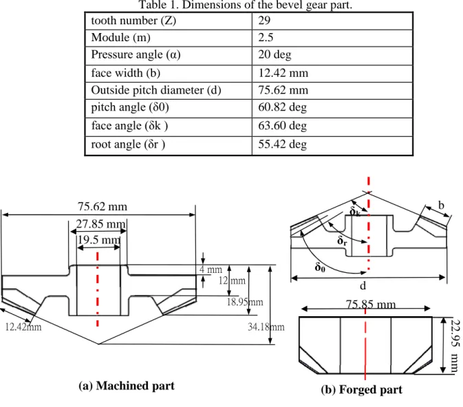
Dimensions of the machined and the forged parts of bevel gear are shown in Fig. 1. The detail data of the bevel gear are listed in Table 1. The proposed forging processes and the algorithms of preform and punch tip surface design are given in the following sections.
Table 1. Dimensions of the bevel gear part.
tooth number (Z) 29
Module (m) 2.5
Pressureangle(α) 20 deg
face width (b) 12.42 mm
Outside pitch diameter (d) 75.62 mm pitch angle(δ0) 60.82 deg faceangle(δk ) 63.60 deg rootangle(δr) 55.42 deg
Fig. 1. The machined and the forged parts
2.1 Forging Process Design
For the conventional forging process, cylindrical (case 1) and chamfered (case 2) billets are adopted for one-step forging, respectively. For the multi-step orbital forging process, preforms are designed using the proposed design algorithm.
2.2 Preform Design Algorithm
A preform design of the orbital forging process is based on the volume constancy and geometrical features of the product to lower the forming load. The volumes of the billet and the forged part were 90,014 and 84,410 cubic mm, respectively. The basic geometry of the preform is a trapezoidal cone with a concave cavity to decrease the forging load and smooth the material
(a) Machined part (b) Forged part
75.62 mm 27.85 mm 19.5 mm 4 mm 12 mm 18.95mm 34.18mm 12.42mm 75.85 mm 2 2 .9 5 m m δ0 δr δk d b
The International Conference on Advances in Materials and Processing Technologies
2-5 November 2008 Manama, kingdom of Barhrain
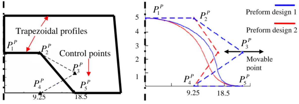
flow. The profile of the concave cavity can be designed with any possible shapes. Three types of cavity profiles, trapezoid, arc, and Bezier curve are proposed in this paper. A fourth-order Bezier curve with five control points is proposed referring to the characteristic points of the machined part. The inner and outer trapezoidal profiles of the preforms and the schematic diagrams of the Bezier curve and the corresponding control points, P1P to P5P , are shown in Fig. 2. The positions of the control points are aligned directly to the trapezoidal inner profile, except the third control point, P3P, which is free to move horizontally to give different curves of cavity designs. The inner profiles of the Bezier curve are controlled by varying the position of the control point P3P(Fig. 2).
Fig 2. Preform designs with cavities of trapezoidal (left) and Bezier curve (right) profiles. The flow chart and the schematic diagrams of the proposed preform design algorithm are shown inFig. 3.The design steps are as follows:
(1) Determine the largest diameter of trapezoid, Ro - the maximum outside diameter of the
forged gear is adopted to contain the largest diameter of preform.
(2) Determine the outer draft angle –the outer draft angle of preform is set to 5 degrees according to the conventional forging die design.
(3) Determine the largest diameter of concave cavity, Ri–the larger diameter of the concave is
calculated from the middle position of point B to the center.
(4) Determine the largest height of concave cavity, Hc - the largest height of the concave is set
to half of the hub height.
(5) Determine the height of preform, Hp–the last dimension of the preform should be able to
satisfy the volume requirement of billet. The draft angle of the inner cavity and the outer profile of preform are set to be parallel.
Once the dimensions of the basic trapezoidal preform have been determined, the arc cavity profile can be determined by calculating the radius of the largest tangent circle. There are two types of Bezier curve cavity preforms proposed setting the horizontal locations of P3Pto align with control point P5Pand on middle of the control points P4Pand P5P(Fig. 2).
2.3 Punch Tip Section Profile Design Algorithm for Orbital Forging
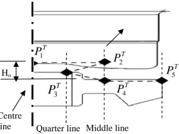
The section profile of punch tip for orbital forging is designed using a Bezier curve which is based on the feature points of machined part as depicted in Fig. 4. The proposed algorithm of the control point location determination of the Bezier curve profile is detailed as follows:
18.5 9.25 Trapezoidal profiles Control points P P5 P P4 P P2 P P1 P P3 Preform design 2 Preform design 1 2 1 3 4 5 18.5 9.25 Movable point P P5 P P2 P P1 P P3 P P4
The International Conference on Advances in Materials and Processing Technologies
2-5 November 2008 Manama, kingdom of Barhrain
Fig 3. Flow chart (right) and schematic diagrams (left) of the proposed preform design algorithm.
(1) Determine the start and the end points, P1Tand P5T - P1T locates at the centre line with a vertical distance, Ho, equal to the height of hub top face with respect to the flange face of
the machined part; P5T locates at the flange face of the machined part with a horizontal distance equal to the maximum outside diameter of the forged part.
(2) Determine two reference lines, the quarter and middle lines –the middle line is located at the half position of the start and the end points; the quarter line is located at the half position of the centre and the middle lines.
(3) Determine the Y (vertical) positions of the control pointsP2T ,P3Tand P4T –the vertical positions of control points P2T are same as control points P1T and P5T ,respectively; Y position of P3Tis located at the half of control pointsP2T and P4T .
(4) Determine the X (horizontal) positions of the control points, P2T ,P3T and P4T - the X positions of these points are aligned with the quarter or middle lines and determined by using Taguchi optimization method.
Fig. 4. The control points of the Bezier curve for punch tip section profile design axisymmetric machined part
Ro H Maximum Ri Maximum Ro Cavity Height Hc 5o
Step 1. Determine Ro(outer radius)
Step 3. Determine Ri = Ro/2(inner radius)
Step 4. Determine Hc= H/2 (cavity height)
Step 5.Determine Hp(preform height)
Trapezoid cavity profile
arc cavity profile
Hp
Hp
Step 2. Determine draft angle
Quarter line Middle line
T P5 T P2 T P4 T
P
3 T P1 Ho Centre lineThe International Conference on Advances in Materials and Processing Technologies
2-5 November 2008 Manama, kingdom of Barhrain
A general n-order Bezier curve p(u) with control points, pi, is expressed in equation 1. The fourth-order Bezier curve with five control points are adopted for punch and preform designs.
n i i iB u P u P 0 ) ( ) ( ;u
0
,
1
,
0
i
n
(1)where Bi,nis a Bernstein polynomial defined by
i n i n i
u
u
i
n
U
B
(
1
)
)
(
, ;)!
(
!
!
i
n
i
n
i
n
(2) The final form of the fourth-order Bezier curve is given by4 4 3 3 2 2 2 1 3 0 4 ) 1 ( 4 ) 1 ( 6 ) 1 ( 4 ) 1 ( ) (u u p u u p u u p u u p u p p (3)
2.4 Optimisation of Punch Tip Section Profile Using Taguchi Method
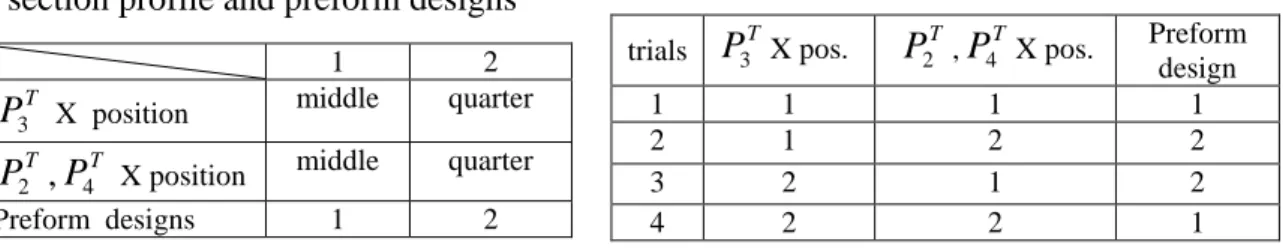
In order to obtain the optimum section profile design described by the control points of a Bezier curve, the Taguchi method is adopted using the L4(23) orthogonal array(OA) to setup the
design combinations. The normalized forming loads and unfilled distance are combined into a single quality index with weighting value 0.5. The preform and punch tip section profile designs are optimised via the DOE method. The DOE optimisation criterion is smaller-the-better to lower the forming load and decrease the unfilled distance. The design factors and the combination of levels are listed in Table 2 and Table 3, respectively. The MSD (mean square deviation) and the SN (signal to noise) ratio of the smaller-the-better are calculated by
y y y
SN MSD nMSD 1 12 22 .... n2 , 10log (4)
2.5 FEM Simulations for Design Evaluation
The DEFORM 3D software is adopted to simulate the conventional and orbital forging processes with the mesh model shown inFig. 5. The flow stress model of AISI4120 at 600℃ is given by520.450.1296MPa using the tensile tests. The parameters of the CAE simulations for the conventional and orbital forging are listed inTable 4.
Fig. 5. CAE models of the conventional and the orbital forging simulations.
1 2
T
P3 X position middle quarter
T
P2 ,P4T X position middle quarter
Preform designs 1 2
trials P3TX pos. P2T,P4T X pos. Preform design
1 1 1 1
2 1 2 2
3 2 1 2
4 2 2 1
Table 2. Design factors of punch tip section profile and preform designs
Table 3. L4(23) OA of Taguchi method
Mesh number:107495 Mesh Size:1 ~ 1.72 mm Mesh number:92501 Mesh Size:1.14 ~1.81 mm Mesh number:92501 Mesh Size:1.14 ~1.81 mm Mesh number:294567 Mesh Size:0.84~1.24 mm
The International Conference on Advances in Materials and Processing Technologies
2-5 November 2008 Manama, kingdom of Barhrain
Table 4. CAE set-ups of conventional and orbital forging simulations
2.6 Experimental Setup
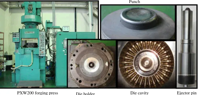
The orbital forging experiments were carried out on a PXW-200press. The equipments of the press and the components of die are shown inFig. 6.Testing conditions of the press were set according to the parameters of the CAE simulation listed in Table 4.
Fig 6. PXW-200 orbital forging press and the installed tools
3. RESULTS AND DISCUSSION
The forging loads, effective stress, damage, and the unfilled distance of the conventional and the orbital forging processes are compared. The cold and warm conventional forging with cylindrical r and chamfered cylindrical billets (case 1 and case 2, respectively) are considered.
Die holder Die cavity Ejector pin
PXW200 forging press
Punch conventional orbital
Workpiece material AISI-4120 AISI-4120
Cold 25℃ Forging Temp. Warm 600℃ 600℃ number 17406 40870 Element Size 2.0~3.5 mm 1.45~2.3 mm velocity 30 mm/s 12.56 rad/s Cold forging 25℃ Top die
Temp. Warm forging 100℃ 100℃
Cold forging 25℃
Bottom die
Temp. Warm forging 100℃
100℃ 1 mm/sec. up
Cold forging 25℃
Ejector
Temp. Warm forging 100℃ 100℃
Cold forging All 0.12 (shear) Friction
condition Warm forging All 0.25 (shear)
Top die 0.18 (coulomb), others 0.25 (constant shear)
The International Conference on Advances in Materials and Processing Technologies
2-5 November 2008 Manama, kingdom of Barhrain
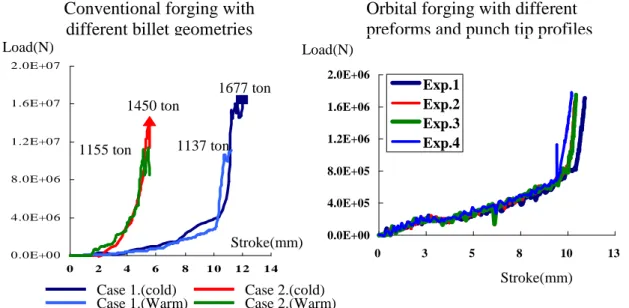
3.1 Forming Loads Comparison of the Conventional and Orbital Forgings
The required forming loads for conventional and orbital forgings are shown in Fig. 7. The maximum cold forging loads of conventional forging with a cylindrical billet (case 1) and a chamfered cylinder (case 2) are 1677tons and 1450 tons, respectively. It demonstrates the chamfered billet requires lower energy due to the billet geometry design. The forging loads can be further lowered using warm forging process; the maximum warm forging loads for case 1 and case 2 are decreased to 1137 tons and 1150 tons, respectively. Only warm forging is considered in the orbital forging processes; the required maximum loads of orbital forgings show no obvious difference for trials 1 to 4 but have much lower values than that of the conventional forgings.
Fig 7. Loads comparison of the conventional and the orbital forging processes. 3.2 Preform and Punch Design Via Taguchi Method
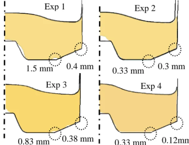
The improvement of die filling is very critical to get a high quality gear forging product. The unfilled gaps are measured at the two locations of a gear tooth section as shown in Fig. 8, and the averaged gap is defined as the unfilled distance. The calculation results of the normalized and weighted quality index for each combination of DOE are listed in Table 5. The best result among the four experiments is case 2 in terms of the quality index which gave smaller unfilled gap and lower forging load. The response chart and ANOVA analysis are shown in Fig. 9 and
Table 6, respectively. The best combination is level 1, 2, and 2 for the locations of control points 3, 2 and 4, and type of preform design, respectively. Since the optimum combination is the experiment 2 in DOE, there is no need to do more confirmation experiments. The ANOVA analysis indicates that locations of the control points are more significant and the preform types less significant. The effects of preform design are not significant because of the property of local control of the Bezier curve. Two types of preform designs are obtained by changing the third control point only and the cavity profiles of Bezier cure are changed slightly (Fig. 2).
The unfilled distances and maximum forging loads of preform designs with the cavity of trapezoid and arc profiles are compared and shown in Fig. 10. Although the punch tip surface section profile is designed with the best combination (Fig. 9), the maximum forging loads and the unfilled gaps of these designs are still larger than the best design with Bezier curve cavity. That means the preform design with Bezier curve cavity is helpful to the die filling improvement.
Orbital forging with different preforms and punch tip profiles
0.0E+00 4.0E+06 8.0E+06 1.2E+07 1.6E+07 2.0E+07 0 2 4 6 8 1 0 12 14
Conventional forging with different billet geometries
1677 ton 1137 ton 1450 ton 1155 ton 0.0E+00 4.0E+05 8.0E+05 1.2E+06 1.6E+06 2.0E+06 0 3 5 8 10 13 Exp.1 Exp.2 Exp.3 Exp.4
Case 1.(cold) Case 2.(cold) Case 1.(Warm) Case 2.(Warm) Load(N)
Stroke(mm)
Load(N)
The International Conference on Advances in Materials and Processing Technologies
2-5 November 2008 Manama, kingdom of Barhrain
Table 6 Results of the ANOVA analysis
Fig .9. Response chart of the L4(23) DOE
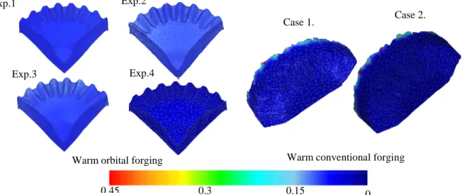
Fig 10. The die filing of the preform design with trapezoid and arc cavity 3.3 Effective Stress and Damage value distributions
The effective stress distributions of the warm orbital and conventional forgings are compared and shown inFig. 11. The stress distribution of experiments 2 and 4 are more uniform and lower than the other experiments, which means the materials are easier to flow and the die filling is better. The lowest maximum stress level of experiment 4 explains the reason of the smallest unfilled gap distance 0.165mm obtained in this try. In the conventional warm forgings, the maximum stress level of case 2 is higher than that of case 1 and the forging load is higher, too.
The distributions of damage values for warm orbital and conventional forgings are compared and shown in Fig. 12. All cases have very low values except the flash areas of conventional forgings. It means that the fracture defects are not likely to happen in the production process.
Preform with trapezoid cavity
Load = 169 ton
Preform with arc cavity
Load = 173 ton 0.76 mm 0.36 mm 1.01 mm
Unfilled gap distance
0.43 mm Unfilled gap distance
Exp. average unfilled gap(mm) Forming Load (Tons) Normalized quality index 1 0.75 171 0.75 2 0.315 167 0.128 3 0.605 175 0.876 4 0.165 173 0.375
Table 5. Results of DOE and quality index
Fig 8. The unfilled gap of the experiments 1.5 mm 0.4 mm Exp 1 0.33 mm 0.3 mm Exp 2 0.83 mm 0.38 mm Exp 3 0.33 mm 0.12mm Exp 4 12 9 6 3 0 1 2 1 2 1 2 T P3 Location T P2 , T P4 Location Preforms factors DOF Seq SS Adj
SS Adj MS F A(P3) 1 28.47 186.6 28.47 1.79 B(P2, P4) 1 128.97 128.97 128.97 8.12 C (Preform)
1 pooled pooled pooled
Result Error
1 15.89 15.89 15.89
The International Conference on Advances in Materials and Processing Technologies
2-5 November 2008 Manama, kingdom of Barhrain
Fig 11. Effective stress distribution of the orbital (left) and conventional (right) forgings.
Fig 12. Damage value distributions of the orbital (left) and the conventional (right) forgings. 3.4 Die Stress Analysis
The tool life is critical for the design of forging process and die geometry. The effective stress distributions of tools are shown inFig. 13to compare the die life of warm orbital with that of the conventional forging process. The maximum tool stress of the orbital forging are smaller than the yield strength of the die material SKD 61(1400 MPa); on the other hand, the maximum die stresses of the conventional warm forging process are much higher than the yield stress of die material and fracturing failure would happen. The hot forging is required for conventional forging process to decrease the forming load and the die stress in stead of the warm forging. 3.5 Experimental Measurement
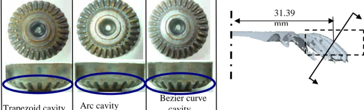
The geometries of forged gear parts were measured using CMM and laser scanner to obtain the thickness, section profile, and tooth surface of the bevel gear. The forged parts and the position of section profile measurement are shown inFig. 14.The forged specimens for different preform designs with three types of inner cavities: trapezoid, arc, and Bezier curve profiles give different filling results. The preform design with Bezier curve cavity has a smoother material flow control and the gear teeth are filled better. The tooth thickness was measured at four different positions along vertical (Y) and horizontal (X) directions at a distance of 31.39mm with respect to the center of gear (Fig. 15). The measured data and averages of the forged parts are
Exp.4 Exp.2 Exp.1 Exp.3 0 0.3 0.45 0.15 Case 1. Case 2.
Warm orbital forging Warm conventional forging
Exp.3 Exp.1 Exp.4 Exp.2 630 456 283 109 Mpa 640 539 439 338 Case 1. with cylindrical billet
Case 2. with chamfered cylindrical billet
The International Conference on Advances in Materials and Processing Technologies
2-5 November 2008 Manama, kingdom of Barhrain
31.39 mm
listed in Table 7. The average tooth thickness of the Bezier curve preform cavity design is the biggest, which means the die filling is better and a better tooth geometry is promised.
Fig 13. Die stress analysis for orbital (experiment 2) and conventional (case 1) forgings.
Fig 14. Forging results using different preform designs and the position of measurement
Fig 15. Tooth measurement positions
Position trapezoid arc Bezier curve
(35,0) 2.44 2.56 2.82 (-35,0) 2.21 2.56 2.77 (0,35) 2.36 2.75 2.86 (0,-35) 2.56 2.88 2.70 Average 2.39 2.68 2.79 -X +X -Y
Table 7. Tooth thickness measurement data +Y 31.39 mm Orbital punch Orbital Die Mpa 1200 800 400 0 Mpa 989 659 330 0 2200 1470 733 0 2350 1670 783 0 MPa MPa Conventional punch Conventional die
Trapezoid cavity Arc cavity
Bezier curve cavity
The International Conference on Advances in Materials and Processing Technologies
2-5 November 2008 Manama, kingdom of Barhrain
The forged part using the preform design with Bezier cavity was scanned for the rebuilding of the forged tooth surfaces. The scanned data cloud and the fitted part surfaces are shown inFig. 16 as well as the measurement results of unfilled distance. The unfilled distances at the ends of the gear tooth are larger than that of the middle position because of the material filling is more difficult at the corner of die cavity. These unfilled areas can be filled at the resizing process.
The gear tooth section profile of experimental tests shown in Fig. 17 is compared with the section cut of the machined part and the CAE predictions, respectively. The maximum deviations with respect to the machined part and the CAE prediction are 0.3 and 0.2 mm, respectively. This comparison validates the die fill cab be predicted by the CAE simulation precisely.
Fig 16. Tooth surface scanning, surface fitting, and unfilled gap measurement
Fig 17. Comparisons of the predicted tooth profile with the CAD (left) and experiment (right) 4. CONCLUSIONS
In this paper, intuitive algorithms of punch tip surface section profile and preform designs are proposed and applied to the bevel gear orbital forging successfully. The CAE and experimental results are compared and a close agreement has been achieved. The summaries of conclusions are as follows,
1. The forging loads of orbital warm forging process are much lower than that of the conventional forging. The forming loads are dramatically decreased from more than one Machined part Machined part Profile of forged part A A B B Forged gear surface
CAE prediction
CAE result
Profile of forged part Forged gear surface
(a)Scanned data cloud
(b) Surface fitting (c) unfilledmeasurement
Measured tooth section Compare with
The International Conference on Advances in Materials and Processing Technologies
2-5 November 2008 Manama, kingdom of Barhrain
thousand tons to less than two hundred tons using the orbital forging instead of the conventional forging.
2. The maximum die stress of conventional forging is twice higher than that of the orbital forging. The warm forging is not likely to be applied to the conventional forging due to the high stress level in the tools. But the orbital forging process is capable of making this product without the concern of die failure since the die stress much smaller than the yield strength of die material. 3. The section profile of punch tip surface designed with Bezier curve is helpful not only to
increase the die filling but also the tool life. A smaller unfilled distance and lower die stress can be obtained with the proposed new punch design methodology.
4. Preform designs with concave cavity are critical to the die filling; the different cavity profiles: trapezoid, arc, and Bezier curve have a significant influence on the die filling.
5. ACKNOWLEDGEMENT
Financial support for this work was provided by the National Science Council Taiwan, R.O.C, under the contract NSC 95-2622-E-151 -016 -CC3. The man power and facility support of the NEW KAILUNG GEAR & MACHINERY CO., LTD. are specially thanked.
6. References
[1] J.H. Song, Y.T. Im, Process design for closed-die forging of bevel gear, J. of Mater. Process. Technol.,vol.1-7 (2007)192-193
[2] J.H. Song, Y.T. Im, Process design for closed-die forging of bevel gear, J. of Mater. Process. Technol.,vol.1-7 (2007)192-193
[3] G. Li, J.T. Jinn, W.T. Wu, S.I. Oh, Recent development and applications of three-dimensional finite element modeling in bulk forming processes, J. of Mater. Process. Technol., 113 (2001) 40-45.
[4] C. Hu, K. Wang, Q. Liu, Study on a new technological scheme for cold forging of spur gears, J. of Mater. Process. Technol., 187-188 (2007) 600-603.
[5] G. Liu, L.B. Zhang, X.L. Hu, Z.R.Wang, R.W. Wang, S.D. Huang, Q.B. Tang, Applications of numerical simulation to the analysis of bulk-forming processes-case studies, J. of Mater. Process. Technol. 150 (2004) 54-61.
[6] J.J. Sheu and C. H. Yu, The Die Failure Prediction and Prevention of the Orbital Forging Process," J. of Mater. Process. Technol., doi : 10.1016/ j. jmatprotec.2007.11.178
[7] J.H. Song, Y.T. Im, Process design for closed-die forging of bevel gear, J. of Mater. Process. Technol.,vol.1-7 (2007)192-193
[8] G. Li, J.T. Jinn, W.T. Wu, S.I. Oh, Recent development and applications of three-dimensional finite element modeling in bulk forming processes, J. of Mater. Process. Technol., 113 (2001) 40-45.
[9] C. Hu, K. Wang, Q. Liu, Study on a new technological scheme for cold forging of spur gears, J. of Mater. Process. Technol., 187-188 (2007) 600-603.
[10] G. Liu, L.B. Zhang, X.L. Hu, Z.R.Wang, R.W. Wang, S.D. Huang, Q.B. Tang, Applications of numerical simulation to the analysis of bulk-forming processes-case studies, J. of Mater. Process. Technol. 150 (2004) 54-61.
Contact info:
J.J.Sheu (Jinn Jong Sheu) Professor;
National Kaohsiung University of Applied Sciences, Department of Mold and Die Engineering, 415 Chin Kung Road,
Kaohsiung 807, Taiwan, R.O.C. TEL:+886-7-3814526 ext5406 Email:[email protected]