insertion loss of⫺1.6 dB, sharp rejection due to two transmission zeros in the passband edge created by interstage coupling, and low group delay varied between 0.2 and 0.5 ns.
ACKNOWLEDGMENT
The authors wish to acknowledge National Nano Device Labora-tories for supporting the equipments and the financial support of this study by the National Science Council of the Republic of China under Grant NSC 94 –2213-E-492– 001.
REFERENCES
1. W. Menzel, L. Zhu, K. Wu, and F. Bo¨gelsack, On the design of novel compact broad-band planar filters, IEEE Trans Microw Theory Tech 51 (2003), 364 –370.
2. C.C. Chen, J.T. Kuo, M. Jiang, and A. Chin, Study of parallel coupled-line microstrip filter in broadband, Microw Opt Technol Lett 48 (2006), 373–375.
3. G.G. Roberto and I.A. Jose´, Design of sharp-rejection and low-loss wide-band planar filters using signal-interference techniques, IEEE Trans Microw Theory Tech 15 (2005), 530 –532.
4. G.L. Matthaei, Interdigital band-pass filters, IEEE Trans Microw The-ory Tech 10 (1962), 479 – 491.
5. D.G. Swanson, Jr, Grounding microstrip lines with via holes, IEEE Trans Microw Theory Tech 40 (1992), 1719 –1721.
6. J.S. Hong and M.J. Lancaster, Development of new microstrip pseudo-interdigital bandpass filters, IEEE Microw Guided Wave Lett 5 (1995), 261–263.
7. M.H. Weng, W.N. Chen, T.H. Huang, C.Y. Hung, and H.W. Wu, Stepped impedance resonator bandpass filters using tapped-line for controlling spurious response, Microw Opt Technol Lett 40 (2004), 481– 484. 8. Federal Communications Commission, Revision of part 15 of the
commission’s rules regarding ultra-wideband transmission systems, Tech Rep ET-Docket FCC 02– 48 (2002), p 12.
9. IEEE P802.15 Working Group for Wireless Personal Area Networks, Detailed DS-UWB simulation results, IEEE 802.15– 04-0483r4 (2004), pp. 11–12.
10. Zeland Software, Inc., IE3D Simulator, 1997.
11. R.Y. Yuan, M.H. Weng, C.Y. Hung, H.J. Chen, and M.P. Houng, Novel microstrip interdigital bandstop filters, IEEE Trans Ultrason Ferroelectrics Freq Control 50 (2004), 1022–1025.
12. C.M. Tsai, S.Y. Lee, and C.C. Tai, Hairpin filters with tunable trans-mission zero, IEEE Microw Theory Tech MTT-S Int Dig 3 (2001), 2175–2178.
© 2006 Wiley Periodicals, Inc.
SINGLE-ENDED FREQUENCY DIVIDER
WITH MODULI OF 256 –271
Sheng-Che Tseng,1Chinchun Meng,1Shao-Yu Li,2Jen-Yi Su,1 and Guo-Wei Huang3
1Department of Communication Engineering
National Chiao Tung University Hsinchu 300
Taiwan, Republic of China
2Department of Electrical Engineering
National Chung-Hsing University Taichung
Taiwan, Republic of China
3National Nanometer Device Laboratories
Hsinchu 300
Taiwan, Republic of China
Received 14 March 2006
ABSTRACT: This paper demonstrates a low-cost 2.4 GHz single-ended
frequency divider with the divide-by-value from 256 to 271 in the
stan-dard 0.35-m 2P4M CMOS technology. This frequency divider is com-posed of a synchronous current mode logic divide-by-4/5 prescaler, an asynchronous true single-phase-clock toggle flip-flops divide-by-64 di-vider, and a digital control circuitry. This proposed divider is single-ended and compatible to the single-single-ended low-phase-noise Colpitts VCO. The operating frequency range of the divider is from 400 to 2.9 GHz. Most of the input sensitivity levels are about⫺10 dBm and the lowest level is⫺25 dBm at 2.4 GHz. Its core power consumption is about 28 mW. The chip size is 1.2⫻ 0.7 mm2. © 2006 Wiley
Period-icals, Inc. Microwave Opt Technol Lett 48: 2096 –2100, 2006; Published online in Wiley InterScience (www.interscience.wiley.com). DOI 10.1002/mop.21876
Key words: prescaler; CMOS; single-ended; current mode logic;
di-vide-by-4/5
1. INTRODUCTION
With the advent of wireless communication, the demand of radio frequency integrated circuits (RFICs) is increasing rapidly. The phase-locked loop (PLL) design is a special topic in the RFICs. PLL provides a stable and accurate signal. A frequency divider plays an important role on the PLL system. The divider can control the output frequency of PLL and also dominates the maximum operating frequency and power consumption of PLL.
A divider often includes a high-speed divide-by-4/5 prescaler. This high-speed prescaler dominates the speed and input sensitiv-ity of a whole divider. Many current mode logic (CML) prescalers [1] and true single-phase-clock (TSPC) prescalers [2, 3] are pro-posed. Because of the effects of charge rearrangement, circuit delay, and the requirement of large voltage swing, TSPC prescal-ers operate difficultly at very high frequencies. However, CML circuits have the advantage over TSPC in terms of speed, and so the CML prescaler is adopted to form a high-speed divide-by-4/5 prescaler in this paper. For the power consumption issue, the low-speed divide-by-64 counter is made up of five TSPC toggle flip-flops (TFFs) [4].
Aparicio and Hajimiri showed that a Colpitts VCO has better impulse sensitivity function and lower phase noise [5]. In addition, in order to obtain low phase noise, the VCO trends to be a single chip. Nevertheless, many commercial single-chip Colpitts VCOs are single-ended and most proposed CML prescalers are driven by a differential signal. Thus, this paper offers a single-to-differential amplifier as the input stage and presents a programmable fre-quency divider with a single-ended input. This divider can be easily connected to the commercial products.
Lowering the cost of production is the biggest issue in indus-trials. CMOS technology has a low cost property. Above all, the standard 0.35-m CMOS process is fabricated by the inexpensive I-line photolithography techniques, and so its cost for designing circuits and masking is very low compared with other advanced CMOS technologies. Besides, CMOS technology is mature for high-frequency applications. In this paper, the programmable fre-quency divider is implemented in a low-cost standard 0.35-m CMOS technology at 2.4 GHz.
2. CIRCUIT DESIGN
The block diagram of this programmable frequency divider is displayed in Figure 1. The frequency divider can be grouped into three parts: a single-ended-input synchronous divide-by-4/5 pres-caler, an asynchronous divide-by-64 counter, and a digital control block. They are described in this section.
2.1 High-Speed Synchronous Divide-by-4/5 Prescaler with a Sin-gle-Ended Input
A high-speed synchronous divide-by-4/5 prescaler is built by source couple logics, which have the properties of high speed and low input sensitivity level. Its architecture is shown in Figure 1 and the prescaler is made of DFFs and NAND gates. Here, a modified D flip-flop merged with NAND gate function is represented in Figure 2 and used in this divide-4/5 prescaler to reduce the prop-agation delay of NAND gates in the conventional prescaler [1].
To form the single-ended input character, a single-to-differen-tial transconductance amplifier is used as an input stage in this prescaler, as shown in Figure 3. This amplifier with a single-ended input has a common-gate-configured transistor, M1, and a
com-mon-source-configured transistor, M3, to generate a differential current signal. Then, two resistors, r3and r4, function as loads to
convert current signals to voltage signals. The common-gate-based transistor, M1, is quicker than the common-source-based transistor, M3. However, the input impedance of M3 is reduced for speed improvement by adding a diode-type transistor, M2. Hence, this
input stage can operate at high frequencies. The differential am-plifier with a single-ended input is not used here and is attributed to its common mode rejection ratio (CMRR) problem.
Figure 3 also describes that its input impedance is easily set to 50⍀ to achieve wideband matching by controlling gm1, gm2, r1,
and r2. Because of the single-ended input and wideband matching characters of the input stage, this prescaler can be easily connected to a commercial Colpitts VCO on a board level. Besides, the input sensitivity of the prescaler will be enhanced based on the good input matching and gain from this input stage.
Figure 1 Programmable divider block diagram
2.2 Asynchronous Divide-by-64 Counter and Digital Control Block
In the design of a low-speed counter, power consumption is prior to speed. Therefore, five TSPC DFFs are used to form an asyn-chronous divide-by-64 counter. The schematic of a TSPC DFF is shown in Figure 4 [4]. The digital control block is designed to choose a module among 256 –271, and a 4-bit (D0, D1, D2, D3)
signal is used to select one of the 16 channels or moduli.
Figure 5 Die microphotographs of (a) the divide-by-4/5 prescaler and (b) the divide-by-256 –271 divider
Figure 6 Spectrum of the output signal of the divide-by-4/5 prescaler with a 2.9 GHz input signal divided by 5
Figure 7 Input sensitivity of the divide-by-4/5 prescaler
Figure 8 Input sensitivity of the divide-by-256 –271 divider Figure 4 Schematic of a true single-phase-clock D flip-flop
3. EXPERIMENTAL RESULTS
Two chips are implemented in standard 0.35-m CMOS technol-ogy, as shown in Figure 5. One is a sub-circuit of the divider, a divide-by-4/5 prescaler, and the other is the whole divide-by-256 – 271 divider. The size of the divide-by-4/5 prescaler is 1.12 ⫻ 0.716 mm2, while the size of the divide-by-256 –271 divider is
1.226⫻ 0.732 mm2. Both chips are on-wafer probed with 6-pin
DC probes, GSG RF probes, and GSGSG RF probes, and fed with sinusoidal signals. Then, the output results are measured by Agi-lent Infiniium 54831B Oscilloscope and E4440A Power Spectrum Analyzer.
3.1 Divide-by-4/5 Prescaler
With 3.3 V supply voltage, the current and power consumption of the core are 4.7 mA and 15.5 mW, respectively. Figure 6
repre-sents the output spectrum of the prescaler with a 2.9 GHz input signal divided by 5, and Figure 7 displays the input sensitivity of the prescaler. The operating frequency range is from 400 to 2.9 GHz. The input sensitivity level at the maximum operating fre-quency, 2.9 GHz, is about 0 dBm. The lowest sensitivity level is about⫺25 dBm at its oscillating frequency, 2.4 GHz. Because of the limited slew rate of the sinusoidal input signals, more power is needed to drive the prescaler at low frequencies, as shown in Figure 7. Thanks to the broadband matching property of our proposed input stage, this prescaler is easily matched to 50 ⍀ without passive components such as inductors and capacitors, and its input return loss is about ⫺11 dB at 2.4 GHz. Under the conditions of 2.2 V supply voltage and 9.8 mW power consump-tion, this prescaler can also function with the maximum operating frequency of 2.4 GHz.
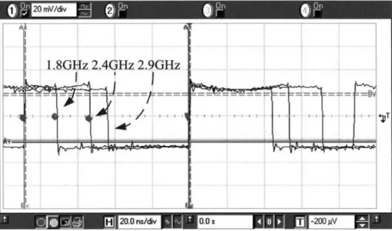
Figure 9 Output waveforms of the divide-by-256 –271 divider with signals divided by 256
3.2 Divide-by-256 –271 Divider
At Vddof 3.3 V, the core current and power consumption are 8.5 mA and 28 mW, respectively. The divide-by-4/5 prescaler of the entire divider dominates the speed, and the additional divide-by-64 counter and digital control block working at low frequencies would not degrade the entire performance. This divider is also able to work from 400 to 2.9 GHz. Its input sensitivity of divide-by-256 and divide-by-271 is shown in Figure 8, and the results of other moduli are similar. With the redesigned input stage, the sensitivity is improved. Figure 9 shows the results of different frequencies (1.8, 2.4, and 2.9 GHz) divided by 256 in time domain, while Figure 10 exhibits the results of various moduli with 2.4 GHz input signals. There are 16 moduli or channels able to select. The peak-to-peak voltage of output waveforms is always the same.
Table 1 represents the comparisons with the former works based on the same technology. Our work has the best sensitivity at 2.4 GHz and the most moduli. While the other CML dividers are differential input, one proposed by us is ended. The single-ended-input divider is easily combined with commercial VCOs on a board level. With the properties of low cost, high-speed opera-tion, excellent sensitivity, and single-ended input, this divider is a good choice to apply to 2.4 GHz wireless communications.
4. CONCLUSIONS
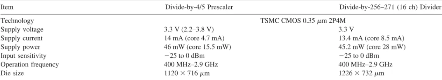
This paper reported a 2.4 GHz low-cost high-speed single-ended-input programmable frequency divider created in standard 0.35-m CMOS technology. With 3.3 V supply, this divider with moduli of 256 –271 can operate from 400 to 2.9 GHz. The average sensitivity level is about⫺10 dBm and the lowest sensitivity is ⫺25 dBm at 2.4 GHz. The power consumption of core is about 28 mW. Its single-ended character and good matching make itself easily connected to commercial single-ended Colpitts VCOs. Ta-ble 2 summarizes the performance of the prescaler and divider.
ACKNOWLEDGMENTS
This work was supported in part by the National Science Council of Republic of China under contract NSC 94 –2752-E-009 – 001-PAE, NSC 94 –2219-E-009 – 014, in part by the Ministry of Eco-nomic Affairs under contract 94-EC-17-A-05-S1– 020, and by the National Chip Implementation Center (CIC).
REFERENCES
1. H.-D. Wohlmuth and D. Kehrer, A 15 GHz 256/257 dual-modulus prescaler in 120 nm CMOS, In: European Solid-State Circuits Confer-ence, Estoril, Portugal, 16 –18 September, 2003. pp. 77– 80.
2. C.-Y. Yang, G.-K. Dehng, J.-M. Hsu, and S.-I. Liu, New dynamic flip-flops for high-speed dual-modulus prescaler, IEEE J Solid-State Circuits 33 (1998), 1568 –1571.
3. J. Navarro and W. Van Noije, A 1.6-GHz dual modulus prescaler using the extended true-single-phase-clock CMOS circuit technique (E-TSPC), IEEE J Solid-State Circuits 34 (1999), 97–102.
4. J. Yuan and C. Svensson, High-speed CMOS circuit technique, IEEE J Solid- State Circuits 24 (1989), 62–70.
5. R. Aparicio and A. Hajimiri, A CMOS differential noise-shifting Col-pitts VCO, In: Proceedings of the International Solid-State Circuits Conference, San Francisco, CA, 3–7 February, 2002. ISSCC Digest of Technical Papers, 2002, vol. 1, pp. 288, 289.
6. R.S. Rana and Z.C. Jian, A 2.4 GHz dual-modulus divide-by-127/128 prescaler in 0.35m CMOS technology, IEEE RFIC Symposium, 2003, Philadelphia, PA, pp. 475– 478.
7. K. Mistry, W. Redman-White, J. Benson, and N. D’Halleweyn, A high speed dual modulus divider in SOI CMOS with stacked current steering phase selection architecture, IEEE RFIC Symposium, 2003, pp. 471– 474. © 2006 Wiley Periodicals, Inc.
INVESTIGATION OF NEW DUAL-MODE
TRIANGULAR-PATCH BANDPASS
FILTERS USING SPUR-LINES
Hai-wen Liu,1Zhi-qun Cheng,1,2and Ling-ling Sun11Microelectronic CAD Center, Hangzhou Dianzi University,
Hangzhou 310018, China
2Department of Electrical and Electronic Engineering
Kong University of Science and Technology Hong Kong
Received 23 March 2006
ABSTRACT: Without any perturbations on the surface of the patch
resonator or orthogonal feed lines, new microstrip dual-mode triangu-lar-patch bandpass filters are presented in this article. The degenerate
TABLE 2 The Performance of the Divide-by-4/5 Prescaler and Divide-by-256 –271 Divider
Item Divide-by-4/5 Prescaler Divide-by-256–271 (16 ch) Divider
Technology TSMC CMOS 0.35m 2P4M
Supply voltage 3.3 V (2.2–3.8 V) 3.3 V
Supply current 14 mA (core 4.7 mA) 13.4 mA (core 8.5 mA)
Supply power 46 mW (core 15.5 mW) 45.2 mW (core 28 mW)
Input sensitivity ⫺25 to 0 dBm ⫺25 to 0 dBm
Operation frequency 400 MHz–2.9 GHz 400 MHz–2.9 GHz
Die size 1120⫻ 716m 1226⫻ 732m
TABLE 1 Comparison with the Former Works in 0.35m CMOS Technology
Refs. fmax(GHz)
a
Power at
fmax(mW) Modulus Type Sensitivity Level
6 2.4 (3) 36 127 High-speed DFFs (divide-by-3/4) 15 dBm at 2.4 GHz
2.5 (3) 128 TSPC (divide-by-32)
7 3 (6.8) 68 64/65 CML ⫺8.6 dBm at 3 GHz
Our work 2.9 (3.3) 28 256–271 CML (divide-by-4/5) ⬃⫺10 dBm (avg.)
TSPC (divide-by-64) ⫺25 dBm at 2.4 GHz
aValues in parentheses are V