Simple 14-Gb/s Short-Range Radio-Over-Fiber
System Employing a Single-Electrode MZM for
60-GHz Wireless Applications
Wen-Jr Jiang, Chun-Ting Lin, Member, IEEE, Anthony Ng’oma, Member, IEEE, Po-Tsung Shih,
Jason (Jyehong) Chen, Michael Sauer, Member, IEEE, Frank Annunziata, and Sien Chi, Fellow, OSA
(Invited Paper)
Abstract—This paper demonstrates the feasibility of a simple
multigigabit-per-second (Gbps) radio-over-fiber (RoF) system employing multilevel orthogonal frequency-division-multiplexing (OFDM) signal modulation at 60 GHz and a single-electrode Mach–Zehnder modulator (MZM). In this paper, the impact of fiber chromatic dispersion and OFDM beat noise on the perfor-mance of the RoF system are investigated by theoretical analysis, VPI WDM-TransmissionMaker simulation and experimental demonstration. A 13.875-Gb/s QPSK OFDM signal occupying the full 7-GHz license-free band at 60 GHz with frequency multipli-cation for the RoF link is demonstrated. After 3 km of standard single-mode fiber transmission with no dispersion compensation, the power penalty is less than 3 dB.
Index Terms—Orthogonal frequency-division multiplexing (OFDM), radio-over-fiber (RoF), 60 GHz.
I. INTRODUCTION
A
S wireless communications continue to enjoy phe-nomenal growth, the ever-rising demand for higher data-speeds coupled with the advent of popular band-width-hungry applications such as high-definition video are putting pressure on wireless communication systems to offer higher data rates. However, data rates of current wireless systems are still limited to several tens of megabit-per-second (Mbps)-hampered by congestion and limited frequency spec-trum in their current frequency bands of operation. Since the key to higher data rates is bandwidth, the most promising pathManuscript received November 01, 2009; revised January 18, 2010; accepted February 04, 2010. Date of publication March 25, 2010; date of current version August 02, 2010. This work was supported by the National Science Council of the Republic of China, Taiwan, under Contract NSC 98-2218-E-009-021, Contract NSC 98-2221-E-155-003-MY3, Contract NSC 98-2221-E-155-004-MY3, and Contract NSC 97-2221-E-009-105-MY3.
W.-J. Jiang, P.-T. Shih, and J. Chen are with the Institute of Electro-Optical engineering and the Department of Photonics, National Chiao Tung University, Hsinchu 300, Taiwan.
C.-T. Lin is with the Institute of Photonic System, National Chiao Tung Uni-versity, Tainan 711, Taiwan (e-mail: [email protected]).
A. Ng’oma, M. Sauer, and F. Annunziata are with the Science and Tech-nology Division, Corning Incorporated, Corning, NY 14831 USA (e-mail: [email protected]).
S. Chi is with the Department of Photonics Engineering, Yuan Ze University, Chung Li 320, Taiwan.
Color versions of one or more of the figures in this paper are available online at http://ieeexplore.ieee.org.
Digital Object Identifier 10.1109/JLT.2010.2045341
to multigigabit-per-second (Gbps) wireless communication is the use of millimeter (mm)-wave frequencies where very large bands of frequency spectrum are available [1]. For instance, the FCC’s 60-GHz band offers 7 GHz of unlicensed spec-trum (57–64 GHz). However, mm-wave wireless networking presents many technical challenges owing to the high carrier frequencies and the wide-channel bandwidths used [2]–[6]. The challenges include the significantly higher air-link loss (about 30 dB higher at 60 GHz than at 2.4 GHz), and reduced device performance and lower power efficiency. In addition, the wide-channel bandwidth means higher noise power and reduced SNR. All these factors make wireless networking at 60-GHz “pico-cellular” in nature with the radio cells typically smaller than 10 m. Consequently, Gbps wireless networking at 60 GHz requires an extensive high-capacity feeder network to interconnect the large number of radio access points.
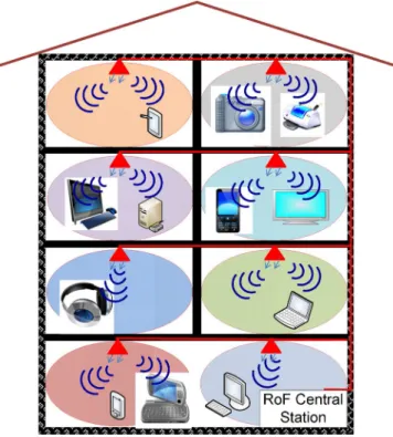
Radio-over-Fiber (RoF) technology can provide the required feeder network as it is best suited to deal with the demands of small-cell networks [7]–[9]. A fiber-based distributed an-tenna system has the special advantage that it can support the transparent distribution of multiple wireless standards or applications. Fig. 1 illustrates a cartoon for future 60-GHz wireless home network based on RoF technology. Because of the high path loss and high attenuation through building walls, in-building radio cells at 60 GHz are confined to a single room. This reduces user interference resulting in very high wireless data capacity per user [10].
In order to achieve multistandard operation, 60-GHz RoF systems must be able to handle wireless signals with different requirements. For instance, for 60-GHz systems, both single-carrier [quadrature amplitude modulation (xQAM)] and multi-carrier [orthogonal frequency-division-multiplexing (OFDM)] modulation formats are important. The two formats may impose different system performance requirements on the 60-GHz RoF systems. For instance, channel uniformity is very critical for single-carrier systems [11], [12]. On the other hand, the pres-ence of multiple carriers in the OFDM signal format makes lin-earity and the ability to handle a high peak-to-average power ratio very critical system parameters. Furthermore, the system requirements are rendered even more critical for the very wide-band ( GHz) channels being considered at 60 GHz and other mm-wave bands. The consequence of these requirements is that they lead to the use of complex RoF system architectures (e.g.,
Fig. 1. Concept of future wireless home network system based on RoF techniques.
dual-electrode modulator structures) for RF OFDM signal trans-mission [13]–[15]. However, it is imperative that the employed RoF links are as simple as possible to reduce cost, while pro-viding the needed performance. This is especially true for cer-tain applications such as in-building systems, where cercer-tain per-formance attributes offered by complex RoF systems are not even required. For example, fiber spans in most in-building ap-plications are typically less than 300 m. Therefore, in-building RoF systems for 60 GHz do not need the fiber chromatic disper-sion tolerance for tens of kilometers that complex systems boast of.
In this paper, we propose a simple RoF system architecture for transporting and generating wideband OFDM signals at 60 GHz and investigate its performance theoretically and experimentally. The RoF system uses only one single-elec-trode Mach–Zehnder modulator (MZM) having no more than 35.5-GHz bandwidth. We experimentally demonstrate the suc-cessful use of the simple RoF system to deliver a 13.875-Gb/s wireless signal at 60 GHz. The OFDM signal occupied the full 7-GHz spectrum at the 60-GHz band and used QPSK modulation. Remote frequency upconversion from the IF to 60 GHz was achieved by employing a system configuration that used a 35.5-GHz local oscillator (LO) signal, which was trans-ported alongside the OFDM signal. This enabled high-quality signal transmission over extended fiber lengths exceeding 3 km without any fiber dispersion compensation. The RoF link included a wireless transmission distance of 3 m.
This paper is organized as follows. Section II describes the concept of the proposed system and the two main design is-sues of the RoF link, namely RF fading and beat noise inter-ference. Section III presents in detailed the theoretical basis of the proposed RoF system using a theoretical model and VPI
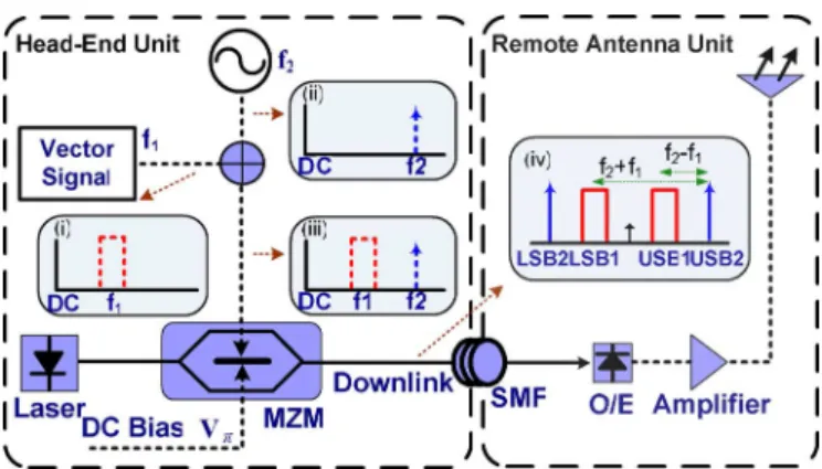
quency of the LO signal is half the desired mm-wave fre-quency of operation. To achieve the double sideband (DSB) with carrier suppression modulation scheme, the MZM is biased at the null point to suppress the optical carrier. Fig. 2(inset iv) shows the generated optical OFDM and LO spectrum that has two upper wavelength sidebands (USB1, USB2) and two lower wavelength sidebands (LSB1, LSB2) with carrier suppression at the output of the MZM. After square-law photo detection, the generated photocurrent can be written as
(1) Expanding the aforementioned equation produces the following terms:
(2) (3) (4) (5)
The beating terms of and
gen-erate the desired OFDM-modulated electrical signals at the sum frequency . The beating terms of and generate electrical OFDM signals at the fre-quency difference , which are well below the desired mm-wave frequency band and are filtered off prior to wireless transmission. Notably, a frequency multiplication factor of two (2) can be achieved by properly choosing frequencies and . This reduces the bandwidth requirements of the RoF trans-mitter allowing for the use of low-frequency electrical and op-tical components, including the MZM ( GHz), which are readily available and have very good performance (e.g., flat fre-quency response).
In this paper, the target sum frequency is 60 GHz. Two main issues will be crucial to the system performance and will be explained in details in following sections. First, the RF fading issue, as shown in (12), comes from the interaction between the two copies of the desired signals, which are generated at the
photodiode, namely, and ,
re-spectively. After fiber transmission, the relative phase between the two generated RF signals will change with transmitted dis-tance owing to the slight difference in the propagation speeds of the two sideband pairs induced by fiber chromatic dispersion. As the relative phase reaches 180 , the electrical RF signal will vanish. This is the RF fading problem. The second issue comes
Fig. 2. Proposed RoF system based on a single-electrode MZM.
from beat noise of two OFDM signals . If the center frequency of OFDM signals is not properly chosen, the beat noise will fall into the signal band and severely degrade the system performance.
III. THEORETICALANALYSIS ANDDESIGNISSUES
A. MM-Wave Signal Generation Based on the Proposed System
In this section, we present a theoretical basis of the proposed mm-wave generation and transmission system. The concept be-hind the generation of the 60-GHz wireless signal is shown in Fig. 2, where only one single-electrode MZM is utilized. The optical field at the input of the single-electrode MZM is given by , where and are the amplitude and angular frequency of the optical field, respectively. The driving RF signal consisting of two sinusoidal signals at different
frequencies MZM is , where
and are the signal amplitudes at frequency and , re-spectively. To simplify the analysis, the power splitting ratio of the MZM is set as 0.5. In order to suppress the undesired optical carrier, the single-electrode MZM is biased at the null point. The optical field at the output of the MZM is then given by
(6) Using Bessel function expansion, the output optical field at the output of the MZM can be rewritten as
(7) where and are the modulation indexes defined as and , respectively. is the -order Bessel function of the first kind. For a small modulation index
Fig. 3. Magnitude of Bessel functions versus different RF modulation index.
the magnitude of Bessel function of the first kind is propor-tional to the order of the function. As shown in Fig. 3, when the modulation index is small, the output optical field can be further simplified to
(8) After square-law photo detection the photocurrent of the mm-wave at frequency of can be expressed as
(9) where is the responsivity of photodiode.
B. Dispersion Induce RF Fading Analysis and Beat Noise
When optical RF signals are transmitted over a standard single-mode fiber with dispersion, a phase shift to each optical sideband relative to optical carrier is induced by fiber disper-sion. The propagation constant of fiber can be expressed as [16]
(10)
where is the derivative of the
propagation constant evaluated at . To simplify the analysis, the effect of high-order fiber dispersion (i.e., third order and higher) at 1550-nm band is neglected. For carrier tones with central frequency at , we have and , where is light speed in free space, is the chromatic dispersion parameter, and is the frequency of the optical carrier. For a standard single-mode fiber, is 17 ps/(nm km). Therefore, after transmission over a standard single-mode fiber of length , the electrical field can be written as
Fig. 4. Simulated RF power of the generated mm-wave signal versus standard single-mode fiber length for various input frequency differences (i.e.,f 0 f ).
After square-law photo detection, the photocurrent at the fre-quency of can be expressed as
(12) Due to fiber dispersion effect, the RF fading issue would be observed. The RF signal power is related to . Therefore, the RF fading issue would become serious when the magnitude of sum frequency
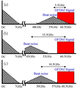
and frequency difference become large. For 60-GHz applications, the sum frequency is fixed at 60.5 GHz, and the frequency difference will dictate the performance of RF fading. As shown in Fig. 4, when the fre-quency difference increases, the RF power will drop off rapidly. For frequency differences of 10 and 40 GHz, the first deep ap-pears following 6 and 1.6-km fiber transmission, respectively. Not only does the smaller frequency difference result in a longer fiber transmission distance, but it also reduces the bandwidth requirements of the transmitter. However, the drawback of a small frequency difference is the risk of having beat noise in-terference. For example, if we choose 5.5 GHz as the frequency difference and set the input frequencies at 33 GHz and 27.5 GHz, then with 7-GHz signal bandwidth, the gener-ated signal will occupy frequencies from 24 to 31 GHz. As a re-sult, the beat noise (i.e., ) will fill the band from 48 to 62 GHz. Since the generated OFDM signal will fill the band from 57 to 64 GHz, the beat noise will fall in-band, as shown in Fig. 5(a), resulting in the possibility for severe system perfor-mance degradation. It is therefore necessary to choose proper frequencies of the input signals in the design process in order to avoid beat-noise induced system performance degradation. A good example is shown in Fig. 5(b), where a frequency dif-ference of 15.5 GHz is chosen, resulting in the beat noise occu-pying the band from 38 to 52 GHz and causing no interference. Therefore, there are tradeoffs between RF fading and beat noise interference. In the following analysis, we will choose the lowest possible frequency difference without causing any beat noise interference. With a target signal bandwidth of 7 GHz and center frequency of 60.5 GHz, we have
GHz
GHz (13)
Fig. 5. Beat noise interference in the proposed system and how to keep it from degrading system performance: (a) beat signal falls inside the desired band, (b) beat signal is far away from desired band, and (c) beat noise is just outside the desired frequency band.
This leads to a frequency difference equal to 10.5 GHz and input signal frequencies GHz and GHz, respectively. In this case, the beat noise falls just outside the desired signal band, as shown in Fig. 5(c). With the chosen frequency parameters, we can calculate the RF fading perfor-mance. Fig. 6(a) shows the RF power of the mm-wave signals generated between 57 and 64 GHz plotted against frequency. The line and circle represent theoretical results obtained using the model in (12) and VPI WDM-TransmissionMaker simula-tion results, respectively. It can be seen that RF fading is neg-ligible over the whole 7-GHz spectrum for fiber spans up to 1 km. Beyond 1 km, frequencies in the lower part of the spec-trum begin to experience increasing attenuation because they are generated from larger frequency differences. After 4 km of fiber transmission, the attenuation increases to 14 dB at 57 GHz and only 3 dB at 64 GHz. Nonetheless, for typical indoor appli-cations, 2–3 km is more than enough [17]. On the other hand, if longer fiber transmission distances are needed, then any one of the four optical sidebands (see Fig. 2) may be filtered off to eliminate fading. To compare the fading length of the pro-posed system to that of a DSB intensity-modulation direct-de-tection (IMDD) transmission system, we plot the calculated and the simulated (VPI WDM-TransmissionMaker) fading (signal power) as a function of frequency. As Fig. 6(b) shows, the first deep (total fading) at 60.5 GHz occurs after just 1 km of standard single-mode fiber transmission in the case of the DSB IMDD RoF system. Therefore, compared with the DSB IMDD RoF system, the proposed system offers superior transmission per-formance and more flexible system design.
Fig. 6. Simulations results of RF fading at 60 GHZ band versus different trans-mission length, (a) proposed system, (b) DSB modulation format.
IV. EXPERIMENTALRESULTS
A. Experimental Setup
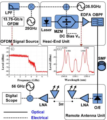
Fig. 7 depicts the experimental setup of the RoF system [18]. Due to the bandwidth limitation of the arbitrary waveform gen-erator (AWG) located at the head-end unit (HEU), a 3.5-GHz-wide OFDM signal was generated using a Matlab Program. The OFDM signal had 37 subcarriers, as shown in Fig. 7(inset i). It was then upconvert to 25 GHz using an electrical mixer. Both sidebands of the up-converted OFDM signal were retained for transmission in order to emulate a 7-GHz-wide OFDM signal. Since the OFDM subcarriers were transmitted independently (uncorrelated) and demodulated independently at the receiver, the total bit rate of the 7-GHz-wide OFDM signal was double that of the baseband OFDM signal generated by the AWG. The resolution of the digital-to-analog converter (DAC) of the AWG was set to 8 bits. The DAC sampling rate was 24 GSample/s. The inverse fast Fourier transform (FFT) length was 256, resulting in a subcarrier symbol rate of 93.75 MSymbol/s. Therefore, with a total of 74 subcarriers and QPSK modulation on each subcarrier, the combined data rate of the 7-GHz-wide OFDM signal at the output of the electrical mixer was 13.875 Gb/s. The signal was then combined with a 35.5-GHz LO signal gen-erated by a signal generator. The composite signal was then used to drive a single-electrode MZM specified for 40-Gb/s data transmission with 0-dBm driving power. The optical signal source was a DFB laser, emitting -dBm optical power at 1550-nm wavelength. The continuous wave optical signal was fed into the MZM, where it was modulated by the com-bined OFDM and LO signals. The MZM modulator was biased
Fig. 7. Experimental setup of the proposed RoF system (LPF: low-pass filter; OBPF: optical BPF).
at the point of minimum transmission in order to suppress the optical carrier. Therefore, the optical signal exiting the MZM comprised a total of four sidebands, two unmodulated subcar-riers at 35.5 GHz and two OFDM-modulated subcarriers at 25 GHz, where is the optical carrier frequency, as shown in Fig. 7(inset ii).
One of the advantages of the proposed system is that the rel-ative intensity between the unmodulated optical subcarrier and the OFDM-modulated subcarrier can be tuned easily by inde-pendently adjusting the amplitudes of the two input signals (RF) to optimize system performance. The optical signal was then amplified by an erbium-doped fiber amplifier (EDFA) with a noise figure of 4 dB. After the EDFA, an optical bandpass filter (BPF) with a 3-dB bandwidth of 3 nm was used to suppress the amplified spontaneous emission (ASE) noise. The optical signal was then transmitted to a remote antenna unit (RAU) connected by standard single-mode fibers of different lengths. At the RAU, the OFDM signal at 25 GHz was upconverted to 60.5 GHz through square-law photo-detection (mixing with the remotely transmitted 35.5-GHz LO signal) in the 67-GHz photodiode. The generated electrical power is 39.3 dBm with -dBm receiving optical power. Therefore, the E/O and O/E conversion loss of the proposed RoF link was about 39.3 dB. Since the OFDM signal at 25 GHz was 7-GHz wide, the signal generated at the RAU was also 7-GHz wide, occupying the full spectrum at the 60-GHz band specified by the FCC (57–64 GHz). The OFDM signal was then amplified by a LNA with 38-dB gain, and the power of the amplified OFDM signal was 1.3 dBm. After the LNA, the 60-GHz OFDM signal was in one case immediately downconverted to an IF without transmission over the air. In the second case, the amplified signal was fed into a rectangular waveguide-based standard gain horn antenna
Fig. 8. BER curves of 13.875-Gb/s QPSK OFDM signal after transmission over the RoF system including 3-m wireless distance.
with about 23-dBi gain and transmitted over 3-m wireless dis-tance. After transmission over the air, the 60-GHz signal was re-ceived by another standard gain horn antenna with dBm received power. Therefore, the estimated path loss of the wire-less transmission is about 77.8 dB. Then, the received signals was amplified with an LNA ( 21 dB) and passed on to the 60-GHz downconverter. The 60-GHz downconverter consisted of a mixer driven by a 56-GHz LO, as shown in Fig. 7. There-fore, the received OFDM signal at 60.5 GHz was down-con-verted to an IF of 4.5 GHz. The IF was chosen so as to maintain the 7-GHz-wide spectrum of the received OFDM signal. The waveforms of the downconverted OFDM signals were captured by a real-time oscilloscope with a 40-GSample/s sampling rate and a 3-dB bandwidth of 13 GHz for offline signal processing and analysis. An offline Matlab digital signal processing pro-gram was employed to demodulate the OFDM signal. The de-modulation process included synchronization, FFT calculation, and one-tap equalization.
B. Experimental Results and Discussions
First, we measured the performance of the system with 3-m wireless transmission. Fig. 8 shows the bit-error-rate (BER) curves for the received 13.875-Gb/s QPSK OFDM signal. The BER was estimated from the measured error vector magnitude (EVM), which is defined in [19] and [20] as
(14) where and are the ideal and the measured con-stellation points, respectively. For QPSK signal, the BER is re-lated to EVM by
(15) where is the Gaussian coerror function. Fig. 8 shows that as fiber transmission length increased, the system sensitivity de-creased. For back-to-back (BTB), 500-m and 1-km transmission
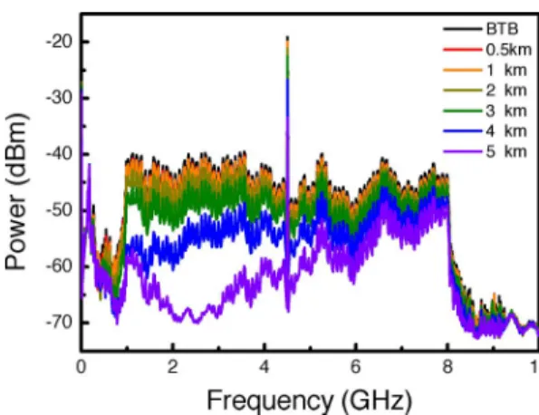
Fig. 9. Downconvert electrical spectrums for different standard single-mode fiber transmission length.
distances, the sensitivity was the same and equals to dBm for a BER of . After 2 km and 3 km of fiber trans-mission, there was a small penalty of about 1 dB and 1.5 dB, respectively, at the BER of . However, after 5 km of fiber transmission, the signal was severely corrupted with the BER greater than . Fig. 9 shows the electrical spec-trum of the down-converted OFDM signal. It can be seen from the figure that the spectrum of the downconverted OFDM signal was 7-GHz wide. The spectrum also shows a peak at 4.5 GHz, which is the residual signal from the 25-GHz LO used to upcon-vert the baseband OFDM signal to 25 GHz back at the HEU. The progression of the chromatic-dispersion-induced fading as the fiber transmission distance becomes larger can also be seen in Fig. 9. It was observed that lower frequency components faded quicker and deeper, just as predicted by the theoretical analysis presented in Section III-B. The reason for the quicker/greater fading at the lower frequency components is because the lower frequency components are generated by larger frequency dif-ferences of the two electrical input signals at the HEU. Fig. 10 shows the constellation diagrams of the demodulated OFDM signals for different fiber transmission lengths with the wire-less transmission distance fixed at 3 m. Very clear constella-tion diagrams were observed until the fiber length exceeded 3 km. The total data rate of the signal was 13.875 Gb/s. The detected optical power corresponding to the constellation dia-grams was dBm. For the BTB case, the calculated EVM was 17.7%. However, lower EVM values up to 16% were ob-tained at higher received optical powers. The clean constellation diagram in Fig. 10 confirms the excellent performance of the RoF system in generating and transmitting high-quality wide-band OFDM signals at 60 GHz both over optical fiber and wire-less distance. It also shows the potential of the system for oper-ating at a bit rate higher than 13.875 Gb/s by using modulation formats of higher order than QPSK (e.g., 8 QAM).
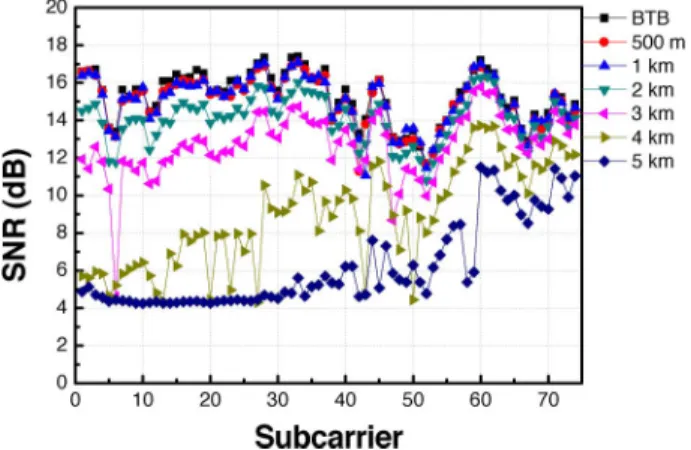
To further investigate the impact of RF fading on signal quality, the SNR of each of the 74 subcarriers making up the OFDM signal was calculated for different fiber transmission distances, using [19]
Fig. 10. Constellations of QPSK OFDM signals: (a) BTB, (b) 500 m, (c) 1 km, (d) 2 km, (e) 3 km, (f) 4 km, and (g) 5 km.
Fig. 11. SNR versus different subcarrier for different standard single-mode fiber transmission length.
The result is shown in Fig. 11. The higher subcarrier number corresponds to higher subcarrier frequency (i.e., subcarrier number 74 is around 64 GHz before downconversion). It was observed that the SNR of the individual subcarriers remained the same for BTB, 0.5 and 1 km of fiber transmission distances. However, for fiber spans longer than 1 km, a drop in the SNR of
the subcarriers at the lower end of the spectrum was observed. For example, after 3 km of fiber transmission, the SNR of the first and the 74th subcarriers dropped by 4 and 1 dB, respec-tively, with respect to their respective BTB SNRs. This result is consistent with the theoretical analysis presented in Section III, which showed that subcarriers at the lower frequencies suffered worse RF fading leading to a reduced average SNR.
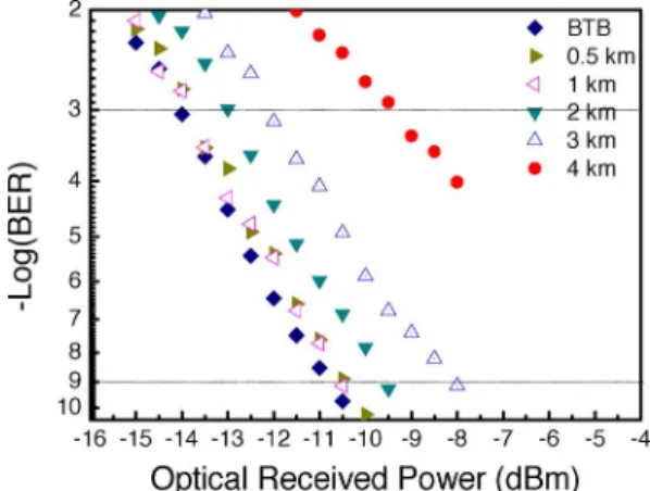
To investigate the performance of the RoF system without wireless transmission, the OFDM signal generated at the RAU was immediately downconverted to the same IF frequency as before (i.e., 4.5 GHz). Just like before, the optical signal was transmitted over different lengths of standard single-mode fiber. The result is given in Fig. 12, where the estimated BER is plotted against the optical signal power. Once again, the performance of the RoF system with BTB, 500 m and 1 km of fiber transmis-sion remained the same. This means that, just like in the case with wireless transmission, the system suffered no penalty due to fiber chromatic dispersion up to 1-km fiber transmission. For fiber transmission distances of 2 and 3 km, there was a penalty of 1 and 1.5 dB, respectively, at a BERs equal to . A larger penalty was observed after transmission over 4 km of standard single-mode fiber. These results are similar to the ones obtained in the case of the system with wireless transmission
Fig. 12. BER curves of 13.875-Gb/s QPSK OFDM signal without wireless transmission.
discussed earlier. The difference in the sensitivities of the two systems (with and without wireless transmission, i.e., Figs. 8 and 12, respectively) is about 1 dB. This is attributed to the pres-ence of an extra LNA required in the wireless receiver (i.e., in the case of the system with wireless transmission).
Given the small dispersion penalty observed for fiber spans up to 3 km, the proposed RoF system is well suited to system ap-plications characterized by short fiber spans, but where minimal system complexity is critical. A good example is in-building applications, where in most instances fiber spans of less than 300 m are sufficient. However, if required, the fading-limited maximum fiber transmission distance may be extended by, e.g., using a filter such as a wavelength interleaver to remove any one of the four sidebands (LO or OFDM) from the modulated optical signal at the HEU prior to transmission. Filtering one of the sidebands results in the generation of only one copy of the desired mm-wave signal at the RAU, eliminating the possi-bility for fading. However, the addition of the filter makes the RoF system more complex, which as stated earlier should be avoided in short-range RoF applications.
V. CONCLUSION
We have theoretically and experimentally investigated the performance of a simple RoF system for transporting and gener-ating multi-Gbps OFDM-modulated wideband wireless signals at 60 GHz. The RoF system employs a single-electrode MZM and uses no linearization techniques. Theoretical analysis of the proposed system shows that by choosing appropriate input signal frequencies, the system can achieve fiber transmission distances exceeding 3 km without any chromatic dispersion compensation. The theoretical analysis was confirmed by experimental results. The RoF system was successfully used to transport a 14-Gb/s OFDM-QPSK-modulated signal at 60 GHz over 3 km of standard single-mode fiber and 3-m wireless distance. Experimental results showed that after 3 km of fiber transmission there was only a small optical power penalty of 2 dB or less, at both BERs of and . Fiber links of 3 km are sufficient for most short-range RoF applications such as in-building systems, where low system complexity is very critical. However, if needed, the RF fading limit of the proposed system may be extended to much longer fiber spans by filtering.
and ZigBee,” IEEE Wireless Commun., vol. 14, no. 4, pp. 70–78, Aug. 2007.
[6] P. Smulders, “Exploiting the 60 GHZ band for local wireless multi-media access: Prospects and future directions,” IEEE Comm. Magn., vol. 40, no. 1, pp. 140–146, Jan. 2002.
[7] M. Sauer, A. Kobyakov, and J. George, “Radio over fiber for picocel-lular network architectures,” J. Lightw. Technol., vol. 25, no. 11, pp. 3301–3320, Nov. 2007.
[8] J. Yu, Z. Jia, L. Yi, Y. Su, T. Wang, G. K. Chang, and T. Wang, “Op-tical millimeter-wave generation or up-conversion using external mod-ulators,” IEEE Photon. Technol. Lett., vol. 18, no. 1, pp. 265–267, Jan. 1, 2006.
[9] Z. Jia, J. Yu, A. Chowdhury, G. Ellinas, and G. K. Chang, “Simulta-neous generation of independent wired and wireless services using a single modulator in millimeter-wave-band radio-over-fiber systems,”
IEEE Photon. Technol. Lett., vol. 19, no. 20, pp. 1691–1693, Oct. 15,
2007.
[10] A. M. J. Koonen and M. García Larrodé, “Radio-over-MMF tech-niques—Part II: Microwave to millimeter-wave systems,” J. Lightw.
Technol., vol. 26, no. 15, pp. 2396–2408, Aug. 1, 2008.
[11] A. Ng’oma, M. Sauer, F. Annunziata, W. J. Jiang, C. T. Lin, J. Chen, P. T. Shi, and S. Chi, “Simple multi-Gbps 60 GHZ radio-over-fiber links employing optical and electrical data up-conversion and feed-forward equalization,” presented at the Optical Fiber Communication Conf. 2009, San Diego, CA, Mar. , Paper OWF2.
[12] M. Weiß, M. Huchard, A. Stöhr, B. Charbonnier, S. Fedderwitz, and D. S. Jäger, “60 GHZ photonic millimeter-wave link for short- to medi-umrange wireless transmission up to 12.5 Gb/s,” J. Lightw. Technol., vol. 26, no. 15, pp. 2424–2429, Aug. 1, 2008.
[13] C. T. Lin, E. Z. Wong, W. J. Jiang, P. T. Shih, J. Chen, and S. Chi, “28-Gb/s 16- QAM OFDM radio- over- fiber system within 7- GHz license-free band at 60 GHZ employing all-optical up-conversion,” presented at the CLEO 2009, Baltimore, MD, May 2009, Paper CPDA8. [14] P. Lombard, Y. L. Guennec, G. Maury, E. Novakov, and B. Cabon,
“Optical distribution and upconversion of MB-OFDM in ultra-wide-band-over-fiber systems,” J. Lightw. Technol., vol. 27, no. 9, pp. 1072–1078, May 2009.
[15] G. H. Nguyen, B. Cabon, and Y. L. Guennec, “Generation of 60 GHZ MB-OFDM signal-over-fiber by up-conversion using cascaded ex-ternal modulators,” J. Lightw. Technol., vol. 27, no. 11, pp. 1496–1502, Jun. 2009.
[16] G. P. Agrawal, Fiber Optic Communication Systems, 3rd ed. New York: Wiley, 2002.
[17] A. Flatman, “In-premises optical fibre installed base analysis to 2007,” presented at the IEEE 802.3 Gigabit Ethernet Over FDDI-Grade Fiber Study Group, Orlando, FL, USA, 2004.
[18] A. Ng’oma, M. Sauer, F. Annunziata, W. J. Jiang, C. T. Lin, J. Chen, P. T. Shi, and S. Chi, “14 Gbps 60 GHZ RoF link employing a simple system architecture and OFDM modulation,” presented at the IEEE Microwave Photonics 2009 Conf., Valencia, Spain, Oct. .
[19] Agilent 8 Hints for Making and Interpreting EVM Measurements, Ag-ilent Technologies , , May 2005 [Online]. Available: http://cp.litera-ture.agilent.com/litweb/pdf/5989-3144EN.pdf
[20] F. Xiong, Digital Modulation Techniques, 2nd ed. London: Artech House, 2006.
Wen-Jr Jiang received the B.S. degree in electrophysics and M.S. degree in
display from the Institute of Electro-Optical Engineering, National Chiao Tung University (NCTU), Hsinchu, Taiwan, in 2006 and 2008, respectively. He is currently working toward the Ph.D. degree at the Institute of Electro-Optical Engineering, NCTU.
He is also currently with the Department of Photonics, NCTU. His research interests include radio-over-fiber systems, digital signal processing, optical mil-limeter-wave generation, photonic vector signal generation, and hybrid access networks.
Chun-Ting Lin (M’07) received the B.S. and M.S. degrees in material science
and engineering from the National Tsing Huang University, Hsinchu, Taiwan, in 1997 and 2001, respectively, and the Ph.D. degree in electro-optical engineering from the National Chiao Tung University (NCTU), Hsinchu, Taiwan, in 2007.
From 2007 to 2009, he was a Research Associate with the Department of Pho-tonics, NCTU. In 2009, he joined the Faculty of NCTU, where he is currently an Assistant Professor with the Institute of Photonic System. His research in-terests include radio-over-fiber systems, optical millimeter-/subterahertz-wave generation and application, optical data formats, and optoelectronic packages.
Anthony Ng’oma (M’02) received the B.Eng. (with merit) and M.Eng. degrees
in electrical engineering and electronics and telecommunications from the Uni-versity of Zambia, Lusaka, Zambia, and the Professional Doctorate in Engi-neering (P.D.Eng.) degree in information and communication technology and the Ph.D. degree in optical communications from the Eindhoven University of Technology, Eindhoven, The Netherlands, in 2002 and 2005, respectively.
He is currently a Senior Research Scientist with the Science and Technology Division, Corning Inc., Corning, NY. From 2005 to 2007, he was a Postdoc-toral Researcher with the Electro-Optic Communications Group, Eindhoven University of Technology. He was engaged in research on low-cost fiber-optic communication technologies for local-area networks and polymer optical fiber-based fiber-wireless systems for millimeter-wave applications. He is the author or coauthor of more than 50 technical publications and two book chapters in the field of fiber-optic communication. His current research interests include fiber-wireless systems for multi-Gbps wireless communication, access network technologies, and in-home networking.
Dr. Ng’oma is a member of the IEEE Photonics Society, the IEEE Commu-nications Society, and the IEEE Microwave Theory and Techniques Society.
Po-Tsung Shih received the B.S. and M.S. degrees from the Department of
Electrophysics, National Chiao Tung University (NCTU), Hsinchu, Taiwan, in 2004 and 2006, respectively. He is currently working toward the Ph.D. degree in the Institute of Electro-Optical Engineering, NCTU.
He is also currently with the Department of Photonics, NCTU. His research interests are radio-over-fiber system, optical millimeter-wave generation, op-tical data format, and opop-tical access network.
Jason (Jyehong) Chen received the B.S. and M.S. degrees in electrical
engi-neering from the National Taiwan University, Taipei, Taiwan, in 1988 and 1990, respectively, and the Ph.D. degree in electrical engineering and computer sci-ence from the University of Maryland, College Park, in 1998.
In 1998, he was a Senior Engineer with JDSU, Milpitas, CA, where he re-ceived ten U.S. patents in two years. In 2003, he joined the Faculty of National Chiao Tung University, Hsinchu, Taiwan, where he is currently an Associate Professor with the Institute of Electro-Optical Engineering and the Department of Photonics.
Michael Sauer (M’95) received the Dr.-Ing. (Ph.D.) degree in electrical
engi-neering from Dresden University of Technology, Dresden, Germany, in 2000. In 2001, he was a Research Scientist with the Communications Laboratory, Dresden University of Technology, where he was engaged in research on fiber Bragg gratings, generation and fiber-optic transmission of millimeter-wave sig-nals, and architectures of millimeter-wave communications systems. He is cur-rently a Research Associate in the Science and Technology Division, Corning Inc., Corning, NY, where he is responsible for high-speed optical networks and communication research. He is the author or coauthor of more than 70 publi-cations in the area of fiber-optic communication. His research interests include fiber-wireless system design, high-speed fiber-optic transmission systems, dig-ital signal processing techniques and modulation formats for high-data-rate sys-tems, signal conditioning with fiber-based components, optical network archi-tectures, and optical packet switching.
Dr. Sauer is a member of the IEEE Photonics Society and the IEEE Commu-nications Society.
Frank Annunziata received the B.S. degree in electrical technology from the
Rochester Institute of Technology, Rochester, NY, in 1981.
He was engaged in research on optical fiber communications and testing for more than 30 years at Corning Incorporated, where he is currently with the Sci-ence and Technology Division. His research interests include radio-over-fiber technology.
Sien Chi received the B.S.E.E. degree from the National Taiwan University,
Taipei, Taiwan, in 1959, the M.S.E.E. degree from the National Chiao-Tung University, Hsinchu, Taiwan, in 1961, and the Ph.D. degree in electro-physics from the Polytechnic Institute, Brooklyn, NY, in 1971.
From 1971 to 2004, he was a Professor and, from 1998 to 2001, he was the Vice President at the National Chiao-Tung University, where he is currently with the Department of Photonics. His research interests include optical-fiber communications, fast and slow light, passive optical networks, and microwave photonics.
Prof. Chi is a Fellow of the Optical Society of America. He is a Chair Pro-fessor at Yuan-Ze University, Chung Li, Taiwan.