國 立 交 通 大 學
電信工程研究所
博 士 論 文
位元交錯編碼調變合作中繼網路之
效能分析與功率分配
Performance Analysis and Power Allocation
for BICM-Coded Cooperative Relaying
Networks
研 究 生:余倉緯
指導教授:沈文和 博士
王忠炫 博士
位元交錯編碼調變合作中繼網路之
效能分析與功率分配
Performance Analysis and Power Allocation for
BICM-Coded Cooperative Relaying Networks
研 究 生:余倉緯
Student:Tsang-Wei Yu
指導教授:沈文和 博士 Advisor:Dr. Wern-Ho Sheen
王忠炫 博士 Dr. Chung-Hsuan Wang
國立交通大學
電信工程研究所
博 士 論 文
A Dissertation
Submitted to Institute of Communication Engineering
College of Electrical and Computer Engineering
National Chiao Tung University
in Partial Fulfillment of the Requirements
for the Degree of Doctor of Philosophy
in
Communication Engineering
Hsinchu, Taiwan
位元交錯編碼調變合作中繼網路之
效能分析與功率分配
研究生:余倉緯 指導教授:沈文和 博士
王忠炫 博士
國 立 交 通 大 學
電 機 工 程 學 系
摘要
位元交錯編碼調變合作中繼網路(BICM-coded cooperative relaying network)是下世代 無線通訊系統所使用的關鍵技術;它承襲了位元交錯編碼調變(bit-interleaved coded modu-lation, BICM)的頻寬與功率的高使用效率,並得益於合作式傳輸的使用,使得它可以在不 需要實際裝置多天線的前提下,即能達到空間分集(space diversity)的效果。在本論文中, 我們將探討此系統的效能分析與功率分配。 位元交錯編碼調變合作中繼網路的效能分析至今仍尚未有完整的探討,特別是針對選 擇性解碼-轉傳(Selection decode-and-forward,S-DF)技術。S-DF 被認為是一實際的轉傳方 式,因為它在可行的複雜度下,能提供比固定式解碼轉傳(Fixed DF)更好的效能。在現有的 文獻中已有 S-DF 的相關分析結果,但皆僅侷限於無通道編碼的系統,並且皆採用一種以 符元為單位的轉傳策略。在此策略中,各符元是分別地被檢測,而僅有正確的符元才允許 被轉傳。實際上,此策略可能不適用於現今真實的系統上,因為它與循環冗餘校驗(cyclic redundancy check)本身特性有所矛盾,況且又需大量額外的信令耗損(signaling overhead)。 本論文考慮的是一種以封包為單位的轉傳策略;包含了兩種 S-DF 方式:S-DF/RT(S-DF with source retransmission) 與 S-DF/Idle (S-DF with source idle) (依訊源端(source)是否在中繼站
解 碼 失 敗 時重 傳 封 包來 做 區 分 ) 。在 快 速衰 退 (fast-fading) 和 區 塊 衰 退 (block-fading)的 Nakagami-m 通道下,本論文提出了在目的端(destination)的位元錯誤率(bit-error-rate,BER) 分析,並且推導了該網路的分集階數(diversity order),同時,也提供了模擬的結果來證實: 在不同的調變、中繼站數量、及通道狀況下,所提出的分析方法的準確性。
在 功 率 分 配 的 部 分 , 本 論 文 考 慮 了 四 種 的 合 作 中 繼 模 式 : 放 大 - 轉 傳 (amplify-and-forward,AF)、S-DF/RT、S-DF/Idle 與 S-DF/AF,其中 S-DF/AF 代表中繼站在 解碼失敗時,切換成以 AF 的模式進行轉傳。本論文的目標為:根據完美的通道狀態資訊 (channel state information),透過功率分配來最小化目的端的 BER。在 AF 模式中,本論文 提出了一近似的 BER,並證明其為等效通道(equivalent channel)之嚴格遞減函數,因而可將 此等效通道視為成本函數(cost function)來進行最佳化。在 S-DF 模式下,則提出了 PA-ABER 與 PA-MGEC 兩種功率分配的方式。PA-ABER 是採用近似的 BER 做為成本函數,經由證 明得知此成本函數對於 S-DF 下的任一種中繼模式而言,皆是 convex 函數,因此可使用 gradient method 來對其進行最佳化。本論文又提出了 PA-MGEC 來進一步減化計算的複雜 度,它將原本在 PA-ABER 的最佳化問題轉換成了一個 max-min 的問題,然後採用了最小 廣義等效通道 (minimum generalized equivalent channel,MGEC)為其成本函數。對於不同 的 S-DF 模式,我們皆提出了 PA-MGEC 下的特定解法。此外,本論文亦證明了 PA-ABER 與 PA-MGEC 皆可以被應用在解碼-重映射-轉傳(decode-remap-and-forward,DRF)的合作中 繼系統上。其中 DRF 代表中繼站被允許使用與 source 不同的星座映射(constellation mapping) 方式,來得到重映射的好處。本論文提供了數值的結果來證實,所提出的方法在效能上的 確大幅地超越了等增益功率分配(equal gain power allocation)。
Performance Analysis and Power Allocation for
BICM-Coded Cooperative Relaying Networks
Student: Tsang-Wei Yu Advisor: Dr. Wern-Ho Sheen
Dr. Chung-Hsuan Wang
Department of Electrical and Computer Engineering
National Chiao Tung University
Abstract
BICM (bit-interelaved coded modulation)-coded cooperative relaying network is one of the key technologies for the next-generation wireless communication systems. It inherits the bandwidth and power efficiency from BICM and also benefits from cooperative transmission for gaining space diversity yet without using multiple physical antennas. This dissertation investi-gates such a system from the aspects of performance analysis and power allocation.
The performance analysis of BICM-coded cooperative relaying network has not yet been fully explored, especially for selection decode-and-forward (S-DF) which has been regarded as a promising scheme that provides better performance over fixed DF with practical complexities. In fact, existing works are limited to un-coded S-DF with a symbol-by-symbol forwarding strategy, in which each symbol is detected separately, and only the correct symbols are forwarded. Unfor-tunately, this strategy may not be applicable to nowadays real systems due to the limitation of cyclic redundancy check and the requirement of additional signaling overhead. This dissertation is the first work that considers BICM-coded cooperative relaying network with a pack-et-by-packet forwarding strategy. In addition, two types of S-DF modes are investigated: S-DF/RT and S-DF/Idle, depending on whether or not the source re-transmits the packet again
when the relay fails to decode. The analysis of bit-error-rate (BER) at the destination and deriva-tion of the diversity orders of the network are proposed for both fast-fading and block-fading Nakagami-m channels. Simulation results are given to show the effectiveness of our analyses in different modulations, number of relays and channel conditions.
This dissertation also provides a comprehensive investigation on transmit power allocation including 4 relaying modes, namely, amplify-and-forward (AF), S-DF/Idle, S-DF/RT and S-DF/AF in which the relay uses AF upon decoding failure. Based on perfect channel state in-formation, the target is to allocate power to minimize the BER at the destination. To avoid the cumbersome (if not impossible) evaluation of the exact BER and an inefficient exhaustive search of the optimal power, this dissertation provides, for individual modes, a simplified cost function which can be optimized efficiently through existing algorithms. For AF, it is shown that the ap-proximate BER monotonically decreases with the equivalent channel, which is then adopted as the cost function for optimization. For S-DF, two power allocation methods are proposed. The first, called PA-ABER, employs an approximate BER as a cost function, which is then proved to be convex for each relaying mode and then optimized through the gradient method. To further reduce the computation complexity, the second method, called PA-MGEC, first transforms PA-ABER to a max-min problem, and the cost function is named minimum generalized equiva-lent channel (MGEC) which can be optimized with existing algorithms for the 3 relaying schemes. Furthermore, this dissertation shows that these two methods are applicable to the net-work with decode-remap-and-forward (DRF) relays, which are allowed to choose different con-stellation mappings from that of source so as to obtain a remapping gain. Numerical results show that both of the proposed methods outperform the equal gain power allocation by large margins with or without remapping.
Acknowledgement
Foremost, I would like to express my sincere gratitude to my advisors, Prof. Wern-Ho Sheen. Thanks for teaching the right attitude on research, for helping me discover and deal with research problems, for patiently discussing with me again and again on details, and for reading and revising my draft papers, for supporting me throughout my Ph.D. studies. I could not have completed my Ph.D. degrees without their advice, guidance and valuable comments.
Second, I would like to express my heartfelt gratitude to Prof. Chung-Hsuan Wang, for giving valuable suggestions, and for instructing and helping me a lot in academic writing.
I would also like to thank my former student colleague Liang-Wei Huang for leading me to the start of my research, Shiang-Jiun Lin for encouraging me when I feel upset. Special thanks to all the student colleagues of Broadband Radio Access Systems Lab (BRASLAB) for their kind help in many aspects.
Finally, I am deeply indebted to my family who have supported me materially and mentally through this long journey.
Contents
Abstract ... iii Acknowledgement ... i Contents ... ii List of Figures ... v List of Tables ... x Notations ... i Chapter 1 ... 1 1.1 Cooperative Relaying ... 2 1.2 BICM ... 3 1.3 Performance Analysis... 5 1.4 Power Allocations ... 61.5 Dissertation Outline and Contributions ... 7
2.1 Network Model ... 10
2.2 Bit-interleaved Coded Modulation (BICM) ... 12
2.3 Signals in Phase-II for different Relaying Schemes ... 14
2.3.1 Amplify-and-Forward (AF) ... 14
2.3.2 S-DF with Source Re-transmission (S-DF/RT)... 14
2.3.3 S-DF with Source Idle (S-DF/Idle) ... 15
2.4 General Form and Decoding at Destination ... 16 3.1 BER Analysis ... 18 3.1.1 S-DF/RT ... 19 3.1.2 S-DF/Idle ... 25 3.2 Diversity Analysis ... 25 3.2.1 S-DF/RT ... 26 3.2.2 S-DF/Idle ... 30 3.3 Numerical Results ... 31 3.4 Summary ... 38 4.1 BER Analysis ... 39 4.1.1 S-DF/RT ... 40 4.1.2 S-DF/Idle ... 43 4.2 Diversity Analysis ... 44 4.2.1 S-DF/RT ... 45 4.2.2 S-DF/Idle ... 49 4.3 Numerical Results ... 50 4.4 Summary ... 57
5.1 Power Allocation for AF Relaying: PA-EC ... 59
5.2 Power Allocation for S-DF Relayings ... 62
5.2.1 PA-ABER ... 62 S-DF/RT and S-DF/Idle ... 65 S-DF/AF ... 65 5.2.2 PA-MGEC ... 66 S-DF/RT and S-DF/Idle ... 67 S-DF/AF ... 68
5.3 Power Allocation Examples ... 69
5.3.1 PA-EC on AF ... 70
5.3.3 PA-MGEC on S-DF/Idle ... 74 5.3.4 PA-MGEC on S-DF/AF ... 76 5.4 Numerical Results ... 77 5.5 Summary ... 97 6.1 PA-ABER ... 100 6.2 PA-MGEC ... 107
6.3 Power Allocation Example ... 108
6.3.1 PA-MGEC on S-DRF/RT ... 108 6.3.2 PA-MGEC on S-DRF/Idle ... 110 6.3.3 PA-MGEC on S-DRF/AF... 112 6.4 Numerical Results ... 114 6.5 Summary ... 125 Appendixes ... 128
Appendix A: Proof of Lemma-1 ... 128
Appendix B: Proof of Lemma-2 ... 129
Appendix C: Concavity of MAF
α ... 129Appendix D: Convexity of G α ... 132
Appendix E: Proof of Lemma-3 ... 133
List of Figures
Fig. 2.1 A cooperative relaying network with one source, one destination and R relays ... 11 Fig. 2.2 Block diagrams of (a) the transmitter at source, (b) receivers at relay j and (c) receiver at destination ... 13 Fig. 3.1. BER/PER simulation results and approximations for Network-1 ... 33 Fig. 3.2. BER simulations and approximations of Network-2 with the values of
2, 4, and 8
n for S-DF/Idle ... 34 Fig. 3.3. BER simulations and approximations of Network-2 with the values of
2, 4, and 8
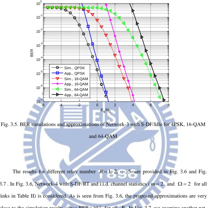
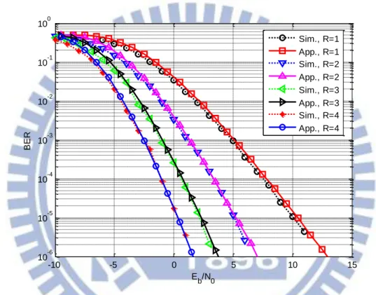
n for S-DF/RT ... 34 Fig. 3.4. BER simulations and approximations of Network-3 with S-DF/RT for 4PSK, 16-QAM and 64-QAM ... 35 Fig. 3.5. BER simulations and approximations of Network-3 with S-DF/Idle for 4PSK, 16-QAM and 64-QAM ... 36 Fig. 3.6. BER simulations and approximations of Network-4 with S-DF/RT for R1, 2, ,5 and i.i.d channel conditions (m2and 2 for all links) ... 37 Fig. 3.7. BER simulations and approximations of Network-5 with S-DF/Idle for R1, 2, ,5 over Rayleigh fading channels ... 37 Fig. 4.1. Destination BER simulation results and approximations for Network-1 ... 52 Fig. 4.2. Relay BER/PER simulation results and approximations for Network-1 ... 52
Fig. 4.3. BER simulations and approximations of Network-2 with the values of n1, 2 and 4
for S-DF/Idle ... 53 Fig. 4.4. BER simulations and approximations of Network-2 with the values of n1, 2 and 4
for S-DF/RT ... 53 Fig. 4.5. BER simulations and approximations of Network-4 with S-DF/RT for
1, 2, 3 and 4
R and i.i.d channel conditions (m2 and 2for all links) ... 54 Fig. 4.6. BER simulations and approximations of Network-5 with S-DF/Idle for
1, 2, 3 and 4
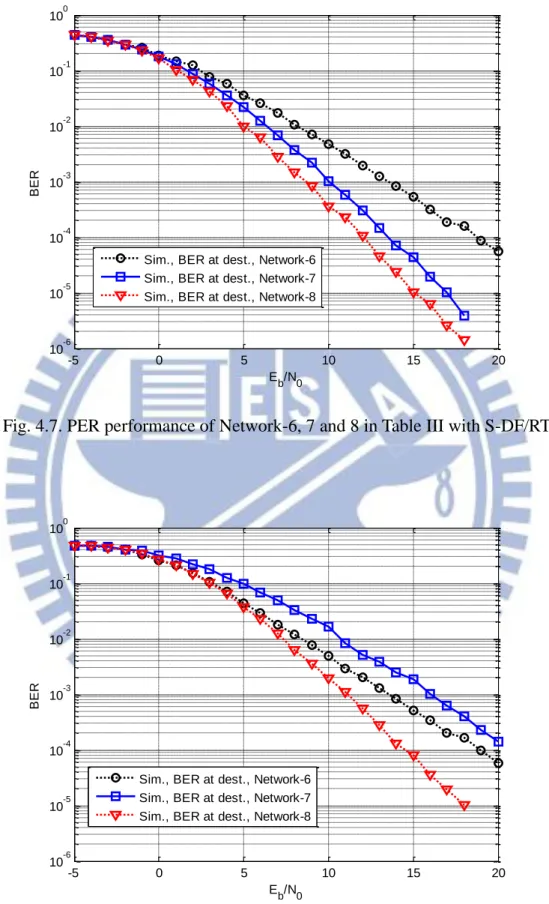
R over Rayleigh fading channels ... 55 Fig. 4.7. PER performance of Network-6, 7 and 8 in Table III with S-DF/RT ... 56 Fig. 4.8. PER performance of Network-6, 7 and 8 in Table III with S-DF/Idle ... 56 Fig. 5.1. The curves of MAF
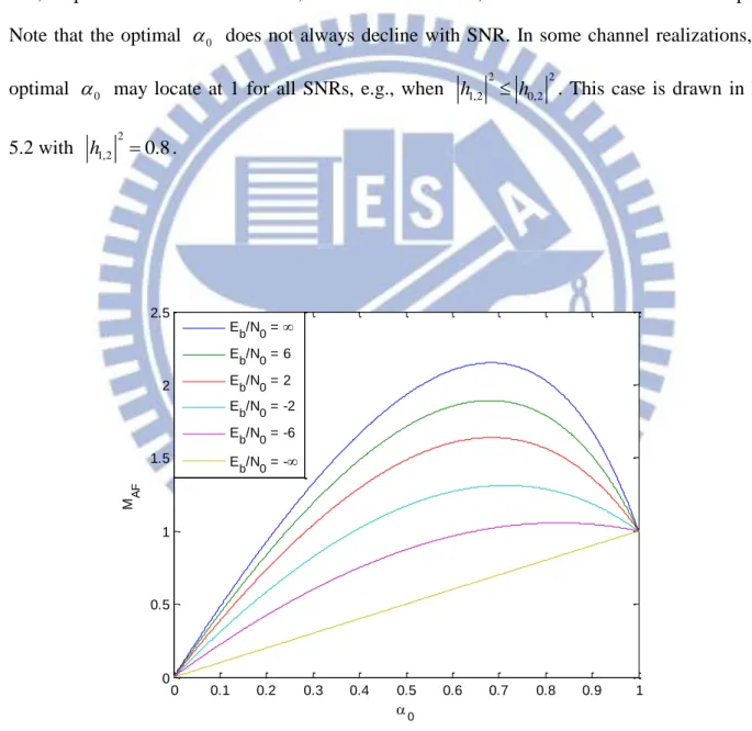
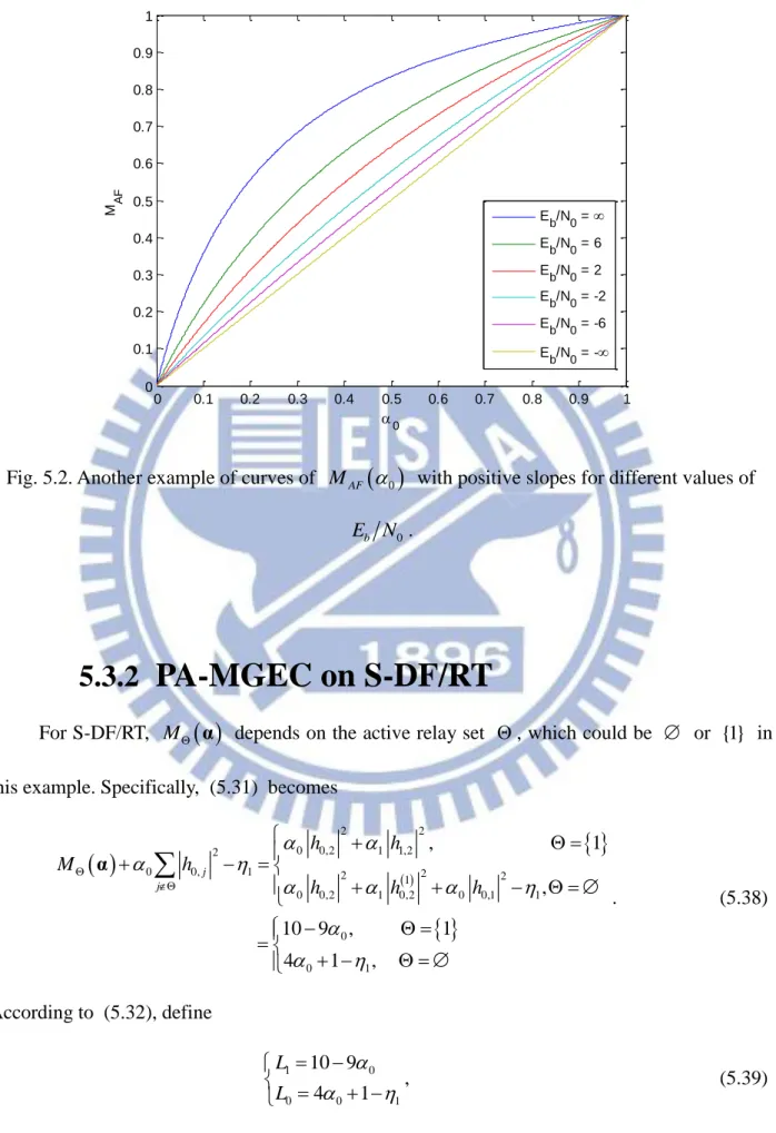
0 for Network-9 with different values of E N . ... 71b 0Fig. 5.2. Another example of curves of MAF
0 with positive slopes for different values of0
b
E N . ... 72
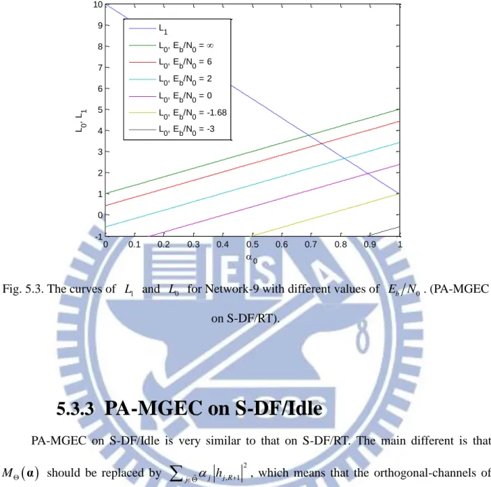
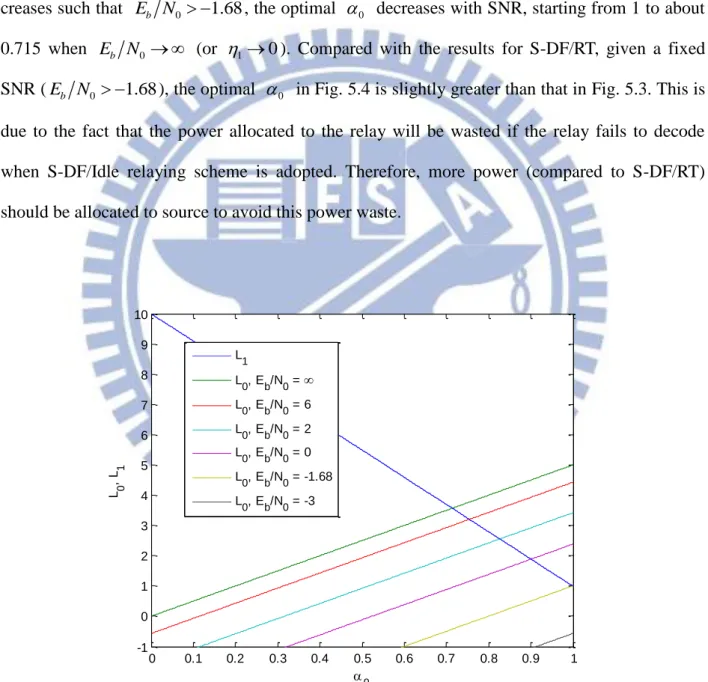
Fig. 5.3. The curves of L and 1 L for Network-9 with different values of 0 E N . b 0
(PA-MGEC on S-DF/RT). ... 74 Fig. 5.4. The curves of L and 1 L for Network-9 with different values of 0 E N . b 0
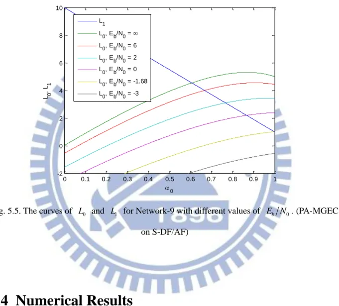
(PA-MGEC on S-DF/Idle) ... 75 Fig. 5.5. The curves of L and 0 L for Network-9 with different values of 1 E N . b 0
(PA-MGEC on S-DF/AF)... 77 Fig. 5.6. Power allocation results for PA-EG and PA-EC on Network-9 with AF relaying scheme. ... 78 Fig. 5.7. BER simulation results for PA-EG and PA-EC on Network-9 with AF relaying scheme. ... 79 Fig. 5.8. Power allocation results for PA-EG, PA-ABER and PA-MGEC on Network-9 with S-DF/RT relaying scheme. ... 80
Fig. 5.9. BER simulation results for PA-EG, PA-ABER and PA-MGEC on Network-9 with
S-DF/RT relaying scheme. ... 80
Fig. 5.10. Power allocation results for PA-EG, PA-ABER and PA-MGEC on Network-9 with S-DF/Idle relaying scheme. ... 81
Fig. 5.11. BER simulation results for PA-EG, PA-ABER and PA-MGEC on Network-9 with S-DF/Idle relaying scheme. ... 82
Fig. 5.12. Power allocation results for PA-EG, PA-ABER and PA-MGEC on Network-9 with S-DF/AF relaying scheme. ... 83
Fig. 5.13. BER simulation results for PA-EG, PA-ABER and PA-MGEC on Network-9 with S-DF/AF relaying scheme. ... 83
Fig. 5.14. Power allocation results for PA-EG and PA-EC on Network-10 with AF relaying scheme. ... 85
Fig. 5.15. BER simulation results for PA-EG and PA-EC on Network-10 with AF relaying scheme. ... 85
Fig. 5.16. Power allocation results on Network-10 with S-DF/RT relaying scheme. ... 86
Fig. 5.17. BER simulation results on Network-10 with S-DF/RT relaying scheme. ... 86
Fig. 5.18. Power allocation results on Network-10 with S-DF/Idle relaying scheme. ... 87
Fig. 5.19. BER simulation results on Network-10 with S-DF/Idle relaying scheme. ... 87
Fig. 5.20. Power allocation results on Network-10 with S-DF/AF relaying scheme... 88
Fig. 5.21. BER simulation results on Network-10 with S-DF/AF relaying scheme. ... 88
Fig. 5.22. Power allocation results on Network-11 with AF relaying scheme. ... 89
Fig. 5.23. BER simulation results on Network-11 with AF relaying scheme. ... 90
Fig. 5.24. Power allocation results on Network-11 with S-DF/RT relaying scheme. ... 90
Fig. 5.25. BER simulation results on Network-11 with S-DF/RT relaying scheme. ... 91
Fig. 5.26. Power allocation results on Network-12 with AF relaying scheme. ... 92
Fig. 5.28. Power allocation results on Network-12 with S-DF/RT relaying scheme. ... 93
Fig. 5.29. BER simulation results on Network-12 with S-DF/RT relaying scheme. ... 93
Fig. 5.30. Power allocation results on Network-12 with S-DF/Idle relaying scheme. ... 94
Fig. 5.31. BER simulation results on Network-12 with S-DF/Idle relaying scheme. ... 94
Fig. 5.32. Power allocation results on Network-12 with S-DF/AF relaying scheme... 95
Fig. 5.33. BER simulation results on Network-12 with S-DF/AF relaying scheme. ... 95
Fig. 5.34. Power allocation results on Network-13 with S-DF/Idle relaying scheme. ... 96
Fig. 5.35. BER simulation results on Network-13 with S-DF/Idle relaying scheme. ... 97
Fig. 6.1. Four example mappers
G, A, B, C
for the 16-QAM constellation. The signal point labels
v v v vG; A; B; C
are in hexadecimal format, where v , G v , A v and B v are to C denote the label of G, A, B and C, respectively. (The A, B and C mappers are the MBER mappings which maximize the minimum Euclidean distance between transmit symbols for the second, third and fourth transmissions of the hybrid automatic repeat-request system in [82], respectively.) ... 104Fig. 6.2. The curves of L , 0 L and 1 L for Network-9 with different values of 2 E N . b 0 (PA-MGEC on S-DRF/RT) ... 110
Fig. 6.3. The curves of L , 0 L and 1 L for Network-9 with different values of 2 E N . b 0 (PA-MGEC on S-DRF/Idle) ... 112
Fig. 6.4. The curves of L , 0 L and 1 L for Network-9 with different values of 2 E N . b 0 (PA-MGEC on S-DRF/AF) ... 114
Fig. 6.5. Power allocation results for PA-EG, PA-ABER and PA-MGEC on Network-9 with S-DRF/RT relaying scheme. ... 115
Fig. 6.6. BER simulation results for PA-EG, PA-ABER and PA-MGEC on Network-9 with S-DRF/RT relaying scheme. ... 116 Fig. 6.7. Power allocation results for PA-EG, PA-ABER and PA-MGEC on Network-9 with
S-DRF/Idle relaying scheme. ... 117
Fig. 6.8. BER simulation results for PA-EG, PA-ABER and PA-MGEC on Network-9 with S-DRF/Idle relaying scheme. ... 117
Fig. 6.9. Power allocation results for PA-EG, PA-ABER and PA-MGEC on Network-9 with S-DRF/AF relaying scheme. ... 118
Fig. 6.10. BER simulation results for PA-EG, PA-ABER and PA-MGEC on Network-9 with S-DRF/AF relaying scheme. ... 119
Fig. 6.11. Power allocation results on Network-14 with S-DRF/RT relaying scheme. ... 121
Fig. 6.12. BER simulation results on Network-14 with S-DRF/RT relaying scheme. ... 121
Fig. 6.13. Power allocation results on Network-14 with S-DRF/Idle relaying scheme. ... 122
Fig. 6.14. BER simulation results on Network-14 with S-DRF/Idle relaying scheme. ... 122
Fig. 6.15. Power allocation results on Network-14 with S-DRF/AF relaying scheme. ... 123
Fig. 6.16. BER simulation results on Network-14 with S-DRF/AF relaying scheme. ... 123
Fig. 6.17. Power allocation results on Network-15 with S-DRF/AF relaying scheme. ... 124
List of Tables
Table I. Values of N , l C and i D for 3 square constellations with Gray mappings ... 22i
Table II. Network Setups ... 33
Table III. Network setups ... 54
Table IV. Network setups used in Chapter 5 ... 70
Table V. for Setup-1, Setup-2 and Setup-3 ... 103
Table VI. ˆ for Setup-1, Setup-2 and Setup-3 ... 105
Notations
j : -1 ( ) T: transpose of a matrix or vector
Ex
: expectation operator with respect to variable x Re{} : real parts 1: all 1 vector
exp
: exponential function
: Gamma functionChapter 1
Introduction
Today, a wide variety of wireless communication systems have been deployed around the world to provide users with un-tethered telecommunication services. The users’ ever increasing demands on better quality of service (QoS), higher transmission rate and lower cost, however, still keep driving the development of more advanced wireless communication technologies and systems. The design of future generations of wireless communication systems is aimed to provide users with low-power consumption, low-cost, high-quality multi-media services anytime, anywhere and at any mobility. Unfortunately, transmissions through wireless channels suffer from various radio impairments, including propagation loss, multi-path fading, shadowed fading and co-channel interference [1]-[4]. Such impairments will become even severer under high-rate and/or low-power constraints and have to be overcome before the design objective can become a reality.
To cope with multipath fading, diversity techniques are commonly considered. The idea is to transmit copies of the signals through multiple (independent) channels, which may be created in time, frequency, or space. Multiple-input multiple-output (MIMO) has been known as one of the most effective techniques [3]-[10]; by using multiple antennas at both transmitter and receiver, MIMO is able to provide not only diversity gain against multi-path fading, but also array gain
(power gain), and/or degree-of-freedom gain over the single-input and single-output (SISO) tech-nique. However, since multiple antennas are usually installed on the same device, MIMO is not good at counteracting propagation loss or shadowed fading.
On the other hand, cooperative relaying [11]-[14] has emerged as a promising technique; by allowing other nodes to cooperate with the source to transmit data to the destination, the propagation loss and shadowed fading can be reduced, and the co-channel interference can be removed largely. In addition, the “virtual antenna array” formed by the source and the coopera-tive nodes can also be exploited to provide cooperacoopera-tive diversity to mitigate the effects of mul-ti-path fading. Cooperative diversity has been regarded as the most practical space diversity tech-nique for size-limited devices in which mounting multiple antennas is not feasible [15]-[18], and has been adopted in today commercial standards, such as 3GPP-LTE (long term evolution) [19] and IEEE 802.16j [20].
1.1 Cooperative Relaying
In the cooperative relaying, thanks to the broadcast nature of wireless communications, some other nodes (called relays) are allowed to overhear the packet transmitted from the source and help relay it to the destination to improve communication performance. Two relaying modes have been explored extensively in the literature: one is amplify-and-forward (AF, or non-regenerative) and the other decode-and-forward (DF, or regenerative). In the AF relaying, a relay simply for-wards the signals received from the source to the destination without any decoding. To keep a constant transmit power at the relays, the signals are forwarded either with variable-gain normal-ization [16], [21]-[25] or fixed-gain normalnormal-ization [26]-[28]. The AF relaying has been shown to achieve full diversity in Rayleigh fading channels [16] and in Nakagami-m fading channels [28]. In the DF relaying, a relay decodes the packet received from the source, re-encodes and forwards it to the destination. The relay can always forward the packet to the destination, or it
does the forwarding only if the packet is decoded correctly. The former is called the fixed DF (F-DF) and the latter the selection DF (S-DF) relaying. In [16], it was shown that the F-DF does not achieve a full diversity in Rayleigh fading channels, but S-DF does. In practice, S-DF can be implemented easily with a cyclic redundancy check (CRC) [30]. In addition, two modes of opera-tion can be differentiated within the S-DF relaying: one is S-DF with source idle (S-DF/Idle) [31]-[40], and the other S-DF with source retransmission (S-DF/RT) [16]. In S-DF/Idle, the source keeps silent in the case of relay decoding failure whereas in the S-DF/RT, the source re-transmits the packet on the relay’s behave. Recently, a hybrid relaying method involving S-DF and AF (denoted by S-DF/AF) has been proposed in which a relay uses AF upon decoding failure [41]-[44] otherwise S-DF is used. Generally speaking, S-DF/AF and S-DF/RT outperform S-DF/Idle but with higher complexities on decoding and signaling.
Although DF relaying is more complex than AF due to the need of decoding and re-encoding before forwarding, it allows the relay to use a different channel code or modulation from source to acquire additional gains. The former is usually called coded cooperation [45][46] and the later the decode-remap-and-forward (DRF) relaying [47]-[50]. In DRF, the basic idea is to enlarge the minimum overall Euclidean distance seen at the destination by changing the map-pers at relays so as to obtain a remapping gain. The concept of constellation-remapping was originally devised in the multiple-packet transmissions such as H-ARQ (hybrid automatic repeat request) and has been shown to offer significant gain over those without remapping for both coded and uncoded systems [51][52].
1.2 BICM
Coded modulation has been known as a high spectrum-efficient technique for high-data-rate transmission [53]-[58]. Trellis coded modulation (TCM) was first devised for AWGN (additive white Gaussian noise) channels in [53], where the Euclidean distance between coded sequences
is maximized. Its performance, however, significantly is degraded in fading channels because of its very low diversity order. In [57], a bit-wise interleaver is employed between the channel en-coder and modulator to allow a coded modulation system to achieve a higher diversity order with a moderate complexity. The scheme is later known as the bit-interleaved coded modulation (BICM), and its diversity order was proved to be the free distance of the outer code, under the fast Rayleigh fading environment [58].
The main idea of BICM is to transmit the coded bits over independent channels for gaining the diversity. With the use of interleaving and de-interleaving, the independent channels can be obtained through time for high mobility users, through frequency for OFDM (orthogonal fquency-division multiplexing) systems, and/or through space for multi-antenna systems. As a re-sult, BICM has been used widely in nowadays systems [59][60].
Very recently, studies have begun to look at the BICM-coded cooperative relaying net-works [61]-[65]. For example, bit error rate (BER) performance of a BICM-coded cooperative network was analyzed in [61] with the F-DF relay being modeled by a post-BSC (binary sym-metric channel). Reference [62] evaluated the achievable rates for different combinations of modulation and number of antennas used at the source and relay nodes. Pre-coding for a non-orthogonal AF was studied in [63] aiming to achieve maximum diversity order and high coding gains. For the BICM-coded cooperative OFDM systems, [64] considered the relay selec-tion and sub-carrier allocaselec-tion with AF relaying in order to minimize the asymptotic worst-case, pair-wise error probability, whereas [65] considered the issue of relay placement with DF relay-ing.
The objective of this dissertation is to investigate the BICM-coded cooperative relaying network in the aspects of performance analysis and power allocation.
1.3 Performance Analysis
The performance analysis of the cooperative relaying networks has been a topic of exten-sive research, e.g., [16]-[28] for AF and [31]-[40] for S-DF. The analyses were done over the Rayleigh fading channels from the aspects of capacity [21][31], outage probability [16][22][23][27][32][33] and un-coded symbol-error-rate (SER) [27][34][35], respectively. Very recently, the analysis has been extended to the Nakagami-m fading channels in [36]-[40] for the un-coded network. The Nakagami-m channel has been considered as a generalized channel model due to its great versatility, in the sense that it has better flexibility and accuracy in matching vari-ous real wireless environments than Rayleigh, log-normal or Rician distributions [29]. In particu-lar, in [36], SER was analyzed for a single-relay network under the correlated and uncorrelated channels, and exact SER was provided in [37] for the multiple-relay networks. In [38], an as-ymptotic SER approximation is provided, and with that a power allocation was proposed. In [39], a close-form expression for the moment generating function of the received signal-to-noise ratio (SNR) at the destination was derived, and it was used to evaluate the average SER, outage proba-bility and the average channel capacity. Lastly, in [40], SER and diversity order were investigated for the networks with inter-relay links.
For the BICM-coded cooperative relaying network, BER analyses with AF relays are pro-vided in [66][67]. However, to the best of our knowledge, the existing works on S-DF propro-vided the analysis only for the un-coded systems (cf. [34]-[40]). In addition, the S-DF was based on a symbol-by-symbol forwarding strategy, where symbols are detected separately, and only the cor-rect symbols are forwarded to the destination. In real systems, nevertheless, a CRC can only de-tect whether a packet is in error rather than the exact erroneous locations. Furthermore, such a symbol-based forwarding requires additional signaling overheads to indicate the locations of the correct symbols, and that increases the complexity very significantly. Therefore, this dissertation considers BICM-coded cooperative relaying system with a packet-by-packet forwarding strategy
which is more practical in real systems.
1.4 Power Allocations
Transmit power allocation between source and relay nodes is a critical design issue in the cooperative networks where sources and relays are powered by batteries. An effective power al-location between transmit nodes could significantly lower the error rate at the destination so as to reduce the probability of re-transmission via (H-)ARQ [68] (which requires additional pow-er/energy and radio resources). Moreover, a good transmit power allocation method should in-volve relay selection as well, e.g., allocate zero power to the useless relays. Recently, it has been widely discussed in the literature. For examples, the capacity is maximized for a 3-node F-DF relaying network in [69] based on full channel state information (CSI). The outage probability was minimized in [70] through joint power allocation and relay positioning for multiple DF or AF relays. Reference [71] proposed a relay selection and power allocation scheme to prolong the lifetime of the DF cooperative network under a non-outage constraint, whereas [72] aimed to maximize the sum-rate. Uncoded SER was analyzed and minimized via power allocation in [34] for a 3-node DF cooperative network, while [73] dealt with BER. Joint subcarrier and power al-location for an uncoded OFDM system with AF relays is investigated in [74].
In most of the existing works, power allocation was designed either from an infor-mation-theoretic viewpoint [69]-[72] or to minimize un-coded SER or BER [34][73][74]. As to the power allocation on BICM-coded cooperative systems, [64] considered the power allocation of a BICM-OFDM system with the AF relaying. Our previous work [75] considered a 3-node network with an S-DF/Idle relay, and which is then extended in [50] to a multiple-relay network with DRF relays. However, the power allocation is still an open question for S-DF/RT and S-DF/AF.
1.5 Dissertation Outline and Contributions
This dissertation focuses on performance analysis and power allocation for a BICM-coded cooperative relaying network. Since the performance analysis of AF has been discussed in [66][67], the performance analyses in this dissertation mainly focus on S-DF. For the perfor-mance analysis part, unlike the existing works which considered uncoded S-DF with sym-bol-by-symbol forwarding strategy, this dissertation is the first work that studies the BICM-coded cooperative relaying network with packet-by-packet forwarding strategy. The target is to provide the analysis of BER performance at the destination and the diversity order of the network for both S-DF/RT and S-DF/Idle over both fast-fading and block-fading Nakagami-m channels. For the power allocation part, a comprehensively investigation is proposed for not only the AF, S-DF/RT, S-DF/Idle and S-DF/AF relaying (based on a packet-by-packet forwarding) but also DRF relays. Based on the knowledge of perfect CSI, the target is to allocate power to minimize the BER at the destination, while taking into account the probability of decoding failure at relays. To avoid the cumbersome (if not impossible) evaluation of the exact BER and an inefficient exhaustive search of the optimal power, simplified cost functions which can be optimized efficiently through exist-ing algorithms are proposed for individual modes. The objective is to determine the transmit power allocation that minimizes the BER at the destination. Outline and contributions of this dis-sertation are as follows.
Chapter 2 first describes the network model and the channel statistics. The BICM modulation at the source and the corresponding decoding at relays at the phase-I are given. Then, the model of signals forwarded at phase-II are introduced for AF, S-DF/RT, S-DF/Idle and S-DF/AF, fol-lowing by a general formulation that is used to describe the decoding at the destination and will be further employed in the derivations of all the following chapters.
Chapter 3 investigates the BER performance and diversity order for S-DF/RT and S-DF/Idle over fast-fading Nakagami-m channels with a packet-by-packet forwarding strategy. Given a set
of active relays, this Chapter first derives the approximation of BER at the destination by extend-ing the expurgated bound proposed in [58]. But, unlike [58] which employed the Chernoff bound to obtain the expurgated bound, a close-form evaluation is proposed. Such an evaluation can be degenerated to calculate the error rate at relays so that the overall BER at the destination is ob-tained. To find out the diversity of the network, the asymptotic upper and lower bounds are de-rived by considering only the worst case error events between coded sequences and signal point pairs with the shortest Euclidean distance in the constellation. By showing that both bounds achieve the same diversity order, the diversity order of the network is obtained. Numerical results show that our approximations are rather accurate (within a 0.4dB gap to the true BER) for differ-ent network setups.
Chapter 4 studies the BER performance and diversity order for block-fading Nakagami-m channels. For the BER analysis, the BER for a given active relay set can be obtained by first ob-taining the BER in AWGN channels before averaging it over channel realizations. Unfortunately, a direct integration may lead to a non-trivial gap to the exact performance due to the severe loss at low SNR regions in AWGN case. As a result, the BER in AWGN is modified and the Monte Carlo method is used for the channel averaging. The diversity of the cooperative BICM network is also derived for both S-DF/RT and S-DF/Idle. Numerical results are given to show that our ap-proximations are rather accurate for different network setups. An example is also provided to ver-ify our proof of the diversity order.
Chapter 5 investigates the power allocation of the cooperative BICM relaying network. Four relaying schemes are considered: AF, S-DF/RT, S-DF/Idle and S-DF/AF with the general formu-lation given in Chapter 2. For AF, by simplifying the union bound, an approximate BER is de-rived and shown to be monotonically decreasing with an equivalent channel gain so that the power allocation method named PA-EC is proposed which takes the equivalent channel as the cost function. For the S-DF relaying modes, two power allocation methods are proposed: PA-ABER based on approximate BER and PA-MGEC based on minimum generalized equivalent
channel. In PA-ABER, the approximate BER is shown to be a convex function for S-DF/RT, S-DF/Idle and S-DF/AF. Therefore, gradient method can be adopted to find the solution. Then PA-MGEC transforms PA-ABER to a max-min problem, which can be optimized with even low-er complexity. Examples are given to demonstrate how powlow-er is allocated for PA-EC and PA-MGEC on the AF and S-DF relaying modes. Simulation results confirm that our proposed methods have the ability to properly allocate power according to the SNR value and the channel realizations. The proposed methods outperform the equal gain power allocation (PA-EG) with large margins for different network setups.
Chapter 6 considers S-DRF relays which are allowed to change the mappers before forward-ing so as to obtain an addition remappforward-ing gain. The proposed methods, PA-ABER and PA-MGEC, in Chapter 5 are extended in this chapter for the remapping case. Examples are provided to demonstrate how power is allocated, and numerical results confirm that the proposed method outperform PA-EG with large margins for different network setups.
Finally, Chapter 7 concludes the dissertation and discusses some possible extensions and fu-ture research topics.
Chapter 2
System Model
2.1 Network Model
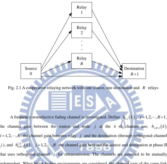
This dissertation considers a cooperative relaying network as shown in Fig. 2.1 with one source, R relays and one destination, which are indexed by 0, 1,,R, and R1, respectively. Each node is equipped with one antenna. Relays operate in the half-duplexing manner implying that they cannot transmit and receive simultaneously. Transmission of a packet is divided into two phases; at phase-I, the source broadcasts a packet to relays and the destination. In cases of the relaying mode used, at phase-II, either relays or the source forward(s) the received packet over orthogonal channels to the destination. In the following, the orthogonal channel allotted to relay
Source 0 Destination Relay Relay 1 Relay 2 . . . R 1 R
Fig. 2.1 A cooperative relaying network with one source, one destination and R relays
A frequency-nonselective fading channel is investigated. Define h0, j
k , j1, 2, ,R 1, the channel gain between the source and node j at the k -th channel use, hj R, 1
k1, 2, ,
i R the channel gain between relay j and the destination (through orthogonal-channel
j ), and h0, jR1
k , j1, 2,,R the channel gain between the source and destination at phase-II that uses orthogonal-channel j for retransmission. The channels are assumed to be mutually independent. When block-fading environments are considered, the channel gain of the same link is assumed constant during the transmission of a packet and changes from packet to packet. For fast-fading environments, under the assumption of a symbol interleaver with a depth larger than the channel coherent time, the channel gains of the same link are independent and identically distributed (i.i.d.) over different time index k.The general Nakagami-m fading model is adopted, with the probability density function (PDF) [29]
2
2 1 2 exp m m m m h mh p h m (2.1)for the channel gain h, where m is the shaping factor (assumed to be an integer), is the average power, and
is the Gamma function [76]. Perfect receiver CSI (CSI-R) is assumed available at all receiving nodes.2.2
Bit-interleaved Coded Modulation (BICM)
BICM is employed at all nodes. At the source, an information bit sequence b of length K
is encoded into a coded sequence c of length N, as shown in Fig. 2.2(a). After interleaving, the resulting sequence v is partitioned successively into groups of l bits, called the labels. The
k -th label in v , denoted by v k , is then mapped to a complex symbols
x k for
transmission, according to a signal mapper and a signal constellation . At phase-I, the received signals at relays and the destination at time k are given by
0,j 0,j 0 0,j , 1, 2, , 1
y k h k P x k k j R , (2.2)
where P is the source transmit power, and 0 0, j
k is the AWGN (additive white Gaussian noise) at node j . All noises are modeled as i.i.d. zero-mean, circularly-symmetric complex Gaussian random variables with the variance N0 2 per dimension.Encoder Interleaver Grouping ( bits) Mapper
b
c
v
l
v k x k
,
Demapper De-inter.1 Decoder
ˆb
LLRs CRC
0, jy
k
Demapper De-inter.1 Decoder
LLRs
, 1 0,1, , j R y j R ˆb
(a) (b) (c)Fig. 2.2 Block diagrams of (a) the transmitter at source, (b) receivers at relay j and (c) receiver at destination
When AF relaying is considered, the received packet will be forwarded without decoding. For the S-DF relayings (S-DF/RT, S-DF/Idle, S-DF/AF), the packet is first decoded before for-warding. Specifically, upon receiving y0, j
k , relay j calculates the simplified log-likelihoodratio (LLR) for the i -th bit of the k -th symbol, according to
0 1 2 2 0, 0, 0 0, 0, 0 0 0 min min i i j j j j x x y k h k P x y k h k P x N N , (2.3)where bi is the subset of signal points in with the binary value b at the i -th position of
the label. The LLRs of coded sequence are then de-interleaved and decoded, as shown in Fig. 2.2(b). The Max-log MAP (maximum a posteriori probability) decoder [77] is employed at all receiving nodes.
2.3 Signals in Phase-II for different Relaying Schemes
2.3.1
Amplify-and-Forward (AF)
In the AF relaying, each relay forwards the received packet through the orthogonal-channel with a power normalization so as to keep a constant transmit power. In this case, the received signals at destination at phase-II are
, 1 , 1 2 0, , 1 0 0, 0 , 1, 2, , j j R j R j j R j P y k h k y k k j R P h k N , (2.4)where P is the transmit power over orthogonal-channel j , and j j R, 1
k is the correspond-ing AWGN at destination. In (2.4), the variable-gain normalization is adopted. The received sig-nals at phase-I and phase-II are combined and decoded jointly at the destination, which will be described in Section 2.4.2.3.2
S-DF with Source Re-transmission
(S-DF/RT)
In S-DF/RT, relay j forwards the received packet to the destination if b is decoded correctly. Otherwise, it notifies the source to re-transmit the packet though OC- j . Define
1, , R
as the set of relays which have decoded successfully at phase-I. Then, at phase-II,
the signals received at destination are expressed by
, 1 , 1 , 1 , j R j R j j R y k h k P x k k j, (2.5) and
0, 1 0, 1 0, 1 , j j j R R j R y k h k P x k k j, (2.6)where 0, jR1
k is the corresponding AWGN at OC- j . Note that, in S-DF/RT, an ACK or NCK from relay j is required for the source before the beginning of Phase-II so as to know whether it should re-transmit the packet through OC- j or not.2.3.3
S-DF with Source Idle (S-DF/Idle)
In S-DF/Idle, the source keeps silent at phase-II. Nothing is going to be sent in OC- j at phase-II, if relay j fails to decode. Thus, only the signals in (2.5) are received at the destination. Note that, for S-DF/Idle, the relays do not have to send ACK or NCK back to source, and neither to the destination. The destination is supposed to know whether signals are transmitted on OC- j through power detection.
2.3.4
Hybrid S-DF/AF (S-DF/AF)
In S-DF/AF, relay j forwards the received packet to the destination if b is decoded correctly. Otherwise, it amplifies the packet and forwards it though OC- j . Thus, at phase-II, the signals received at destination are expressed by
, 1 , 1 , 1 , j R j R j j R y k h k P x k k j, (2.7) and
, 1 , 1 2 0, , 1 0 0, 0 , j j R j R j j R j P y k h k y k k j P h k N . (2.8)Note that additional signaling is required for the decoding at the destination (in Section 2.4) to know whether the forwarding on OC- j is by DF or AF.
2.4 General Form and Decoding at Destination
For simplicity and convenience, we re-arrange the received signals of the above 4 relayings at phase-II into a general form, which is
, 1 , 1 , 1 , 1, 2, , j R j R j j R y k h k P x k k j R. (2.9) In AF,
, 1 , 1 0 ,R+1 , 1 0, 2 0 0, 0 , 1 , 1 2 0, , 1 0 0, 0 , , j R j R j j R j j j j R j R j j R j y k y k P h k h k h k P h k N P k h k k k P h k N (2.10) with
2 , 1 , 1 2 0 0 0, 0 var j R j R j 1 j h k P k N P h k N . (2.11)Define
0 as the set of all active nodes, including the source. In S-DF/RT, terms in (2.9) are replaced by
, 1 , 1 0, 1 , 1 ,R+1 0, 1 , 1 ,R+1 0, 1 , if , , if , if , , if , if . , if j R j R j R j R j j R j R j j R y k j y k y k j h k j h k h k j k j k k j (2.12) In S-DF/Idle,
, 1 , 1 ,R+1 , 1 ,R+1 , 1 , for , , for , , for . j R j R j j R j j R y k y k j h k h k j k k j (2.13) And in S-DF/AF,
, 1 , 1 , 1 ,R+1 0 , 1 0, 2 0 0, 0 , 1 ,R+1 , , if , , if , j R j R j R j j R j j j R j y k y k h k j h k P h k h k j P h k N k k
, 1 2 0, , 1 0 0, 0 if . , if j j R j j R j j P h k k k j P h k N . (2.14)With the general form in (2.9)-(2.14), the LLR for the i -th bit of the k -th symbol at the destination is evaluated by
0 1 2 2 , 1 , 1 , 1 , 1 0 0 0 0 min min i i R R j R j R j j R j R j j j x j x j y k h k P x y k h k P x N N
, (2.15) where
2 , 1 0 2 0 0 0, 0 01 , for OC- with AF , otherwise j R j j j h k P N j N P h k N N . (2.16)
Note that for S-DF/Idle, the summation in (2.15) only takes the terms with j. The LLRs of the coded sequence are then de-interleaved and passed to the decoder, as shown in Fig. 2.2(c).
Chapter 3
Performance and Diversity
Anal-ysis in Fast-fading Channels
In this chapter, the BER performance at the destination and the diversity order of the BICM-coded cooperative network in fast-fading Nakagami-m channels for both S-DF/RT and S-DF/Idle schemes are discussed. For fast-fading environments, we assume a symbol interleaver with a depth larger than the channel coherent time such that the channel gains of the same link are independent and identically distributed (i.i.d.) over different time index k . In what follows, the BER analyses are presented first, followed by the diversity analyses.
3.1 BER Analysis
This section provides the analyses of BER at destination for the BICM-coded cooperative network with packet-by-packet forwarding strategy. The analysis of S-DF/RT is provided first, and that of S-DF/Idle is given by indicating the differences.
3.1.1
S-DF/RT
Let pb RRT, 1 denote the BER at the destination with the S-DF/RT relaying. Since pb RRT, 1
depends on , the decoding results at relays, it can be represented as
, 1 , 1 1,2, , , 1 , , 1,2, , Pr 1 RT RT b R b R R RT b R f j f j R j j p p p p p
, (3.1)where pb RRT, 1
is the BER at destination given the active set , and pf j, is the pack-et-error-rate (PER) at relay j . Both pb RRT, 1
and pf j, have experienced sufficient amount of channel realizations. It is worthy to remind that the BER in (3.1) is evaluated under the pack-et-by-packet based forwarding, rather than the impractical symbol-by-symbol based forwarding considered in [34]-[40]. In the following development, a close-form approximation of pb RRT, 1
is derived first, followed by that of pf j, .
Using the assumptions of ideal interleaving and symmetrization in [58], BICM can be re-garded as a linear code such that the codeword pair-wise error probability (PEP) depends only on the Hamming distance between two coded sequences. In this case, the pb RRT, 1
can be bound-ed by [78]
RT RT , 1 , h f N b R I h h d d p w d f d
, (3.2)where w dI
h is the total information bits of the error events with Hamming weight d divid-hed by K, d is the free distance of the code, and f
RT
,
h
f d is the PEP between two coded sequences with Hamming distance d , averaged over the channel realizations. h
In [58], fRT
dh,
was evaluated through a union bound fubRT
dh,
for a single-link Rayleigh fading channels. In this dissertation, where the parallel Nakagami-m fading channels areconsidered, the union bound is extended as
0 0 1 RT , 1 0 1 0 1 1 , 2 2 h j i i b b d l R s ub h s l x k z k i b k x k z k j ds f d s l s
j j j , (3.3) where j 1, and ,
j x k z k s is the moment generating function (MGF) of the metric
difference
, 1 , 1 , 1 , 1 , 1 , 1 2 2 2 , 1 0 ( ), ( ) log | , log | , exp j R j R j j R j R j R j R h k j j R h k j x k z k E p y k x k h k p y k z k h k P E s s h x z N k k . (3.4) Note that, in (3.4), 0 j 0N N for S-DF/RT and S-DF/Idle.
Unfortunately, as was discussed in [58], fubRT
dh,
is very loose at low-to-moderate SNRs due to that too many irrelevant z's are included in (3.3). To obtain a tighter bound, the expurgation proposed in [58] is proposed to provide a more accurate approximation, i.e.,
0 0 1 RT ˆ , 1 0 1 0 1 1 , 2 2 h j i b d l R s ex h s l x k z k i b k x k j ds f d s l s
j j j , (3.5)where all irrelevant z k 's in
i b are dropped, except ˆz k which is the unique nearest
neighbor of x k in
ib
. In [58], the Chernoff bound was introduced in the evaluation of (3.5),
which still introduces extra looseness on the bounds. Here, (3.5) is evaluated exactly through direct saddle point integration [79].
Firstly, we introduce Lemma-1 whose proof is given in Appendix A.
Lemma-1: Let h be a Nakagami-m random variable with shaping factor m and average power
, then
2
2
2
exp 1 m h E s s ah s s a m , (3.6) providing that1 1 1 1 2 4 2 4 m m s a a . (3.7)
Applying Lemma-1, (3.4) is derived as
, 1 2 , 1 2 ˆ , , 1 0 ˆ 1 j R j m j R j x k z k j R P x k z k s s s m N (3.8)with ROC given by
, 1 0 , 1 0 2 2 , 1 , 1 1 1 1 1 Re 2 ( ) ˆ( ) 4 2 ( ) ˆ( ) 4 j R j R j R j j R j m N m N s P x k z k P x k z k , (3.9) where , 1 , 1 , 1 , 1 0, 1 0, 1 , if , if , and , if , if j R j R j R j R R R m j j m m j j . (3.10)Since the saddle point 0.5 always falls in the ROC [79], the integration in (3.5) can be done along the vertical line s0.5 jt for all real number t . By substituting s0.5 jt and (3.8) into (3.5), one has
, 1 2 1 , 1 RT 2 ex 2 1 0 0 , 1 0 ˆ 1 1 1 , 1 1 4 2 4 4 h j R i b d m R l j R j h l i b x j j R P x z dt f d t l m N t
, (3.11)where the time index k has been dropped because mj R, 1, j R, 1 and the mapper are same for all k . In addition, (3.11) contains only the real part because, after rationalization, the imaginary part in the integral is an odd function of t .
Eq. (3.11) cares about only the Euclidean distance between x and ˆz , but not the actual locations of them. For the Gray mappings, some of
x z pairs in (3.11) have the same squared ,ˆ Euclidean distance xzˆ2 and hence can be grouped together. By doing so, (3.11) is re-written as
, 1 , 1 RT 2 ex 2 1 0 , 1 0 1 1 , 1 1 4 4 4 h j R d m R M j R j i h i i j j R P D dt f d C t m N t
, (3.12)where Di x zˆ2 is a squared Euclidean distance, C is the number of i
x z pairs with ,ˆ2
ˆ i
xz D over 2l l, and M is the number of distinct D 's. The values of i M , C and i D i
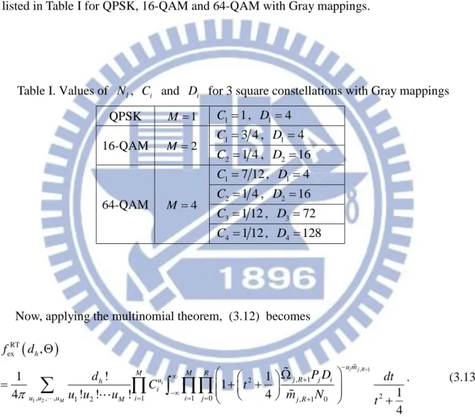
are listed in Table I for QPSK, 16-QAM and 64-QAM with Gray mappings.
Table I. Values of N , l C and i D for 3 square constellations with Gray mappings i
QPSK M 1 C11, D1 4 16-QAM M2 1 3 4 C , D1 4 2 1 4 C , D2 16 64-QAM M4 1 7 12 C , D14 2 1 4 C , D2 16 3 1 12 C , D3 72 4 1 12 C , D4 128
Now, applying the multinomial theorem, (3.12) becomes
, 1 1 2 RT ex , 1 2 2 , , , 1 2 1 1 0 , 1 0 , ! 1 1 1 1 4 ! ! ! 4 4 i j R i M h u m M M R j R j i u h i u u u M i i j j R f d P D d dt C t u u u m N t
. (3.13)The integration in (3.13) can be evaluated with partial fraction decomposition (PFD). Re-arrange the integration (to make the coefficient of t2 be 1) yields
, 1 , 1 , 1 , 1 2 2 1 0 , 1 0 2 1 0 , 1 , 1 2 , 1 0 , 1 0 , 1 , 1 0 1 1 1 4 4 1 1 1 1 4 4 i j R i j R i j R u m M R j R j i i j j R M R u m i j j R j i j R j i j R j R u m j R j i j R P D dt t m N t dt P D P D t t m N m N P D m N m
, 1 , , 2 1 0 , 1 0 2 , 1 1 2 2 , , 1 0 1 0 1 1 4 4 1 1 4 4 i j R i j i j M R u m i j j R j R j i B M R M R B i j i j i j i j dt N t t P D A A t t dt
, (3.14) where , , 1 0 , , 1 , 1 1 and 4 j R i j i j i j R j R j i m N A B u m P D . Using PFD yields
, , 1 , , 2 2 , 2 2 1 0 1 1 0 , 1 1 4 4 i j i j B M R B M R i j k i j k i j k i j i j E E A t t A t t
, (3.15) where
, , , , , , , , 1 ! i j i j i j i j B k B i j k B k i j i j s A d E A s G s B k ds (3.16)
1 4 1 4 s E s G s (3.17) and
, 1 , 1 0 1 4 i j M R B i j i j G s A s s
, (3.18)providing that A 's are different for distinct pairs i j,
i j . ,Using (3.15), the remaining integrals in (3.14) becomes