國立交通大學
資訊科學與工程研究所
碩士論文
以指令快取為基準之
低功耗分支目標暫存器
Low Power I-Cache-based BTB
研 究 生:黃富群
指導教授:單智君 博士
以指令快取為基準之低功耗分支目標暫存器
Low Power I-Cache-based BTB
研 究 生:黃富群 Student:Fu-Ching Hwang
指導教授:單智君 Advisor:Jyh-Jiun Shann
國 立 交 通 大 學
資 訊 科 學 與 工 程 研 究 所
碩 士 論 文
A ThesisSubmitted to Department of Computer and Information Science
College of Electrical Engineering and Computer Science
National Chiao Tung University
in partial Fulfillment of the Requirements
for the Degree of
Master
以指令快取為基準之低功耗分支目標
暫存器
學生: 黃富群 指導教授: 單智君 博士
國立交通大學資訊工程學系(研究所)碩士班
摘 要
減少耗電已經成為一種趨勢。分支目標暫存器是一個相當耗電的
裝置,提供管線化處理器動態的預測分支目標位址。這篇論文提出一
個以指令快取為基準的分支目標暫存器,能夠共享指令快取的 Tag 計
憶體。因此,以指令快取為基準的分支目標暫存器其靜態與動態耗能
均低於傳統的分支目標暫存器,並且,提出可分享使用分支目標暫存
器項目的設計來加強分支預測準確率。研究結果顯示,以指令快取為
基準的分支目標暫存器能夠節省 24%的靜態耗能,42%的動態耗能,
亦即 33%的整體系統耗能。
Low Power I-Cache-based BTB
Student: Fu-Ching Huang Advisor: Dr. Jyh-Jiun Shann
Department of Computer Science and Information Engineering
College of Electrical Engineering and Computer Science
National Chiao Tung University
ABSTRACT
Reducing power consumption has gained much attention recently. BTB is a
power-hungry device that supports dynamic branch prediction for pipelined processor.
This thesis proposes and instruction cache based BTB architecture called ICBTB. It
shares the tag memory with L1 instruction cache. Therefore, both static and dynamic
power consumption of ICBTB are lower than that of a typical BTB. Moreover, a BTB
誌 謝
首先感謝我的指導老師 單智君教授,在老師的諄諄教誨、辛勤
指導與勉勵下,我得以順利完成此論文,並且順利通過畢業口試。同
時感謝我的口試委員 鍾崇斌教授以及 謝萬雲教授,在他們的建議之
下,使此篇論文更加完整。
此外,感謝實驗室的學長 – 喬偉豪學長,以及實驗室全體學長
姐、同學、以及學弟們,每次都不厭其煩的與我討論許多問題,給我
意見和鼓勵,讓我的研究生活充滿歡樂與學習。
最後,感謝我的家人,謝謝你們在背後全心全意地支持我,讓我
在研究的路上走得更順利,無後顧之憂的學習,讓我追求自己的理想。
謹向所有支持我、勉勵我的師長與親友,獻上最誠摯的祝福,謝
謝你們。
黃富群
2006.08.28
Table of Contents
Chapter 1. INTRODUCTION ...1
1.1 Importance of Low Power Design ...1
1.2 Power Components of CMOS Circuit...1
1.3 Importance of Low Power Design on Dynamic Branch Prediction ...2
1.4 Introduction of I-Cache ...3
1.5 Introduction of Branch Target Buffer...5
1.6 Similar Features of I-Cache and BTB...7
1.7 Our Design ...8
1.8 Thesis Organization ...8
Chapter 2. BACKGROUND & RELATED WORK...9
2.1 Related Work on Low Power BTB ...9
2.2 Related Work on I-Cache Based BTB...9
2.3 Energy Consumption Analysis of BTB ... 11
Chapter 3. DESIGN ...13
3.1 Mapping method between Cache line and BTB entry...14
3.1.1 Group Mapping...15 3.1.2 Sharing Policy...20 3.1.3 Global BTB ...25 3.2 BTB management: ...28 3.2.1 Identification ...28 3.2.2 Placement...29 3.2.3 Replacement ...31 Chapter 4. EVALUATION ...32 4.1 Evaluation metrics ...32 4.2 Evaluation environment ...32
4.3 Evaluation methodology and result...33
Chapter 5. CONCLUSION & FUTURE WORK ...45
5.1 Conclusion ...45
List of Figures
Fig. 1 Power Trend...2
Fig. 2 Introduction of I-Cache ...4
Fig. 3 Structure of 4-way I-Cache...5
Fig. 4 Introduction of BTB ...6
Fig. 5 Structure of direct-map BTB ...7
Fig. 6 Johnson's BTB ...10
Fig. 7 Power components... 11
Fig. 8 System Overview...13
Fig. 9 Number of branch instruction per cache line...14
Fig. 10 Group Mapping...15
Fig. 11 Group Distance ...16
Fig. 12 Logic diagram of group mapping – set-based ...16
Fig. 13 Logic diagram of group mapping – way-based ...17
Fig. 14 Mapping circuit...18
Fig. 15 Sharing policy...20
Fig. 16 Logic diagram of sharing policy...21
Fig. 17 Lookup policy - line based ...22
Fig. 18 Lookup policy - instruction based ...23
Fig. 19 Sharing circuit...24
Fig. 20 Global BTB...25
Fig. 21 Logic diagram of Low Power I-Cache based BTB ...26
Fig. 22 Check circuit...27
Fig. 23 Logic diagram of Low Power I-Cache based BTB ...29
Fig. 24 All cases of placement ...30
Fig. 25 Placement circuit ...30
Fig. 29 Power Consumption of Different Configuration in A8 microprocessor...34
Fig. 30 Total energy consumption of group mapping ...35
Fig. 31 Total items of group mapping...35
Fig. 32 Power consumption of group mapping...36
Fig. 33 Total energy consumption of sharing policy...37
Fig. 34 Total items of sharing policy ...37
Fig. 35 Power consumption of sharing policy ...38
Fig. 36 Total energy consumption of global BTB...39
Fig. 37 Total items of global BTB ...39
Fig. 38 Power consumption of global BTB ...40
Fig. 41 Power consumption of sharing policy + global BTB ...42 Fig. 42 Total items of best case 4to2-s1-g2 ...42 Fig. 43 Power consumption of different lookup policy ...43 Fig. 44 Branch prediction accuracy and different sharing distance in direct map
I-Cache...44 Fig. 45 Branch prediction accuracy and different sharing distance in set associative
I-Cache...44 Fig. 46 Number of instructions per branch in Mibench...49
Chapter 1.
INTRODUCTION
1.1 Importance of Low Power Design
As the progress of technique, more and more products pay much attention to its
limit life time of battery-powered equipments and heat releasing problems. The
battery-powered equipments, as like MP3 player, PDA and etc. , would prefer more
and more life time to work. The heat would affect the stability of system and the bad
heat releasing policy may cause more power consumption on releasing heat and
decrease the life time of battery-powered equipments. Low power design would be
helpful to increase the life time of battery-powered equipments and reduce the heat
producing.
1.2 Power Components of CMOS Circuit
Today, CMOS technology is the dominant semiconductor technology for
microprocessors, memories and application specific integrated circuits (ASICs). In
CMOS circuit, its power components can be divided into twp kinds – dynamic power
and static power. Dynamic power is composed of switching power and short-circuit
power. Switching power is dissipated by charging and discharging the gate output
capacitance. Short-circuit power is, during logic gate operation, caused by VDD and
VSS may be inter mittently shorted. There are three major components to static
power.1> Sub-threshold leakage from Source to Drain. 2> Gate leakage. 3> Reverse
bias junction leakage. Sub-threshold leakage is the most dominant component to static
power consumption. It should also be noted that static power is generally a product of
In most cases, switching dominates the dynamic power. Thus, many related
researches which are for reducing dynamic power are focus on reducing switching
power. However, the static power begins to dominate the total power consumption as
process technology moves below 0.1 um as showed in fig[1].(Reference - 9) Therefore, how to reduce both dynamic and static power simultaneously becomes an
important research issue.
Fig. 1 Power Trend
predict branch direction and next instruction address of each branch instruction
dynamically. Moreover, dynamic branch prediction performs well branch prediction
accuracy from 90% to 98%.
Dynamic branch prediction is typically performed at the first pipeline stage to
eliminate pipeline stalls due to branches. A drawback arises here: since the fetched
instruction can not be identified as a branch or not at this stage, the dynamic branch
predictor is always exercised, Worse yet, the branch target buffer(BTB) which
supports dynamic branch prediction is a large storage with both tag and data
memories. Thus, dynamic branch prediction is a power-hungry technique in both
dynamic and static power while it is still very attractive to processors for power-miser
application due to its success in performance designs.
1.4 Introduction of I-Cache
In today processor design, instruction cache (I-Cache) is a indispensable
structure to provide instructions every cycle which dominates dynamic and static
power consumption of total system.
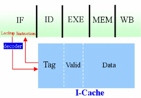
I-Cache is composed of valid bit, tag array and data array as showed in fig[2]. The organization of I-Cache is divided into three kinds: direct-map, set-associative
and fully-associative. I-Cache is low-way set associative organization in common and
the address space is program counter. The cache line size mostly is 8 to 16
Fig. 2 Introduction of I-Cache
It is usually included read and write operation in I-Cache(fig[3]). Take the five stages pipelines in MIPS for example. Instruction fetcher would read I-Cache in If
stage by index part of program counter to index the corresponding cache line. Then,
compare the tag part of program counter to tag field of I-Cache and rely on the valid
bit to identify hit or not. The write operation is executed when occur the instruction
read miss. It would read instruction from other instruction memory and write it into
Fig. 3 Structure of 4-way I-Cache
1.5 Introduction of Branch Target Buffer
Using branch target buffer (BTB) to predict the next instruction address of
branch is one kind of the popular dynamic branch prediction policy (ex. Pentium 4,
Alpha 21264, X-scale). BTB is a small cache memory which save the branch target
address of executed branch instruction. Each instruction would lookup BTB and
which may return predicted branch target address to reduce the performance loss
caused by branch penalty. The organization of BTB is divided into three kinds:
direct-map, set-associative and fully-associative.
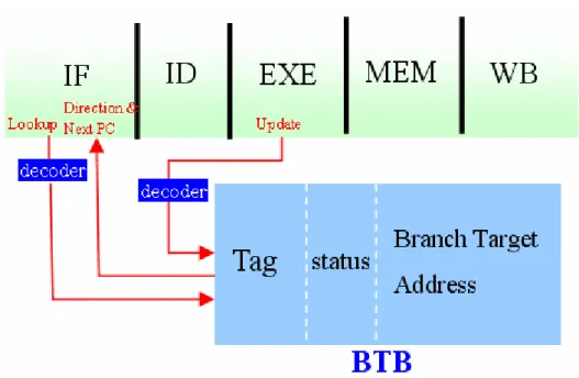
The BTB structure is as showed in fig[4] which is composed of tag field, status field and branch target address field. The status field is composed of valid bit and
predictor bits. Moreover, the high order bits of BTB tag array is equal to the high
Fig. 4 Introduction of BTB
It is usually included read and write operation in BTB. In MIPS five stage
pipelines, each instruction would lookup BTB in IF stage by index part of program
counter to index the corresponding BTB entry. Then, compare the tag part of program
counter to tag field of BTB. The write operation is executed for BTB update in EXE
stage. There would be two situation to update BTB. One is a branch is executed and
its branch information is not in BTB. Another is a branch is executed and its branch
target address is not the same with that in BTB. It would compare the correct branch
target address to the predict branch target address to decide update BTB or not. The
information of valid bit, tag and branch target address would be updated into BTB.
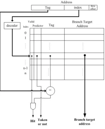
Fig. 5 Structure of direct-map BTB
It constantly has Least Recently Used (LRU)、First-In-First-Out (FIFO) 、
Random and etc. replacement policies in I-Cache and BTB. LRU is replace the entry
least recently used. FIFO is replace the entry put in first. Random is replace the entry
randomly.
1.6 Similar Features of I-Cache and BTB
We could see several similar features of I-Cache and BTB from above
introduction:
1> Each instruction has to access I-Cache and BTB in the first stage of pipeline.
2> Both of them have tag array and the high order bits are the same
BTB, it would be helpful to simplify the operation of BTB access. BTB would save
the area and power consumption because of sharing tag array of I-Cache.
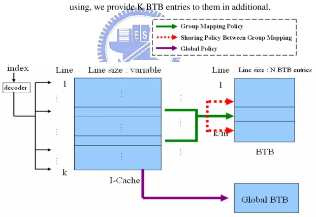
1.7 Our Design
We observe the percentage on each component of BTB power consumption. We
could see that tag array occupy a critical ratio (36%). Above all, we proposed a architecture that BTB could share tag array of I-Cache. In this architecture, the cache
lines in the same index could use N BTB entries. Moreover, under priority
consideration, the cache lines in different index could sharing use the BTB entries
belong to each cache lines. For the branch instructions that still have no empty BTB
entry using, we provide K BTB entries to them in additional.
In BTB operation, we discuss it in three parts - identification、placement and
replacement. Identification – how is a entry found if the information is in the BTB.
Placement – possible places to place. Replacement – when BTB miss occurred, which
BTB entry is replaced ?
Simulation results show that we could reduce as much as 42% percent in dynamic power consumption and 24%in static power consumption with compared to independent BTB of ARM-A8.
Chapter 2.
BACKGROUND & RELATED WORK
2.1 Related Work on Low Power BTB
There are many researches focus on reducing BTB power consumption and they
could be separated into four parts roughly:
1. In reducing dynamic power consumption of BTB, it saves the number of lookup
BTB which is unnecessary because it is every cycle to lookup BTB originally.
2. In reducing dynamic power consumption of BTB, it could reduce the access
power components of every BTB access.
3. In reducing static power consumption of BTB, it could configure the entry
number of BTB to save static power directly but it is possible to affect the
branch prediction accuracy.
4. In reducing both dynamic and static power consumption of BTB, the branch
prediction accuracy of BTB will affect the dynamic and static power
consumption of total system because it affects the performance of system.
Our low power I-Cache-based BTB will involve 2,3,4 parts.
2.2 Related Work on I-Cache Based BTB
Johnson[2] proposed a structure that BTB could share with tag array of I-Cache. The structure is showed as Fig[6]. Each cache line maps to one BTB entry and the structure of I-Cache has no different. Each BTB entry is composed of instruction
number, BTB status and branch target address. The function of instruction number is
as like the line offset part of program counter to identify the branch information is
Fig. 6 Johnson's BTB
Johnson’s BTB structure has advantages and disadvantages. The advantage is it
reduced the tag array to related small instruction number array of BTB. The one
disadvantage is that each cache line only maps to one BTB entry, hence there could
have contention for the single BTB entry while closely spaced branches. Another
disadvantage is that there would be contention between instruction fetching and
branch updating. But this disadvantage could be solved by adding a I-Tag buffer to
save the previous N executed instruction tag.
Flynn[3] made a research on performance comparison between Johnson’s BTB and independent BTB. The important result shows that a infinite Johnson’s BTB with
cache line size of eight instructions could perform about as well as a independent
2.3 Energy Consumption Analysis of BTB
E = access_count × access_energy + static_power × execution_time (AC) (AE) (SP) (ET)
The energy equation of typical BTB is showed as equation. AC is the access
count of BTB. AE is once access energy of BTB and it is composed of index decoding,
tag comparison and branch target address access. SP is static power of BTB and it is
composed of status array, tag array and branch target address array. ET is the
execution time of total system.
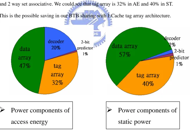
We observe the percentage on each components of AE and SP. We take BTB of
ARM-A8 for example and use the Wattch[8] power library. The BTB is 512 entries and 2 way set associative. We could see that tag array is 32% in AE and 40% in ST.
This is the possible saving in our BTB sharing with I-Cache tag array architecture.
Fig. 7 Power components
Moreover, we compare the energy consumption of Johnson’s BTB and
¾
Power components of
static power
¾
Power components of
a> Because Johnson’s BTB share I-Cache tag array, the AE and SP of
Johnson’s BTB is less than that of independent BTB.
b> Because the branch prediction accuracy of Johnson’s BTB is not as well
as that of independent BTB, the AC and ET of Johnson’s BTB is larger
than that of independent BTB.
From above mentioned, we could see that there would be benefit to save power
consumption of BTB by reducing AE and SP only under no influence of AC and ET.
Thus, our research objective is proposed a low power I-Cache-based BTB by
improving the branch prediction accuracy of architecture-- I-Cache tag array sharing
for BTB. We not only maintain the access count and execution time of low power
I-Cache-based BTB about the same with that of independent BTB but also reduce the
Chapter 3.
DESIGN
In section 3.1, we would discuss how to maintain the branch prediction accuracy
of low power I-Cache-based BTB about the same as that of independent BTB. We
provide three policies to improve branch prediction accuracy – Group Mapping,
Sharing Policy and Global BTB.
Group Mapping –the cache lines in the same index could use N BTB entries
Sharing policy –under priority consideration, the cache lines in different index
could sharing use the BTB entries belong to each cache lines.
Global BTB –For the branch instructions that still have no empty BTB entry
using, we provide K BTB entries to them in additional.
Fig. 8 System Overview
In section 3.2, under consideration of performance and power, we would discuss
the operations of low power I-Cache-based BTB in three sites – identification,
3.1 Mapping method between Cache line and BTB entry
At first, we dynamically observe average number of branch instruction per cache
line in benchmark of Mibench[6]. We could see that 65% of each cache line is zero number of branch instruction, 18% of each cache line is one branch instruction and
16% of each cache line is more than two branch instructions. The number of branch
instruction in each cache line is fairly unbalanced during total execution time. This is
the key point how to utilize BTB entry effectively in this section.
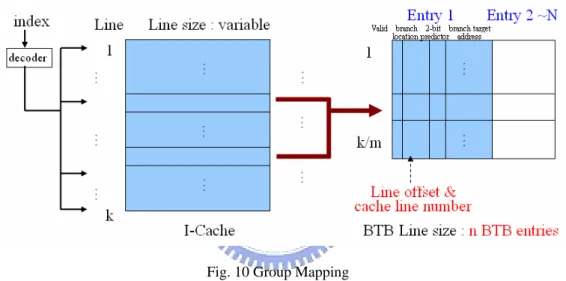
3.1.1 Group
Mapping
The function of group mapping is that the branch instructions in M number of
cache lines could use N number of BTB entries. That is the branch instructions in a
cache line group could us a BTB entry group (mapped BTB entry group). A cache line
group is composed of M number of cache lines. A BTB entry group is composed of N
number of BTB entries. In this policy, each branch instruction of each cache line
could use N number of mapped BTB entries that is each BTB entry could be used by
the branch instruction of M number of mapped cache lines.
Fig. 10 Group Mapping
The principle that how we choose the dedicated cache lines to be a cache line
group is based on the theory of temporal and spatial locality. We choose the cache
lines in the most far distance of address space to be a cache line group that is compose
the cache lines which reference time are the most long to be a cache line group.
Then, the cache lines in a cache line group would have less probability to happen
contention of using BTB entry at any time point.
However, there are different methods to compose a cache line group in different
I-Cache organization. It has Set-based method and Way-based method. Set-based
Way-based method is compose the cache lines in the same way to be a cache line
group first.
In set-associative I-Cache, the cache lines in the same set would have less
probability to be referenced at any time point. Thus, it has higher priority to adopt
set-based method in set-associative I-Cache (Fig[12]). In direct-map I-Cache, way-based method is the only and suited group method. Because we adopt the cache
lines in the distance of (I-Cache line number)/(cache line number of a cache line
group) to be cache line group, the cache lines in a cache line group would be the most
fat distance . Thus, it has higher priority to adopt way-based method in direct-map
I-Cache (Fig[13]). group line cache of number line Cache line Cache I of Number Direct_map ance Group_Dist way Cache I of Number ative Set_associ ance Group_Dist − = • − < •
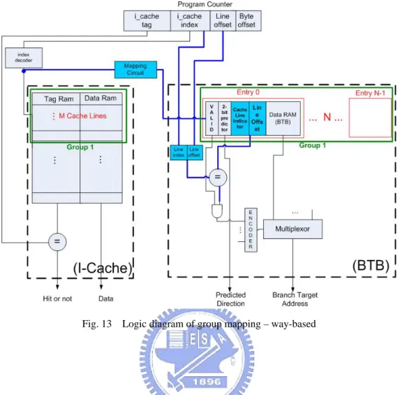
Fig. 13 Logic diagram of group mapping – way-based
The key point of following is how to use the least to achieve the function of
group mapping. Under the feature of I-Cache tag array share for BTB, the structure of
low power I-Cache-based BTB is showed as fig[12]. There is no difference in cache structure while in BTB each BTB entry is composed of valid bit, line offset, cache
line indicator and branch target address. We reduce the tag array and add a line offset
array and a cache line indicator array. The function of cache line indicator is identify
each BTB entry is used by which cache line of mapped cache entry group and the size
of cache line indicator is log(size of cache line group).
The content of cache line indicator is different in set-based method and
way-based method. In set-based method, it have priority to identify each entry is used
cache line indicator is set-number in priority. The source of set-number is part of
program counter and the source of way-number is the result that tag comparison of
each way in I-Cache.
The operation of cache access is parallel to the operation of BTB access. The
operation of cache access is no different. The operation of BTB access is showed as
following. First, we get the cache index by the index part of program counter decoded
from index decoder of I-Cache. We could find out the corresponding BTB entry group
through the mapping circuit and cache index (Fig[14] ). The input of mapping circuit re enable lines of decoded cache index. The output are the enable lines of mapped
BTB entry group. The function of mapping circuit is mapping the cache index to the
mapped BTB entry group. Second, when the tag comparison operation in I-Cache, the
line offset of program counter and way-number are simultaneously compared to the
line offset array and cache line indicator of BTB. Thus, it could identify if hit in BTB
or not. Last, when it choose the instruction by the result of tag comparison in I-Cache,
it also choose the branch target address by the result of line offset and cache line
Group mapping policy has the advantages and disadvantages. The first advantage
is promoting the mapping flexibility between cache lines and BTB entries to solve
every kind of demands. The another advantage is there a better utilization of the BTB
entry in group mapping than the limit mapping of one cache line map to one BTB
entry while the BTB entry is the same. Because of the unfixed branch number of each
cache line, the BTB entry group could be used by the all cache lines of mapped cache
line group. It increases more possible cases for utilization than the one cache line
maps to one BTB entry. While the disadvantage is the access power is direct
proportion to the entry number of BTB entry group because it need to access more
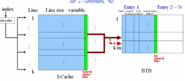
3.1.2 Sharing
Policy
The mapping between cache line and BTB entry promote to a cache line group
maps to a BTB entry group in group mapping policy. Moreover, we want to promote
the utilization of BTB entry further. Thus, we propose the second policy – Sharing
policy.
Sharing policy, under the condition of priority, is each cache line group could
sharing use the BTB entry group mapped by other cache line group (shared BTB entry
group). Besides, the access operation of BTB would include access shared BTB entry
group only when the information of branch instruction belong to the mapped BTB
entry group is located in shared BTB entry group. In sharing policy, each BTB entry
group could be used by more than one cache line group that is each cache line group
could use more than one BTB entry group.
Fig. 16 Logic diagram of sharing policy
Here would introduce how to decide which cache line groups could sharing BTB
entry group to each other. The principle is to find the cache line groups would have
less probability to be referenced at the same time point to sharing BTB entry group.
That has less probability to happen contention of using BTB entry. Based on the
theory of temporal and spatial locality, the cache line groups in distance of (number of
cache line group)/(number of sharing) is the most far distance and which have less
probability to be referenced at the same time point.
The key point of following is how to use the least hardware to achieve the
function of sharing policy. It has different considerations on the sites of cache line and
BTB entry. The consideration on the site of cache line is if it can identify there are any
information of the instructions in the shared BTB entry group. The basic policy is to
propose two methods to identify if it needs to compare with shared BTB entry in each
instruction cycle.
Lookup shared BTB entry group policy:
1. Line based
If the information with any one instruction of the cache line located in the shared
BTB entry group, the whole accesses of the cache line have to compare with the
shared BTB entry group. This policy has the smallest hardware overhead because
we only need to add one bit in each cache line to identify if compare with shared
BTB entry group. But it has the most dynamic access power because the whole
access of the cache line need to compare with shared BTB due to one or more
information with the instructions of cache line in shared BTB entry group and
because each instruction has to add the bits to record the corresponding location.
But this has the smallest dynamic access power because it can point the location
exactly to compare with the location or no compare.
Fig. 18 Lookup policy - instruction based
The consideration on the site of BTB entry is how to identify the BTB entry is
used by which cache line group. To solve this problem we add the Be shared bits to
identify the BTB entry is used by which cache line group and the bit number is
log(shared number + 1)
In order to identify each BTB entry is used by which cache line group, it has to
add a sharing circuit (fig[19]). The input of sharing circuit is be-shared-bit and enable from mapped cache line or enable from shared cache line. The output of sharing
Fig. 19 Sharing circuit
However, we have some special design under the limit of access timing. It has to
complete the comparison of BTB entry in one cycle but it has near to one cycle to
read the lookup shared BTB entry group information and it needs one cycle to
compare with shared BTB entry. The lookup of sharing BTB entry group would not
be completed in one cycle. Thus, in our design, each read lookup shared BTB entry
information is for next instruction using and each first access of each cache line has to
3.1.3 Global
BTB
Global BTB is aimed at the branch instructions still could not have empty BTB
entry using to additional provide K number of BTB entries for them. Besides, the
access operation of BTB would include access global BTB only when the information
of branch instruction belong to the mapped BTB entry group is located in global BTB.
The global BTB is as like typical BTB with fully associative and it has tag field, valid
field and branch target address field. The entry number is less because the branch
instructions still could not have empty BTB entry are less.
Fig. 20 Global BTB
The following is aimed at how to use the least hardware to achieve the function of
Global BTB. We have to add a search global bit to identify each BTB access
including global BTB or not. The methods as mentioned in sharing policy are
Line-based and Instruction-based.
However, for the line-based method and instruction-based method in sharing
policy and global BTB, we have two assumption under the limit of access timing. The
limit of access timing is that has to complete the comparison of BTB entry in one
would not be completed in one cycle. Thus, the two consumption:
a> Each read lookup shared BTB and global BTB information is for next
instruction using
b> Each first access of each cache line has to compare with mapped and shared
BTB entry group and global BTB
Fig. 21 Logic diagram of Low Power I-Cache based BTB
The key point of following is how to use the least hardware to achieve the two
consumption. For the first point, we add two bit register to be the temp of the read
3.2 BTB management:
How to manage the low power I-Cache-based BTB is another important issue.
Different management policy would have different branch prediction accuracy and
power consumption. We discuss this issue in three parts:Identification、Placement 、
Replacement
3.2.1 Identification
The objective of identification is how to find the corresponding BTB entry if the
information of instruction is in BTB. First, it found the corresponding cache line by
the index decoding with the program counter belonged to I-Cache. The next step is
decided to lookup which BTB entry of mapped, shared BTB entry group or global
BTB. This step is based on the two lookup methods-- line based, instruction based, to
decided to lookup which BTB entry. While the data for comparison are different, line
offset and cache line indicator are compared in mapped and shared BTB entry group
and tag field is compared in global BTB. Last step is choosing the exact branch
Fig. 23 Logic diagram of Low Power I-Cache based BTB
3.2.2 Placement
It is to determine the possible location to place branch information in placement
policy. The sequence of possible location is based on the power consumption of
identification to beginning place in the location with smallest power consumption.
The degree with power consumption of identification, when global BTB entry is
larger than BTB entry group, the first placement location is the mapped BTB entry
group and the next is shared BTB entry group, the last is global BTB.
Besides, to avoid the cache line group who have no mapped BTB entry using, we
make the priority of the mapped cache line group higher than the shared cache line
Fig. 24 All cases of placement
A = Mapped BTB entry group full or not
B= Shared BTB entry group full or not
C= Global BTB full or not
D= Mapped BTB entry group shared using or not
I0= Use Mapped BTB entry Group
I1= Use Shared BTB entry Group
I2= Use Global BTB I3= LRU Policy
A B C D Output
0 x x x
1 0 x x
1 1 x 1
1 1 0 0
1 1 1 0
I
0I
1I
0I
2I
33.2.3 Replacement
When there are no empty BTB entries to place, we have to replace one BTB entry.
We want to find out the least recently used BTB entry as the replaced entry in mapped,
shared and global BTB . Thus, we adopt the replacement policy - LRU(Last-Recently
Chapter 4.
EVALUATION
4.1 Evaluation metrics
We evaluate our design by comparing the power consumption of I-Cache based
BTB to that of independent BTB. The power consumption of each is divided into
dynamic power and static power. Each has different power components as showed in
(Fig[26]) which will be each items when measure the power consumption. We would apart dynamic power from static power in the result and then discuss each proportion
of the power components to see the power consumption in different policies.
E
BTB= Dynamic energy + Static energy
E
ICBTB= Dynamic energy
n+ Static energy
n+ Over_head
nincluded six parts – automotive and industrial control, consumer devices, office
automation, network, security, telecommunications
4.3 Evaluation methodology and result
In order to evaluate our low power I-Cache based BTB if promote the branch
prediction accuracy and still keep its low power feature, we compare our design to the
ARM cortex – A8 microprocessor.
In the reference[7] we could know the BTB of A8 is 512 entries, but there is no data about the associative. Thus, we simulate the power and energy representation in
different size and associative to find out the case with lowest energy consumption(as
showed in fig[29]). We could see that the BTB with 512 entries 2way has the lowest energy consumption. We will compare the energy consumption of ICBTB to this case
and our evaluation result will be normalized to base line. We assume that each
dynamic energy and static energy is 50% of total energy.
Notation:
Name example: 4to1-s2-g4 4 cache lines to 1 BTB entry
sharing number = 2 BTB entry groups global BTB size = 4 entries
0 0.2 0.4 0.6 0.8 1 1.2 1.4 1.6 pred . accu racy exec ution tim e total_p ower Dyna mic_p ower Static _powe r total_e nerg y Dyn amic_ ener gy Static_ energ y 256_1 256_2 256_4 512_1 512_2 512_4 1024_1 1024_2 1024_4 2048_1 2048_2 2048_4
Fig. 29 Power Consumption of Different Configuration in A8 microprocessor
First, we see the result of group mapping. The size of cache line group is 1~4
cache lines and BTB entry group are 1~4 BTB entries. The group method is set-based.
We could see that the best case is 4to3 (Fig[30]). Total energy consumption could reduce 18%. The prediction accuracy of 4to3 is 94.75 and that of base line is 94.42.
Fig. 30 Total energy consumption of group mapping
Fig. 32 Power consumption of group mapping
Second, we want to see if sharing policy could reduce more power consumption.
Thus, we take case 4to2 and 4to3 to compare. Because case 4to2 has less entry
number than 4to3 and the branch prediction accuracy is worse than 4to3. If using
sharing policy could let the case of less entry achieve the performance, it would
possible to save more power consumption.
After adopting sharing policy, we could see that 4to2-s2 could perform the
branch prediction accuracy – 94.63% , about as well as that of base line as showed in
fig[33]. Although the peak dynamic power is more than base line, but the total energy is much less than base line. It could reduce 28% of total energy- 38% in dynamic
energy and 18% in static energy. Using sharing policy could promote the utilization of
Fig. 33 Total energy consumption of sharing policy
.
Fig. 35 Power consumption of sharing policy
Third, we want to see if sharing policy could reduce more power consumption.
As mentioned above, we take case 4to2 and 4to3 to compare.
After adopting Global, we could see that 4to2-g8 could perform the branch
prediction accuracy – 94.89%, better than that of base line as showed in fig[36]. Although the peak dynamic power is more than base line, but the total energy is much
less than base line. It could reduce 27% of total energy- 35% in dynamic energy and
19% in static energy. Using global BTB could promote the utilization of BTB entry
Fig. 36 Total energy consumption of global BTB
Fig. 38 Power consumption of global BTB
Last, we want to see if sharing policy and global BTB could work together to
reduce more power consumption. As mentioned above, we take case 4to2 and 4to3 to
compare.
When adopting sharing policy and global BTB together, we could see that the
case 4to2-s1-g1 could perform the branch prediction accuracy – 94.63%, better than
that of base line as showed in fig[39]. It could reduce 33% of total energy- 40% in dynamic energy and 26% in static energy. It reduced more energy consumption than
sharing policy and global BTB alone. This is because the function of sharing policy
Fig. 39 Total energy consumption of sharing policy + global BTB
consumption while the less dynamic power consumption. This is because of the
different hardware overhead and functionality.
Fig. 43 Power consumption of different lookup policy
We compared different distance and number with sharing policy to observe the
branch prediction accuracy. (Fig[44,45]) The size of each cache line group is one cache line and the size of each BTB entry group is one BTB entry. The result is
closely meet with the theory of temporal and spatial locality. We can find that the
branch prediction accuracy is direct proportion to the distance when I-Cache is direct
map while the branch prediction accuracy is high in the same set when it is set
Chapter 5.
CONCLUSION & FUTURE WORK
5.1 Conclusion
We propose the low power I-Cache based BTB which branch prediction accuracy
could be nearly close to the branch prediction accuracy of independent BTB. The low
power I-Cache-based BTB reduced the dynamic and static power consumption of
index decoder and tag array which are the power components of independent BTB. In
the case 4to2-s1-g2 which branch prediction accuracy perform as well as that in
independent BTB of ARM-A8 and which could save 42% in dynamic power consumption and 24% in static power consumption most.
Sharing distance and BTB entry utilization is related to the configuration of
I-Cache. According to the theory of temporal and spatial locality, we inference the
optimized share distance is different with the configuration of I-Cache.
¾ Direct map I-Cache: share distance = [(line number of I-Cache)/ 2] ¾ Set associative I-Cache: share distance < (way number of I-Cache)
According to the theory of spatial locality, we inference the optimized share
distance is different with the configuration of I-Cache. The optimized share distance
of I-Cache with direct map is [I-Cache set number/2] and I-Cache of set associative is
[1 ~ (way number -1)]. And the three kinds of lookup policies would result in
5.2 Future work
The I-Cache based BTB could easily employ the available policy which is
designed for I-Cache to save power consumption of both I-Cache and BTB. We take
the famous drowsy I-Cache[4] and instruction buffer[5] for example. The drowsy I-Cache policy could be easily employed on I-Cache based BTB because the structure
would not affect the policy. And the drowsy effect will save static power of both
I-Cache and BTB. Utilizing the idea of instruction buffer to fetch information of
I-Cache based BTB into a buffer will reduce both fetch power of I-Cache and lookup
power of BTB.
And we have focus on the high way I-Cache which is CAM-RAM structure to
consider the I-Cache based BTB. Because of different structure and features –
low-way I-Cache and high-way I-Cache, there would be different considerations on
Chapter 6.
REFERENCES
[1]. Dharmesh Parikh, Kevin Skadron, Yan Zhang, Student Member, IEEE, and
Mircea Stan, ”Power-Aware Branch Prediction: Characterization and Design”, IEEE
Transactions on Computers, Vol. 53, No. 2, February 2004.
[2]. William Johnson, “Super-Scalar Processor Design”, Technical Report NO.
CSL-TR-89-383, Computer Systems Laboratory, Stanford University, June 1989
[3]. Brian K. Bray and M. J. Flynn, “Strategies for branch target buffer”, ACM press,
1991
[4]. Krisztian Flautner, Nam Sung Kim, Steve Martin, David Blaauw, Trevor Mudge,
“Drowsy Caches: Simple Techniques for Reducing Leakage Power”, Proceedings of
the 29th Annual International Symposium on Computer Architecture (ISCA’02), IEEE
2002
[5]. Jayapala, M.; Barat, F.; Vander Aa, T.; Catthoor, F.; Corporaal, H.; Deconinck, G,
“Clustered loop buffer organization for low energy VLIW embedded processors”,
Jayapala, M.; Barat, F.; Vander Aa, T.; Catthoor, F.; Corporaal, H.; Deconinck, G.;
Computers, IEEE Transactions on Volume 54, Issue 6, Jun 2005
[6]. MR Guthaus, JS Ringenberg, D. Ernst, TM Asutin, T. Mudge and RB Brown,
“MiBench: A free, commercially representative embedded benchmark suite”, Proc.
IEEE 4th Annual Workshop on Workload Characterization, pp. 3-14, Austin, TX,
December 2001
[7]. “Architecture and Implementation of the ARM Cortex –A8 Microprocessor”,
2005 ARM Limited
[8]. G. Contreras, M. Martonosi, J. Peng, R. Ju, and G. –Y. Lueh, “XTREM: A Power
on Languages, Compilers, and Tools for Embedded Systems, Washington DC, USA,
pp. 115-125, June 2004.
[9]. Robert Jones, “Modeling and design techniques reduce 90 nm power”;
(http://www.eetimes.com)
[10]. Rob Pelt, Martin Lee,”Low-Power Software-Defined Radio Design Using