國 立 交 通 大 學
電子工程學系電子研究所
博 士 論 文
以正交頻分多工技術為基礎的低複雜度
無線基頻收發器之研究
Study on Low-Complexity OFDM-Based
Wireless Baseband Transceiver
研究生 : 劉軒宇
指導教授 : 李鎮宜博士
低複雜度無線基頻收發器之研究
Study on Low-Complexity OFDM-Based
Wireless Baseband Transceiver
研 究 生: 劉軒宇 Student: Hsuan-Yu Liu 指導教授: 李鎮宜博士 Advisor: Dr. Chen-Yi Lee
國立交通大學
電子工程學系電子研究所
博士論文
A Dissertation
Submitted to Department of Electronics Engineering & Institute Electronics College of Electrical and Computer Engineering
National Chiao Tung University in Partial Fulfillment of Requirements for the Degree of Doctor of Philosophy
in
Electronics Engineering July 2006
以正交頻分多工技術為基礎的低複雜度
無線基頻收發器之研究
研 究 生: 劉軒宇 指導教授: 李鎮宜教授 國立交通大學電子工程學系電子研究所摘要
在本論文中我們將提出一個結合低複雜度同步器與頻道等化器之以正交頻分多工 技術 (OFDM)為基礎的無線基頻收發器。在現有的 54Mb/s 無線區域網路 (WLAN) 設 計中OFDM 基頻處理器的功率消耗相當可觀,約為 200mW 以上,佔物理層 (PHY) 設 計功率的35%以上。而當系統進展到 480Mb/s 超寬頻 (UWB) 時,功率消耗將會隨著速 度再度提升,因此低功率設計成為高速基頻收發器的關鍵技術。而在現有 OFDM 收發 器中,同步器與頻道等化器需要大量硬體複雜度來求得發射器與接收器之間的訊號偏移 和無線頻道衰減,而共佔了 OFDM 設計裡約 75%以上的邏輯閘數目與功率消耗,因此 如何設計低複雜度的同步器與頻道等化器遂成為我們低功率 OFDM 收發器上的研究重 點。 在本論文中,首先在54Mb/s WLAN 應用上,我們提出一個同步器設計其包含一個 僅使用高能量訊號之自相關計算器 (Auto-correlator; AC) 與一個僅使用高能量係數之匹 配濾波器 (Matched filter; MF)。不同於以往之同步器,我們提出之設計僅使用原信號或 係數中高能量的部分,以降低訊號量和運算量,因此同步器中的乘法次數與暫存器尺寸 可以縮減。我們所提出之設計可以在每個封包 (Packet) 裡減少整個基頻收發器 16.3%的 乘法次數(等同於 3160 次)。而另外在頻道等化器中,為了減少多路徑頻道衰減下達到 10%封包錯誤率 (Packet Error Rate)所提高之 SNR,並在低硬體複雜度下對抗都普勒 (Doppler) 效應造成的時變性頻道,我們採用頻率軸上最小方均錯誤之頻道等化設計 (Frequency-Domain Minimum Mean-Square-Error Channel Equalization; FD-MMSE EQ)並化設計可有效對抗多路徑頻道與減低目前廣泛使用之直接除法式等化器(Direct-Division Equalization)的效能損失。我們所提出之 DDCT 其包含 2 個複數乘法器來追蹤頻道的變 化。它可降低在室內多路徑頻道和都普勒效應環境下5dB~15dB 的頻道偵測的方均誤差 (Mean-square-error)。 在480Mb/s UWB 應用上,我們提出一個同步器設計其包含一個以次取樣為基礎之 AC 與不需使用 Moving-Average 的 MF。我們所提出的設計不只減少乘法次數,還能減 少因應於 UWB 之平行架構的硬體複雜度。與一般採用 4 倍平行度與 132MHz 時脈頻 率以達到528Msamples/s 資料處理速度之同步設計相比,我們提出的設計在同樣 132MHz 時脈頻率下僅需要1 倍平行度以及 1/4 的運算。因此同步設計僅需 4 倍平行設計的 37.6% 的邏輯閘數目與43.3%的功率消耗。在頻道等化器方面,為了消除造成大功率消耗之複 數乘除法器,我們提出一個不使用複數乘除法器的頻道等化器,完全以加減法器代替原 有的乘除法器。與一般等化器相比,我們所提出之設計僅需48.6%的邏輯閘數目與 40.4% 的功率消耗,並在標準8%封包錯誤率上僅增加 0.3dB 的 SNR 誤差。 最後基於我們所提出的低複雜度設計,可應用於以 OFDM 為基礎的 WLAN 、以
LDPC-COFDM 為基礎之 UWB 、以及多頻帶 OFDM 為基礎之 UWB 的基頻收發器已
經在0.18µm 與 0.13µm CMOS 製程上完成設計與測試。他們可以達到 6~480Mb/s 的高
傳輸速率並且在 AWGN 頻道下達到比系統需求好 6.45~9.7dB 的 SNR 效能,而在
11~121-tap 多路徑頻道下也可滿足系統效能需求。我們設計的應用於 54Mb/s WLAN 之 OFDM 收發器的功率消耗是 68mW。而應用於 480Mb/s UWB 之 OFDM 收發器的功率消
耗在0.18µm 與 0.13µm CMOS 製程下分別是 162mW 與 31.2mW。在 UWB 設計中我們
提出的低複雜度同步器與頻道等化器可以減少整個 OFDM 收發器 45.3%的邏輯閘數目
Study on Low-Complexity OFDM-Based
Wireless Baseband Transceiver
Student: Hsuan-Yu Liu Advisor: Chen-Yi Lee Department of Electronics Engineering and Institute of Electronics,
National Chiao-Tung University
Abstract
In this thesis we propose Orthogonal Frequency Division Multiplexing (OFDM)-based baseband transceivers comprising the low-complexity synchronizer and channel equalizer schemes. In the 54Mb/s Wireless Local Area Network (WLAN), the existing OFDM baseband chips consumes > 200mW power, which occupies > 35% power of existing Physical Layer (PHY) system. When the system migrates to 480Mb/s Ultra-Wide Band (UWB), the baseband power will furthermore grow following the raised circuit speeds. Hence the low-power design becomes the key technique of a high-speed baseband transceiver. In OFDM transceiver, the synchronizer and channel equalizer require high hardware complexity to acquire signal offsets between transmitter and receiver and to solve the wireless channel fading, therefore occupying > ~75% gate-count and power of OFDM design. Hence the low-complexity synchronizer and channel equalizer schemes are focused in our research work.
In this paper, first we propose a synchronizer comprising high-power-signal-used auto-correlator (AC) and high-power-coefficient matched filter (MF) for OFDM-based WLAN system. Different from the existing synchronization algorithm, the proposed synchronizer only uses partial high-power signal and coefficients therefore reducing the amount of used signal and computations. Hence the multiplication amount and register size can be efficiently reduced. Equivalent to 16.3% of complex multiplications (equal to 3160) of the WLAN OFDM baseband transceiver can be reduced. For reducing the increased SNR for
Doppler effect with low cost, we employ a frequency-domain minimum mean-square-error channel equalization (FD-MMSE EQ) and propose a decision-directed channel tracking (DDCT). The employed FD-MMSE EQ can efficiently reduce the SNR loss caused by conventional direct-division equalization scheme. The proposed DDCT comprising only 2 complex multipliers is used to track the channel variance. In the indoor multipath channel with Doppler effect the proposed DDCT can reduce the mean-square-error of channel estimation by 5dB~15dB.
For 480Mb/s OFDM-based UWB, we proposed a synchronizer comprising sub-sampling-based AC and moving-average-free MF. The proposed synchronizer not only needs fewer multiplications but also needs lower hardωware cost. A general synchronizer needs 4-parallelsim to achieve 528Msamples/s throughput rate with 132MHz clock rate. The proposed synchronizer only needs 1-parallelsim and 1/4 of computations therefore needing 37.6% gate count and 43.3% power of the general synchronizer. Then we propose a divider-and-multiplier-free channel equalizer where the original complex divider and multipliers are completely replaced by adders and subtractions. It only needs 48.6% gate count and 40.4% power of a general OFDM channel equalizer, and the added SNR loss for typical 8% packet error rate is only 0.3dB.
The baseband transceivers comprising the proposed low-complexity designs are implemented for OFDM-based WLAN, low-density-parity-check (LDPC)-COFDM-based UWB, and multi-band (MB)-OFDM-based UWB systems with 0.18µm and 0.13µm CMOS process. They can achieve 6~480Mb/s high data rates and better 6.45~9.7dB SNR than system performance requirements. The power of the proposed OFDM transceiver for 54Mb/s WLAN is 68mW in 0.18µm CMOS process. And the power of the proposed OFDM transceivers for 480Mb/s UWB is 162mW in 0.18µm CMOS and 31.2mW in 0.13µm CMOS process. The
proposed low-complexity synchronizer and equalizer can reduce 45.3% gate-count and 65.1% power of the UWB OFDM transceiver.
誌謝
在 Si2 實驗室從大三專題到博士畢業的 9 年時光是我求學過程中最美好的回憶, 非 常感謝我的指導教授李鎮宜博士, 他創造了非常完善的研究環境, 使我們有機會從系統 的層面與全方位的角度來思考研究的方向, 他待人處世的優雅態度一直是我們學生效仿 的對象與學習的目標, 他關心學生的生活, 在研究與人生的方向上不斷給我們建議和鼓 勵, 使我們能在如沐春風的環境下漸漸的成長茁壯。感謝實驗室的學長姐與同學: 許騰 尹學長、許騰仁學長、鍾經哲學長、張錫嘉學長、方信雄學長、李有山學長、謝百舉學 長、彭文孝學長、陳寶龍學長、王中正學長、林淑慈學姊、蔡尚峰、劉益全、曾順得、 戴元邦、張偉信、洪健仁、陳黎峰、林昱偉、林建青。他們會在我迷失方向經常提供有 益的建言,也不斷地關心我的生活,使我能有精神上的依靠而不斷奮鬥下去。感謝與我一 同研究的學弟妹: 陳俊吉、魏弘國、俞壹馨、游瑞元、張瑋哲、陳林宏、廖婉君、楊美 慧。在學弟妹的幫忙下,我的研究成果才能夠如此豐碩美好。 在我的博士生涯中見證了實驗室研發的茁壯與成長,大家把一個個關鍵模組漸漸構 建成完整的系統,經歷博士班的訓練使我的思考模式與眼光能更加的廣闊。也非常感謝 我的家庭能夠一直給予我支持,使我能完成博士的學業,最後感謝口試委員的指導與寶 貴意見。CONTENTS
PAGE
Chapter 1: Introduction ... 1
1-1 Thesis Motivation ... 1
1-1-1 Motivation of Low-Complexity Synchronizer for WLAN System... 3
1-1-2 Motivation of Low-Complexity Channel Equalizer for WLAN System... 6
1-1-3 Motivation of Low-Complexity Synchronizer for UWB System ... 7
1-1-4 Motivation of Low-Complexity Channel Equalizer for UWB System ... 9
1-2 Thesis Outline ... 10
Chapter 2: OFDM Systems and Channel Model... 11
2-1 OFDM-Based WLAN System ... 11
2-2 MB-OFDM-Based UWB System ... 19
2-3 LDPC-COFDM-Based UWB System... 26
2-4 Channel Models of WLAN and UWB systems ... 30
2-4-1 Multipath Channel and Doppler Effect of WLAN and UWB systems ... 32
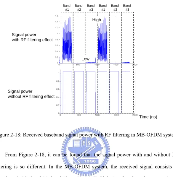
2-4-2 Baseband to Passband Conversion and RF Filtering... 38
2-4-3 Carrier Frequency Offset and Carrier Phase Noise ... 42
2-4-4 Sampling Clock Offset ... 47
2-4-5 AWGN Channel ... 50
Chapter 3: Low-Complexity Design for OFDM-Based WLAN System ... 52
3-1 Low-Complexity Synchronization for OFDM-Based WLAN System... 53
3-1-1 Synchronization Block Diagram for OFDM-Based WLAN System ... 54
3-1-2 General Auto-Correlation-Based PD ... 56
3-1-3 Proposed High-Power-Signal-Used Auto-Correlation for PD... 57
3-1-4 General Auto-Correlation-Based CFO Estimation ... 60
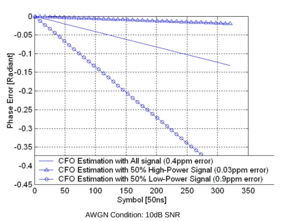
3-1-5 Proposed High-Power-Signal-Used Auto-Correlation-Based CFO Estimation ... 63
3-1-6 General Matched-Filter-Based FWD... 64
3-1-7 Proposed High-Power-Coefficient-Used Matched-Filter for FWD ... 66
3-2 Low-Complexity Channel Estimation for WLAN System ... 68
3-2-1 Basic Channel Equalization with Phase Error Tracking... 68
3-2-4 Proposed Weighted-Average Phase Error Tracing with Pilot Pre-compensation .... 83
3-3 Performance Analysis of Low-Complexity Design for OFDM-Based WLAN System . 91 3-3-1 Performance of the Proposed Low-Complexity Auto-Correlation... 91
3-3-2 Performance of the Proposed Low-Complexity Matched Filter ... 97
3-3-3 Performance of the Proposed DDCT and MMSE EQ ... 100
3-3-4 Performance of the Proposed WAPET ... 104
3-4 Floating-Point PER for OFDM-Based WLAN System ... 107
Chapter 4: Low-Complexity Design for OFDM-Based UWB System... 113
4-1 Low-Complexity Synchronization for OFDM-Based UWB System ... 114
4-1-1 Synchronization Block Diagram of OFDM-Based UWB System ... 115
4-1-2 The Proposed Data-Partition-Based Auto-Correlation ... 120
4-1-3 Data-Partition-Based and Moving-Average-Free Matched Filter ... 123
4-1-4 The Proposed Dynamic-Threshold Design... 125
4-2 Low-Complexity Channel Equalization for UWB System... 126
4-2-1 Basic Divider-Based Channel Equalization with WAPET ... 126
4-2-2 The Proposed Divider-and-Multiplier-Free Channel Equalizer ... 133
4-3 Performance Analysis of Low-Complexity Designs for OFDM-Based UWB System 136 4-3-1 Performance of the Proposed Sub-sampling-Based Auto-Correlation and Matched Filter ... 137
4-3-2 FER and PER Analysis of the Proposed Dynamic-threshold design for UWB System ... 140
4-3-3 CE MSE and PER Analysis of the Proposed Divider-free Channel Equalization. 143 4-4 System Performance of LDPC-COFDM-Based UWB System and MB-OFDM-Based UWB System... 145
4-4-1 PER of LDPC-COFDM-Based UWB System... 145
4-4-2 PER of MB-OFDM-Based UWB System ... 151
Chapter 5: Hardware Architecture and Baseband Chip Design ... 156
5-1 Hardware Design for OFDM-Based WLAN System ... 157
5-1-1 Fixed-point Performance of WLAN system... 157
5-1-2 Hardware Architecture of the Proposed Designs for WLAN System ... 166
5-1-3 Complexity Analysis of the Proposed Designs for WLAN System ... 173
5-2-1 Fixed-point Performance of OFDM-Based UWB Systems ... 181
5-2-2 Hardware Architecture of the Proposed Designs for OFDM-Based UWB Systems ... 190
5-2-3 Complexity and Power Analysis of the Proposed Designs for OFDM-Based UWB Systems... 198
5-2-4 Proposed Baseband Chip for LDPC-COFDM-Based UWB System ... 204
5-2-5 Proposed Baseband Chip for MB-OFDM-Based UWB System ... 208
Chapter 6: Conclusions and Future Work ... 214
References ... 218
Appendix A: Supplementary of OFDM-Based System SPEC... 224
A-1: System Parameter Derivation ... 224
A-2: Power Spectrum Density Requirement... 227
A-3 RF Band Allocation, Spreading Scheme, and Overcoming Jamming Technique of MB-OFDM System ... 228
A-4: Conversion Scheme from Zero-Pad to Cyclic-Prefix in OFDM-Based UWB Systems ... 232
LIST OF FIGURES
PAGE
Figure 1-1: Power of 54Mb/s WLAN designs ... 2
Figure 1-2: Percentages of hardware complexity of OFDM transceiver for WLAN system... 3
Figure 1-3: FER and PER of existing approaches for OFDM-based WLAN system... 4
Figure 1-4: Computation of the general auto-correlation and matched filter ... 5
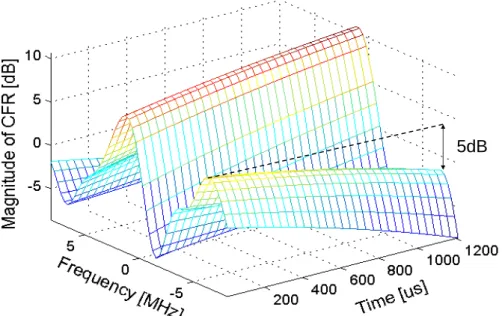
Figure 1-5: Time-variant channel frequency response for WLAN system. ... 6
Figure 1-6: FER and PER of LDPC-COFDM-based UWB system... 8
Figure 1-7: FER and PER of LDPC-COFDM-based UWB system... 8
Figure 2-1: Packet format of IEEE 802.11a system... 14
Figure 2-2: Data OFDM symbol format of IEEE 802.11a system... 15
Figure 2-3: Block diagram of IEEE 802.11a WLAN system... 17
Figure 2-4: Block diagram of IEEE 802.11a baseband system... 18
Figure 2-5: Block diagram of baseband and RF for MB-OFDM-based UWB system... 21
Figure 2-6: Packet format of MB-OFDM-based UWB system ... 23
Figure 2-7: OFDM symbol format of MB-OFDM-based UWB system... 23
Figure 2-8: Block diagram of MB-OFDM baseband system... 25
Figure 2-9: Packet format of LDPC-COFDM-based UWB system... 28
Figure 2-10: Block diagram of MB-OFDM baseband system... 29
Figure 2-11: Block diagram of the channel model for single-band wireless system ... 31
Figure 2-12: Block diagram of the channel model for multipath-band wireless system ... 31
Figure 2-13: Examples of impulse response of IEEE multipath channel ... 34
Figure 2-14: Examples of frequency response of IEEE multipath channel ... 35
Figure 2-15: Examples of CM channel impulse response... 37
Figure 2-16: Examples of CM channel frequency response ... 37
Figure 2-17: A simple example to up-convert the signal from baseband to passband ... 39
Figure 2-18: Received baseband signal power with RF filtering in MB-OFDM system ... 41
Figure 2-19: A LPF of UWB RF receiver ... 42
Figure 2-21: Signal distortion with CFO of 20ppm and 0.4ppm of 5GHz ... 46
Figure 2-22: Phase noise spectrum of CFO model ... 46
Figure 2-23: An example of oversampled signal with clock offset... 48
Figure 2-24: Frequency-domain signal distortion caused by 20ppm clock frequency offset .. 49
Figure 2-25: SER with the proposed AWGN generation method ... 51
Figure 3-1: Block diagram of baseband synchronization for OFDM-based WLAN system... 55
Figure 3-2: Preamble format of IEEE 802.11a system ... 55
Figure 3-3: Example of the auto-correlation power of the packet detection... 57
Figure 3-4: Short symbol power and noise power with 3dB SNR... 58
Figure 3-5: Auto-correlation power of high-power and low-power signal ... 59
Figure 3-6: An example of phase error after CFO estimation in WLAN system... 62
Figure 3-7: Phase error of CFO estimation with all signal, high-power signal, and low-power signal ... 63
Figure 3-8: An example of matched filter power ... 65
Figure 3-9: The long symbol power and AWGN power in average 3dB SNR. ... 66
Figure 3-10: Example of the matched filter power of high-power and low-power coefficients ... 67
Figure 3-11: Example of estimated CFR and true CFR with 50ns RMS and 10dB SNR... 70
Figure 3-12: Example of detected phase error in OFDM-Based WLAN system ... 71
Figure 3-13: Data MSE of perfect EQ schemes... 76
Figure 3-14: Example of time-variant CFR with 50Hz Doppler frequency ... 79
Figure 3-15: Block diagrams of DDCT with feedforward and feedback compensation... 82
Figure 3-16: Incorrect phase detection when the phase error exceeds ±π ... 84
Figure 3-17: Weighting Factors of PET designs ... 87
Figure 3-18: Block diagram of the proposed non-linear WAPET... 88
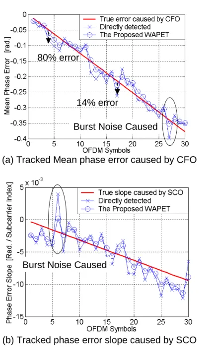
Figure 3-19: Tracked (a) mean and (b) slope of the phase error caused by 0.1ppm residual CFO and 40ppm SCO during 30 OFDM symbols ... 89
Figure 3-20: Tracked phase error of WAPET with and without pilot pre-compensation... 90
WLAN system... 93
Figure 3-23: 6Mb/s PER of the proposed low-complexity auto-correlation... 94
Figure 3-24: 54Mb/s PER of the proposed low-complexity auto-correlation... 94
Figure 3-24-2: FER and CFO estimation error with ω = 8 ... 96
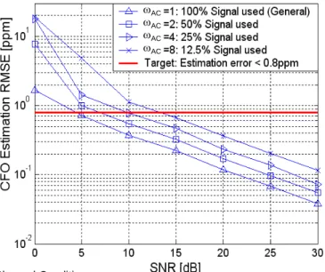
Figure 3-24-3: CFO estimation RMSE and range for OFDM-based WLAN system ... 96
Figure 3-25: CFO estimation RMSE and range for OFDM-based WLAN system ... 97
Figure 3-26: FER of the proposed low-complexity MF for OFDM-based WLAN system... 98
Figure 3-27: 6Mb/s PER of the proposed low-complexity MF in AWGN channel ... 99
Figure 3-28: 6Mb/s PER of the proposed low-complexity MF in IEEE multipath channel with 50ns RMS delay spread... 99
Figure 3-29: Mean Square Error of CE and CT schemes with 0Hz Doppler frequency... 101
Figure 3-30: Mean Square Error of CE and CT schemes with 50Hz Doppler frequency... 102
Figure 3-31: PER of 6Mb/s in IEEE multipath channel with 0Hz Doppler frequency... 103
Figure 3-32: PER of 6Mb/s in IEEE multipath channel with 50Hz Doppler frequency... 104
Figure 3-33: PER of 54Mb/s in IEEE multipath channel with 50Hz Doppler frequency... 104
Figure 3-34: 6Mb/s PER of the proposed WAPET ... 105
Figure 3-35: 54Mb/s PER of the proposed WAPET ... 106
Figure 3-36: PER of perfect synchronization in AWGN channel ... 108
Figure 3-37: PER of the proposed design in AWGN channel... 108
Figure 3-38: PER of perfect synchronization in multipath channel... 110
Figure 3-39: PER of the proposed design in multipath channel ... 111
Figure 3-40: SNR loss for 10% PER of OFDM-based WLAN system ... 112
Figure 4-1: Preamble structure of OFDM-based UWB system ... 116
Figure 4-2: Data flow of synchronization for OFDM-based UWB system ... 117
Figure 4-3: Auto-correlation power used for packer detection in UWB system... 118
Figure 4-4: Auto-correlation phase used for CFO estimation in UWB system ... 118
Figure 4-5: Received signal power used for band detection ... 119
Figure 4-6: Sum of two continuous auto-correlation results for PTD of UWB system... 120 Figure 4-7: Normalized auto-correlation power in (a) better channel and (b) worse channel122
Figure 4-8: Matched-filter power in (a) better channel and (b) worse channel ... 125
Figure 4-9: Example of estimated CFR and true CFR with 5ns RMS and 10dB SNR in 528MHz UWB system ... 128
Figure 4-10: Example of detected phase error in 528MHz UWB system ... 129
Figure 4-11: Tracked phase error caused by (a) 1pm residual CFO and (b) 40ppm SCO during OFDM symbols ... 131
Figure 4-12: Block diagram of the general channel equalizer ... 132
Figure 4-13: Example of (a) constellation and (b) phase probability of the received QPSK symbols... 133
Figure 4-14: Block diagram of the proposed divider-and-multiplier-free channel equalizer 134 Figure 4-15: FER with different ω values of the proposed auto-correlation and matched filter ... 137
Figure 4-16: CFO RMSE with different ω values of the proposed auto-correlation ... 138
Figure 4-17: PER of 120Mb/s with different ω values of the proposed design ... 139
Figure 4-18: PER of 480Mb/s with different ω values of the proposed design ... 139
Figure 4-19: PER of 480Mb/s with different ω values of the proposed design ... 141
Figure 4-20: FER with different threshold of PTD in the multipath channel ... 141
Figure 4-21: PER with different threshold of PTD in 120Mb/s data rate ... 143
Figure 4-22: CE MSE of the proposed channel equalizer... 144
Figure 4-23: PER of proposed channel equalizer in 480Mb/s for MB-OFDM ... 144
Figure 4-24: PER of LDPC-COFDM-Based UWB system in AWGN channel... 146
Figure 4-25: PER of LDPC-COFDM-Based UWB system in multipath channel ... 147
Figure 4-26: SNR loss for 8% PER of OFDM-based WLAN system in AWGN channel... 149
Figure 4-27: PER vs. transmission distances of LDPC-COFDM system ... 150
Figure 4-28: PER of MB-OFDM-Based UWB system in AWGN channel ... 152
Figure 4-29: PER of MB-OFDM-Based UWB system in CM multipath channel... 153
Figure 4-30 (a): PER vs. transmission distance of 200Mb/s and 480Mb/s... 155
Figure 4-30 (b): PER vs. transmission distance of 110Mb/s... 155
Figure 5-3: Block diagram of the proposed fixed-point WLAN baseband system... 161
Figure 5-4: PER of fixed-point WLAN design in AWGN channel... 162
Figure 5-5: PER of fixed-point WLAN design in multipath channel with RMS=50ns... 163
Figure 5-6: Architecture of the auto-corrugators for OFDM-based WLAN system... 167
Figure 5-7 Design of high-power signal selector and gate... 167
Figure 5-8: Signal behavior of the auto-correlators ... 168
Figure 5-9: Architecture of the matched filters for OFDM-based WLAN system ... 169
Figure 5-10: Architecture of the proposed channel equalizer ... 170
Figure 5-11: Architecture of the proposed WAPET ... 171
Figure 5-12: System architecture of the proposed IEEE 802.11a baseband processor... 177
Figure 5-13: Chip microphoto of OFDM-based WLAN baseband processor ... 177
Figure 5-14: Percentages of hardware complexity of OFDM transceiver for WLAN system ... 179
Figure 5-15: 480Mb/s PER with different wordlength setting for LDPC-COFDM system .. 182
Figure 5-16: 480Mb/s PER with different wordlength setting for MB-OFDM system... 182
Figure 5-17: Block diagram of the fixed-point baseband design for UWB system... 184
Figure 5-18: PER of fixed-point LDPC-COFDM-based UWB system... 184
Figure 5-19: PER of fixed-point MB-OFDM-based UWB system... 185
Figure 5-20: PER vs. transmission distances of fixed-point LDPC-COFDM-based UWB system... 187
Figure 5-21: PER vs. transmission distances of fixed-point MB-OFDM-based UWB system ... 188
Figure 5-22: Architecture of auto-correlators for 528MS/s OFDM-based UWB systems .... 191
Figure 5-23: Architecture of matched filters for 528MS/s OFDM-based UWB systems... 193
Figure 5-24: Example of signal in the three kinds of the matched filter... 194
Figure 5-25: Architectures of the channel equalizers for UWB system... 196
Figure 5-26: Architecture of the logarithm-based arc-tangent design... 198
Figure 5-27: System architecture of the proposed baseband processor for OFDM-based UWB systems ... 205 Figure 5-28: Chip microphoto of the proposed LDPC-COFDM-based UWB baseband
processor... 206
Figure 5-29: Percentage of gate-count and receiver power of the OFDM transceiver for LDPC-COFDM-based UWB ... 209
Figure 5-30: Stages of clock buffers of OFDM transceiver... 210
Figure 5-31: Chip microphoto of MB-OFDM OFDM transceiver ... 212
Figure 5-32: Power percentage of MB-OFDM UWB baseband transceiver ... 213
Figure A-1: Power spectrum mask of IEEE 802.11a WLAN system ... 228
Figure A-3: Band location of IEEE 802.15.3a OFDM-based UWB system... 230
Figure A-4: An example of MB hopping of MB-OFDM-based UWB system ... 230
Figure A-5: An example of jamming happening in UWB bands ... 231
Figure A-6: An example of received OFDM symbols with jamming ... 232
Figure A-7: The transmitted OFDM signal with cyclic prefix... 232
LIST OF TABLES
PAGE
Table 2-1: Data rate parameters for IEEE 802.11a WLAN system... 12
Table 2-2: OFDM signal parameters for IEEE 802.11a WLAN system... 13
Table 2-3: Central frequencies of RF carriers for IEEE 802.11a WLAN system ... 13
Table 2-4: Required SNR for 10% PER of IEEE 802.11a system ... 16
Table 2-5: CFO and SCO specification of IEEE 802.11a system ... 16
Table 2-6: Power consumption of PHY layer of IEEE 802.15.3a system... 20
Table 2-7: Data rate parameters of MB-OFDM-based UWB system ... 22
Table 2-8: OFDM signal parameters of MB-OFDM-based UWB system... 23
Table 2-9: Performance requirement of MB-OFDM-based UWB system... 24
Table 2-10: Main parameter of LDPC-COFDM-based UWB system ... 27
Table 2-11: Data rate parameter of LDPC-COFDM-based UWB system ... 27
Table 2-12: Required Eb/N0 for 8% PER of MB-OFDM-based UWB system... 29
Table 2-13: Characteristic of Multipath channel for 54Mb/s WLAN and 480Mb/s UWB systems ... 33
Table 2-14: Specification of carrier phase noise ... 47
Table 3-1: Hardware complexity of CE and EQ designs ... 78
Table 3-2: Summary of SNR loss variation of the proposed design ... 107
Table 3-3: SNR for 10% PER of OFDM-based WLAN system in AWGN channel... 109
Table 3-4: SNR for 10% PER of OFDM-based WLAN system in time-variant IEEE multipath channel ... 112
Table 4-1: Summary of SNR loss variation of the proposed design ... 145
Table 4-2: SNR for 8% PER of LDPC-COFDM System in AWGN channel ... 147
Table 4-3: SNR for 8% PER of LDPC-COFDM System in multipath channel... 148
Table 4-4: Transmission distance for 8% PER of LDPC-COFDM System... 151
Table 4-5: SNR for 8% PER of MB-OFDM-Based UWB system in AWGN channel ... 152
Table 4-6: SNR for 8% PER of MB-OFDM-Based UWB system in CM channels ... 153
Table 5-2: Power consumption of DAC and ADC for WLAN system ... 160
Table 5-3: PAPR of the proposed fixed-point design for WLAN system ... 161
Table 5-4: SNR for 10% PER of fixed-point WLAN design in AWGN channel... 163
Table 5-5: SNR for 10% PER of fixed-point WLAN design with RMS=50ns... 164
Table 5-6: SNR for 10% PER of fixed-point WLAN processors in AWGN channel ... 165
Table 5-7: Coefficient index of the matched filter for OFDM-based WLAN system... 170
Table 5-8: Design complexity of the baseband receiver in each packet for OFDM-based WLAN system... 174
Table 5-9: Hardware cost of CE and EQ designs... 176
Table 5-10: Chip summary of OFDM-based WLAN baseband processor ... 178
Table 5-11: Hardware complexity of OFDM-based WLAN baseband processor... 178
Table 5-12: Comparison of baseband power consumption for OFDM-based WLAN system ... 180
Table 5-13: SNR for 8% PER of 480Mb/s UWB with different wordlengths ... 183
Table 5-14: SNR for 8%PER of fixed-point LDPC-COFDM-based UWB system... 185
Table 5-15: SNR for 8% PER of fixed-point MB-OFDM-based UWB system ... 186
Table 5-16: Transmission distances for 8% PER of fixed-point LDPC-COFDM-based UWB system... 188
Table 5-17: Transmission distances for 8% PER of fixed-point MB-OFDM-based UWB system... 189
Table 5-18: PAPR of OFDM-based UWB systems... 189
Table 5-19: Design complexity of a baseband receiver in each packet for OFDM-based UWB system... 200
Table 5-20: Hardware complexity of the proposed synchronizer and general 4-parallelism synchronizer ... 202
Table 5-21: Hardware complexity of the proposed divider-and-multiplier-free channel equalizer and the general divider-based channel equalizer with 4-parallelism... 203
Table 5-21-2: Complexity of the proposed design, magnitude-and-phase-based design, and divider-and-multiplier-based design... 204 Table 5-22: Chip summary of the proposed LDPC-COFDM-based UWB baseband processor
Table 5-23: Hardware complexity of the LDPC-COFDM baseband chip ... 207
Table 5-24: Finite stage machine of the proposed multi-stage gated-clock control... 210
Table 5-25: Chip summary of MB-OFDM OFDM transceiver ... 212
Table 6-1: Complexity reduction and SNR loss changing of the proposed design... 217
Table 6-2: Chip performance and OFDM hardware complexity ... 217
Table A-1: Dominated parameters of OFDM-based WLAN system ... 225
Table A-2: Key parameters of LDPC-COFDM-based UWB system... 226
Table A-3: Key parameters of MB-OFDM-based UWB system ... 226
Chapter 1:
Introduction
1-1 Thesis Motivation
Orthogonal frequency division multiplexing (OFDM) is widely applied in high-speed wireless local area network (WLAN) such as IEEE 802.11a, Hiperlan/2, and IEEE802.11g standards. The OFDM technique is also considered to provide 480Mb/s high-speed wireless transmission for the ultra-wide band (UWB) system [15, 16]. The OFDM technique brings high channel utilization to efficiently achieve high data rate (480Mb/s for UWB) in a limited bandwidth (only 528MHz for UWB) and provides the robustness to solve the wireless multipath channels (multi-tap Rayleigh fading channel) and to enhance system performance (low bit-error-rate and packet-error-rate). However not only the transmission quality but also the power consumption dominates the competitiveness of wireless products. The low-power design can reduce the charging times and extend the lifetime of wireless portable products such as WLAN cards or wireless USB devices. However with the OFDM design the existing baseband processors consume high power as shown in Figure 1-1. The baseband (BB) receiver power is equal to 35%~53% of whole physical-layer (PHY) which comprises of baseband design, ADC/DAC, and analog RF transceiver. Hence developing a low-power OFDM transceiver becomes the main concern for low-power wireless transceiver. When the system migrates from 54Mb/s WLAN to the 480Mb/s UWB system, the low-power concern becomes more important.
100 500 2001 ‘02 ‘03 ‘04 ‘05 ‘06 Power (mW) Year 200 300 ADC RF BB Proposed BB 53% of PHY 35% of PHY
Figure 1-1: Power of 54Mb/s WLAN designs
For keeping the quality of low design power, the power consumption of overall PHY is suggested in multi-band OFDM (MB-OFDM)-based UWB proposals [15, 16]. Those are only 323mW and 236mW in 0.13µm and 90nm CMOS technologies. And in the baseband design, high-parallelism architectures and high clock rates are needed for at least 528Msamples/s throughput rates [1, 2, 5, 30, 41, 45]. With the increased hardware complexity and clock rates, the UWB baseband design power will grow rapidly.
In reference [3], the OFDM modules occupy 83% gate-count and 55% power of the WLAN baseband chip comprising OFDM transceiver and FEC codec. In the OFDM transceiver, not only the noticed FFT/IFFT design, but also the synchronizer and channel equalizer consume high power. The percentage of OFDM receiver power is shown in Figure 1-2. As shown in Figure 1-2, the synchronizer (Sync.) and channel equalizer combining a phase error tracking (PET) totally occupy 75% of gate-count and 80% of OFDM power [3]. And in another existing OFDM transceiver, the channel equalizer even occupies 62.6% gate count [43].
TX (13%) Sync (25%) FFT (10%) Channel Equalizer & PET (50%) Others (<2%) Sync (22%) FFT (18%) Channel Equalizer & PET (58%) Others (<2%)
(a) OFDM gate-count Percentage (total 317K)
(b) OFDM RX power Percentage (total 68mW in 0.18µm CMOS
Figure 1-2: Percentages of hardware complexity of OFDM transceiver for WLAN
system
Hence the power elimination and hardware reduction of synchronizer and channel equalizer is focused in our research topic. However the synchronizer which detects the signal timing and carrier frequency offset (CFO) and the channel equalizer which solves the multipath fading and compensates all remained error caused by CFO and sampling clock offset (SCO) dominate the system performance such as packet error rate (PER) of WLAN and WPAN systems. Hence the challenge of low-power synchronizer and channel equalizer is simultaneously to keep the system performance and efficiently reduce the design power.
1-1-1 Motivation of Low-Complexity Synchronizer for WLAN System
In the WLAN system, the main performance requirement is to ask PER to be lower than 10% to keep the transceiver quality. And the signal-to-noise ratio (SNR) for 10% PER is highlighted as the performance summary [3, 18, 25]. In the baseband system, the synchronizer detects the valid packet and correct symbol timing. It shouldIEEE 802.11a WLAN system, the minimum SNR values for 10% PER belong to 6Mb/s data rate mode [18, 25]. Therefore the FER must be less than the PER of 6Mb/s. In the general synchronization scheme [24, 27, 28, 29, 41], full signal of each FFT symbol in the preamble are used therefore resulting great performance. The FER of the general synchronization scheme and PER of existing baseband chips [3, 18, 25] is shown in Figure 1-3. We can find the general synchronization makes FER greatly lower than the PER curves. So the general synchronization is actually over design, and the performance margin which is between the SNR for 10% FER and SNR for 10% is extended to 2.6dB by the general synchronization.
Channel Condition: AWGN channel, CFO=40ppm+phase noise, SCO=40ppm
[25] [18]
2.6dB
[3]
Figure 1-3: FER and PER of existing approaches for OFDM-based WLAN system
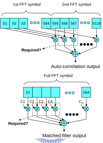
For reducing the synchronizer complexity and keeping system performance, we propose a low-complexity synchronizer with high-power-signal-used (HPSU) auto-correlator and high-power-coefficient-used (HPCU) matched filter. In the synchronizer, the kernel is the auto-correlator and matched filter (i.e. cross-correlation)
31]. The main computation of auto-correlator and matched filter is shown in Figure 1-4. S1 S2 S3 S64 S65 S66 S67 S128 Auto-correlation output 1st FFT symbol 2nd FFT symbol Required? S1 C1 C2 C3 C4 S64 CN Full FFT symbol Required?
Matched filter output
Figure 1-4: Computation of the general auto-correlation and matched filter
As shown in Figure 1-4, there are several complex multiplications for each circuit result. And the multiplications and registers to store the multiplication inputs dominate the synchronizer complexity [28]. But in the proposed synchronizer, only partial signal of each FFT symbol is used therefore reducing multiplications and the registers size. For achieving the nice trade-off between high system performance and low design complexity, the amount of the partial signal is decided according to system simulation results. The proposed synchronization scheme can reduce 74% multiplications of a general synchronizer. And the additional SNR loss for 10% PER
1-1-2 Motivation of Low-Complexity Channel Equalizer for WLAN
System
In OFDM system the accurate channel estimation (CE) with Least Square (LS) equalization (EQ) are widely discussed by existing publications for high performance [27, 52]. However the LS EQ limits the performance of accurate CE, and hence we employ a low-complexity frequency-domain minimum mean-square-error (FD-MMSE) EQ to release the performance bound limited by LS EQ. Based on comparison of simulation performance and design complexity we can find the employed FD-MMSE EQ can achieve better performance improvement with lower design complexity than existing accurate CE approaches. Otherwise in WLAN system, 50Hz of Doppler frequency is assumed for 5km/hr human mobility. Therefore the channel variance is resulted by the Doppler effect. The time-variant channel frequency response (CFR) is shown in Figure 1-5. The channel magnitude varies 5dB magnitude during 1.2ms, equal to a packet length of 6Mb/s rate. In this case the channel tracking (CT) is needed to enhance channel estimation (CE) accuracy and reduce system PER.
Channel Condition: RMS delay = 50ns, Doppler frequency = 50Hz 5dB
In the existing silicon-proven approach, a CT enhances CE mean-square error (MSE) by 2.5dB ~ 3dB with 18 parallel complex multipliers [24]. For achieving higher performance and lower hardware cost, we propose a decision-directed channel tracking (DDCT) scheme. It can efficiently reduce channel error and track channel variance from the error vectors of de-mapping error. The proposed DDCT can enhance CE MSE by 6dB~27dB with only two complex multipliers. And for system PER performance it can reduce 0.9 ~ 1.5dB SNR for 10% PER. The required gate-count is only 60% of the existing WLAN approach [24, 43].
1-1-3 Motivation of Low-Complexity Synchronizer for UWB System
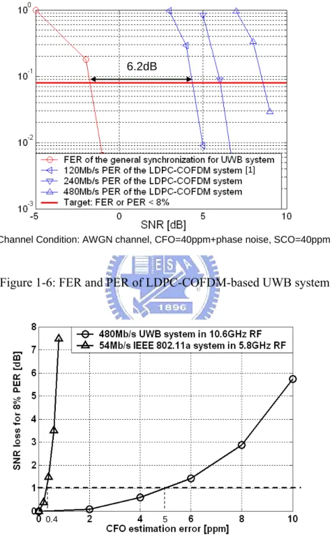
Similar to that in WLAN system, the general synchronizer is also over design in the UWB system. Both the large performance margin in FER and the high tolerance to CFO motivate the low-power synchronizer design. The FER of general synchronization scheme and PER of our developed low-density parity-check (LDPC)-COFDM system is shown in Figure 1-6. The performance margin between SNR for 8% FER and SNR for typical 8% PER is increased to 6.2dB by the general synchronization scheme. And the large performance margin can allow the complexity reduction of a synchronizer. Besides, in UWB system the tolerance of CFO estimation error can be larger than that in WLAN system. The SNR loss for typical 8% PER versus CFO estimation error is shown in Figure 1-7. Since the subcarrier spacing of UWB (4.125MHz) is equal to 13.6 times of that of WLAN (312.5KHz), the tolerance to inter-carrier interference (ICI) which is caused by CFO can be naturally higher in UWB systems. And the PER of UWB system is less sensitive to CFO estimation error.for WLAN system and 5ppm for UWB system. This high tolerance also allows the complexity reduction of a synchronizer.
Channel Condition: AWGN channel, CFO=40ppm+phase noise, SCO=40ppm
[1]
6.2dB
Figure 1-6: FER and PER of LDPC-COFDM-based UWB system
0.4 5
Figure 1-7: FER and PER of LDPC-COFDM-based UWB system
increases the power consumption and hardware cost. For achieving high-performance and low-hardware complexity, we propose a sub-sampling-based auto-correlator and moving-average-free matched filter. The proposed design not only reduces the computation of synchronizer but also reduces the hardware cost of the parallel architecture. The proposed synchronizer can reduce 75% complex multiplications of the general approach. It only needs 38% gate count and 43% power of a general 528MS/s 4-parallelism synchronizer in 0.18µm CMOS process. It reduces equivalent 27% power of the whole OFDM transceiver with <0.2dB additional SNR loss for 8% PER.
1-1-4 Motivation of Low-Complexity Channel Equalizer for UWB
System
With DDCT, the proposed channel equalizer occupies 50% gate count and 58% power of our OFDM-based WLAN transceiver [3]. And the complex divider and complex multipliers occupy total 90% power of the equalizer. When the system migrates to UWB, the packet length is less than 1/10 and the channel variance within one packet is also smaller. And DDCT is not required. However the complex divider and complex multipliers still occupy 60% equalizer power. For QPSK-OFDM-based UWB system [1, 15, 16], we propose a divider-and-multiplier-free channel equalizer. It uses addition/subtraction of symbol phases instead of complex multiplication/division of symbols. The proposed equalizer scheme only needs 52% gate count and 48% power of a divider-and-multiplier-based equalizer in 0.18µm CMOS process. It reduces equivalent 33% power of the OFDM transceiver with 0.3dB additional SNR loss for 8% PER.
1-2 Thesis Outline
In this thesis, the system specifications and simulation channel models for OFDM-based WLAN system, proposed LDPC-COFDM-based UWB system, and MB-OFDM-based UWB system are introduced in chapter 2. The proposed low-complexity synchronizer, low-complexity channel equalizer, design performance analysis, and system simulation results for OFDM-based WLAN system are introduced in chapter 3. The proposed low-complexity synchronizer, low-complexity channel equalizer, design performance analysis, and system simulation results for OFDM-based UWB systems are introduced in chapter 4. The fixed-point simulation, design architectures, hardware complexity and power analysis, and the baseband chip designs for OFDM-based WLAN, LDPC-COFDM-based UWB, and MB-OFDM-based UWB in 0.18µm and 0.13µm CMOS process are introduced in chapter 5.
Chapter 2:
OFDM Systems and Channel Model
In this chapter, the system specification of OFDM-based WLAN and UWB systems will be introduced. The introduced systems comprise IEEE 802.11a WLAN system, multi-band OFDM (MB-OFDM)-based UWB system considered for IEEE 802.15.3a standard institution [15, 16], and the proposed low density parity check (LDPC)-COFDM-based UWB system [1]. And the system parameters, signal format, and system block diagram will be briefly shown. After the introduction of specifications, the practical channel model of wireless systems will be introduced. The introduced important non-ideal impacts comprises multipath fading channel, Doppler effect, carrier frequency offset (CFO), carrier phase noise (CPN), sampling clock offset (SCO), RF filtering, and AWGN. The channel parameters for WLAN and UWB systems and the signal distortion caused by these impacts will be also shown.
2-1 OFDM-Based WLAN System
IEEE 802.11a standard was instituted in December 1999. It is the earliest IEEE WLAN system using OFDM technique for 54Mb/s data rate and 0~100 meter wireless communication. OFDM technique, which separates transmitted signal into several subcarriers, can be robust to overcome the serial inter-symbol interference (ISI) distortion from the complex channels during high data rates and long distances transmission environment. Hence it has been a popular solution in high-speed or broadcasting system such as WLAN, UWB, DVB applications. IEEE 802.11a system
5.15~5.825GHz RF band. The main parameters: system data rates, OFDM signal duration, and RF bands for IEEE 802.11a are listed in Table 2-1~Table 2-3.
Table 2-1: Data rate parameters for IEEE 802.11a WLAN system
Data rate (Mb/s) Signal bandwidth (MHz) Constellation Coding rate (R) Coded bits per subcarrier (NCBPC) Data bits per OFDM symbol (NDBPS) 6 BPSK 1/2 1 24 9 BPSK 3/4 1 36 12 QPSK 1/2 2 48 18 QPSK 3/4 2 72 24 16-QAM 1/2 4 96 36 16-QAM 3/4 4 144 48 64-QAM 2/3 6 192 54 20 64-QAM 3/4 6 216
As listed in Table 2-1, the data rates from 6Mb/s ~ 54Mb/s are generated with BPSK, QPSK, 16-QAM, and 64-QAM of constellation and 1/2 ~ 3/4 of FEC coding in the 20MHz-bandwidth WLAN system. As listed in Table 2-2, the 64-point fast Fourier transformation (FFT)-based OFDM technique is used for baseband modulation. The OFDM symbol period is 4.0µs. It consists of FFT symbol (3.2µs) and guard-interval (0.8µs). The 0.8µs guard-interval (GI) is used for solving the possible ISI in 0~100 meters of transmission distance.
Table 2-2: OFDM signal parameters for IEEE 802.11a WLAN system
Parameter Value
FFT size (N) 64-point
FFT symbol duration (TFFT) 3.2µs
Guard-interval duration (TGI) 0.8µs
OFDM symbol period (TOFDM) 4.0µs
Data subcarriers per OFDM symbol 48
Pilot subcarriers per OFDM symbol 4
Total baseband bandwidth 20MHz
Subcarrier spacing 312.5KHz
Used baseband bandwidth 16.5625MHz
Table 2-3: Central frequencies of RF carriers for IEEE 802.11a WLAN system
Band Carrier Frequency (MHz)
Lower and Middle U-NII Band 5180, 5200, 5220, 5240, 5260, 5280, 5300, 5320
Higher U-NII Band 5745, 5765, 5785, 5805
As listed in Table 2-2, in each OFDM symbol, the number of data subcarriers (NSD) is 48. That means 48 constellation-mapped symbols are transmitted during
4.0µs OFDM symbol. Besides, there are 4 pilot subcarriers in each OFDM symbol. The pilot subcarriers can be used by error-tracking designs of the baseband synchronization of the receiver. As listed in Table 2-3, in the lower and middle U-NII
standard. In the higher U-NII band, there are 4 carriers from 5745MHz to 5805MHz. And each space between two neighbor carriers is 20MHz. According to Table 2-1 and Table 2-2, we can find the data rates are related to signal bandwidth, used data subcarrier number, constellation methods, and FEC coding rate. The data rate calculation of OFDM-based system is discussed in Appendix A-1.
IEEE 802.11a system is using packet-based burst transmission. The packet-based signal format is shown in Figure 2-1. The packet mainly consists of the preamble, the header, and the data OFDM symbols. The preamble and header can efficiently assist the baseband receiver to correctly recover the following data OFDM symbols. The preamble which consists of short and long symbols can be used for automatic gain control (AGC), synchronization, and channel estimation. The header contains the important system parameters such as data rate and data length. The system parameters can assist the receiver to correctly demodulate the received signal. The data OFDM symbols including the transmitted data consists of several OFDM symbols. In IEEE 802.11a system, the typical transmitted data amount is 1000 bytes.
Header Preamble 16µs 4µs @ 6Mb/s 152µs @ 54Mb/s Data OFDM symbols 10 Short symbols and
2 Long symbols
38 OFDM symbols @ 54Mb/s and 1000 data bytes 1 OFDM
symbol
Figure 2-1: Packet format of IEEE 802.11a system
When the data rate is 54Mb/s, the NDBPS is equal to 216 as listed in Table 2-1. So,
data OFDM symbol format is shown in Figure 2-2. It consists of 3.2µs FFT symbol and 0.8µs guard interval. The guard interval is the cyclic prefix of FFT symbol. It’s used to handle the ISI mainly caused by multipath fading channel and assists to the signal behavior of frequency-domain channel equalizer of the receiver.
FFT symbol
3.2µs
0.8µs
Guard
interval
4.0 µs
OFDM symbol period
Figure 2-2: Data OFDM symbol format of IEEE 802.11a system
In the system performance, the standard requirement for IEEE 802.11a is the packet error rate (PER) should be lower than 10%. And the typical transmit data amount per packet is 1000 data bytes. The maximum SNR value to achieve 10% PER is listed in Table 2-4 [18, 25]. That means that the SNR to achieve 10% PER can not exceed the constraints. The specification of CFO and SCO effects of IEEE 802.11a system is listed in Table 2-5. The ±20ppm CFO of RF frequency from 5180MHz to 5805MHz listed in Table 2-3 will be equal to ±116.1KHz. The ±20ppm SCO will cause the time-domain signal drift and frequency-domain signal rotated. Hence the time-domain synchronization and frequency-domain phase error tracking (PET) is needed in OFDM system [9, 10, 11, 12, 13, 14]. The other system requirement: power spectrum density is discussed in Appendix A-2.
Table 2-4: Required SNR for 10% PER of IEEE 802.11a system
Data Rate (Mb/s) SNR for 10% PER (dB)
6 9.7 9 10.7 12 12.7 18 14.7 24 17.7 36 21.7 48 25.7 54 26.7
Table 2-5: CFO and SCO specification of IEEE 802.11a system
Effect Range
Carrier Frequency Offset (CFO) ±20ppm
Sampling Frequency Offset (SCO) ±20ppm
The block diagram of the WLAN system is shown in Figure 2-3. The media access control (MAC) which links to software part is used to allocate channel bands and control the transmission and receiving commends. The baseband design is used to develop the correct signal format and solve the channel effects. And it links to RF with digital-to-analog converter (DAC) and analog-to-digital converter (ADC). The RF is used to up-convert and down-convert the signal between 20MHz baseband and 5180MHz~5805MHz passband. It also amplifies and filters the signal to satisfy the
system requirement. MAC Baseband RF Wireless Channel Transmitted data Digital modulated signal DAC Software (PC) Analog modulated signal MAC Baseband RF Demodulated data Digital received signal ADC Software (PC) Analog received signal Transmitter Receiver Antenna Antenna
Figure 2-3: Block diagram of IEEE 802.11a WLAN system
For the system requests to baseband design, the baseband design comprises the complete transmitter including FEC encoder and QAM-OFDM modulator and the receiver including the synchronization, QAM-OFDM demodulator, and FEC decoder. The block diagram of IEEE 802.11a baseband system is shown in Figure 2-4. As shown in Figure 2-4, the transmitter consists of the FEC encoder, QAM mapping, IFFT, guard-interval insertion, preamble insertion, shaping filter, and peak-to-average power ratio (PAPR) clipping. They are used to satisfy the system specification containing data rates, signal format, and power spectrum mask. The peak-to-average power ratio (PAPR) injuring the linearity of RF power amplifier (PA) is also suppressed by the clipping design.
Timing-drift model Timing-drift model Timing Sync. Timing
Sync. FrequencySync. Frequency
Sync.
Channel Estimation
Channel
Estimation decoderViterbi
Viterbi decoder FFT FFT FEC encoder FEC
encoder IFFTIFFT
Guard-interval insertion Guard-interval insertion QAM mapping QAM mapping I Q AGC AGC Preamble Insertion Preamble
Insertion clippingPAPR PAPR clipping Shaping filter Shaping filter I Q Multipath channel Multipath channel CFO channel CFO channel AWGN model AWGN model VGA model VGA model Data in Phase error tracking Phase error tracking Sampling phase control Sampling phase control Guard-interval removal Guard-interval removal QAM demapping QAM
demapping interleaver
De-interleaver scrambler De-scrambler Transmitter Receiver Channel model Data out
Figure 2-4: Block diagram of IEEE 802.11a baseband system
And then the data is sent to the channel model. The channel model consists of timing-drift model, multipath channel model, AWGN model, CFO model, and VGA model. They are used to simulate the RF and wireless channel effects. We can find the non-ideal impacts containing SCO, multipath fading, CFO, RF thermal noise, and the variant gain amplification (VGA) effect of the RF receiver. And then the channel signal is sent to the baseband receiver. The baseband receiver is used to estimate and then compensate the RF and channel effects. And then the data can be demodulated and then sent to the MAC. In the initial, the AGC is used to correct the RF VGA gain. It makes the swing level of RF output signal match to the ADC range. And then the timing synchronization, sampling phase control, and frequency synchronization are used to detect the packets distorted by channel effects, and to solve the SCO and CFO distortion. After synchronization, the most channel effect of received signal can be eliminated. And then the data is sent to from FFT to de-scrambler to finish the
of IEEE 802.11a baseband system can be correctly finished.
2-2 MB-OFDM-Based UWB System
UWB system is promoted by industry from 2002. It provides 480Mb/s high data rate in 528MHz wide bandwidth and 0~10 meter transmission distance. The high-speed UWB system is instituted by IEEE 802.15.3a working group. In the standard institution, there are two techniques considered for 480 Mb/s high-speed UWB systems. The first one is direct sequence (DS)-UWB system. This system is promoted by Motorola and Freescaler. Its advantage is using direct sequence spread spectrum (DSSS) technique to solve the large jamming power which causes -8dB signal-to-interference ratio (SIR) from a satellite [15]. And the DS-UWB system has the feature of low design complexity. So it’s a nice choose to reduce the time to market. And the industry has developed many ripe DS-UWB systems and relative products. The second main choice of UWB system is multi-band (MB)-OFDM UWB system. It’s promoted by MB-OFDM alliance (MBOA) mainly consists of Intel, TI, and many wireless IC manufacturer. This system consists of timing-frequency-interleaved (TFI) RF hopping and OFDM technique. From OFDM-based WLAN system such as IEEE 802.11a and ETSI HipterLAN/2, OFDM is widely used to solve the complex multipath fading problem for high performance and high speed transmission. In UWB system it’s used to solve the multipath fading with 0~15ns RMS delay spread in 528MHz wide bandwidth. It can also solve the large jamming with MB technique. Different from DS-UWB, the challenge of OFDM circuit is the low-power problem. So low-power is the main concern of OFDM-based UWB system. The predicted power of PHY layer in 130nm and 90nm CMOS process
323mW in 90nm and 0.13µm CMOS process. That will be only 23%~32% of the 54Mb/s WLAN design in 0.25µm CMOS process [23, 44]. Since the power may be increased with data rates and signal bandwidth, the low-power design becomes the main concern of OFDM-based UWB system.
Table 2-6: Power consumption of PHY layer of IEEE 802.15.3a system
Process Data Rate (Mb/s) Transmit Receive CCA (Signal Detect) Power Save (Deep Sleep Mode) 110 93 mW 155 mW 94 mW 15 W 200 93 mW 169 mW 94 mW 15 W 90 nm 480 145 mW 236 mW 94 mW 15 W 110 117 mW 205 mW 117 mW 18 W 200 117 mW 227 mW 117 mW 18 W 130 nm 480 180 mW 323 mW 117 mW 18 W
Different from OFDM-based WLAN system, MB-OFDM system uses MB hopping technique and the spreading method to solve large jamming of from the satellite. The block diagram of baseband and RF design with MB control signal is shown in Figure 2-5. The baseband transmitter should feedforward control the Band ID of RF transmitter. And the synchronization of baseband receiver should detect the band boundary and feedback control the band control signal feedback to RF receiver design. Based on the accurate band detection, the correct baseband signal can be sent. And IEEE 802.15.3a working group defined 5 band groups for MB hopping. The RF
band allocation, baseband spreading scheme, and overcoming jamming technique of MB-OFDM system is supplemented in Appendix A-3.
RF Transmitter Local oscillator DAC Baseband Transmitter Band ID LPF BPF AMP RF Receiver Local oscillator ADC Baseband Receiver Band ID LPF BPF LNA Antenna Antenna
Figure 2-5: Block diagram of baseband and RF for MB-OFDM-based UWB system
The data rate parameters and OFDM signal parameters are listed in Table 2-7 and Table 2-8. With fixed QPSK constellation and 1/3 ~ 3/4 FEC coding rate, 53.3 ~ 480Mb/s data rates can be provided in the 528MHz-bandwidth UWB system. As listed in Table 2-8, the OFDM symbol duration is 312.5ns and the number of used data subcarriers of each OFDM symbol is 100. The derivation of system parameters is also discussed in Appendix A-1.
Table 2-7: Data rate parameters of MB-OFDM-based UWB system Data rate (Mb/s) Signal bandwidth (MHz) Constellation FEC Coding rate (R) Spreading factor (S) 53.3 QPSK 1/3 4 80 QPSK 1/2 4 110 QPSK 11/32 2 160 QPSK 1/2 2 200 QPSK 5/8 2 320 QPSK 1/2 1 400 QPSK 5/8 1 480 528 QPSK 3/4 1
The packet format of MB-OFDM system is shown in Figure 2-6. As shown in Figure 2-6, the preamble consists of 30 OFDM symbols used for AGC, synchronization, and channel estimation. And the Header includes 200 bits of baseband parameter and MAC control signal. The packet all consists of OFDM symbols. The OFDM symbol format is shown in Figure 2-7. As shown in Figure 2-7, the OFDM symbol consists of the FFT symbol and zero pad (ZP). Similar to the guard interval of IEEE 802.11a system, the pre-ZP is used to increase the distance between two FFT symbols to decrease the ISI distortion. And the post-ZP is used for RF hopping after transmitting the FFT symbol. However the guard-interval should be the cyclic prefix in the OFDM system. The detailed scheme to make ZP become cyclic prefix is supplemented in Appendix A-4.
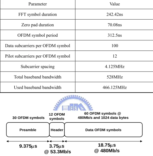
Table 2-8: OFDM signal parameters of MB-OFDM-based UWB system
Parameter Value
FFT symbol duration 242.42ns
Zero pad duration 70.08ns
OFDM symbol period 312.5ns
Data subcarriers per OFDM symbol 100
Pilot subcarriers per OFDM symbol 12
Subcarrier spacing 4.125MHz
Total baseband bandwidth 528MHz
Used baseband bandwidth 466.125MHz
Header Preamble 9.375µs 3.75µs @ 53.3Mb/s 18.75µs @ 480Mb/s Data OFDM symbols 30 OFDM symbols
60 OFDM symbols @ 480Mb/s and 1024 data bytes 12 OFDM
symbols
Figure 2-6: Packet format of MB-OFDM-based UWB system
FFT symbol
242.4ns
60.6ns
9.5ns
Pre-ZP
Post-ZP
According the specification of MB-OFDM system [16], the Eb/N0 constraint and required transmission distance for 8% PER is listed in Table 2-9. And the equivalent SNR values are also listed.
Table 2-9: Performance requirement of MB-OFDM-based UWB system
Data Rate (Mb/s) Transmission distance (meters) Eb/N0 for 8% PER (dB) SNR for 8% PER (dB) 110 10 12.9 7.1 200 4 18.3 15.1 480 2 20.5 21.1
As listed in Table 2-9, the minimum transmission distance of 110Mb/s ~ 480Mb/s main data rates are 10 meters, 4 meters, and 2 meters. It’s found the transmission distance of higher data rate is shorter. That is because in a mode of lower data rate, the spreading method is used so the data correctness is more robust to channel noise. So the SNR to achieve 8% PER can be lower and the tolerated signal power degradation caused by path loss can be higher. Hence the modes of lower data can achieve higher transmission distances. In the specification of CFO and SCO, the parameters are the same as OFDM-based WLAN system. The tolerated CFO and SCO are also ±20ppm. To satisfy the MB-OFDM-based specification, the developed block diagram is shown in Figure 2-8.
From
MAC Data Scrambler encoderFEC QPSK
Frequency-domain Spreading IFFT TX Band Control TX RF Timing offset Multipath channel AGC & Sync. De-Scrambler FEC decoder De-QPSK De-Spreading MB channel equalization RX RF Data RF effects AWGN Transmitter Receiver Channel model To MAC Time-domain Spreading TX signal TX Band ID RX Band Detection RX signal FFT RX Band ID
Figure 2-8: Block diagram of MB-OFDM baseband system
The difference in the baseband designs between MB-OFDM system and OFDM-based WLAN system is the MB-OFDM system contains the spreading/dispreading blocks, band control/detection blocks, and MB channel equalization block. And the transmitter (TX) RF and receiver (RX) RF blocks are also added to simulate the MB hopping effect. In the transmitter, the frequency-domain spreading is used to spread the data subcarriers as the complex symmetric. And the time-domain spreading is used to duplicate the transmitted signal. And when the spreading is used the system is more robust to channel noise and jamming and the data rate will be lower. In the end of baseband transmitter, the TX band control is used to control the band ID and sent it to RF. And then the TX RF will up-convert the transmitted signal to the pass band. In the receiver, the RX band detection is used to detect the band ID with the received signal, AGC signal, and synchronization signal. Since the RX band detection can detect the correct band ID of the received signal, the
domain, since the channel frequency response of different bands will be different, the MB channel equalization needs to estimate all the channel frequency response. The MB channel equalization is used to first estimate the channel response of all used bands and then compensates the received data. After the channel equalization, the channel distortion can be just removed. And then the de-spreading can be just used to recover the transmitted data through frequency-domain and time-domain spreading. And then the data is sent through de-QPSK, FEC decoder, and de-scrambler. Finally it will be sent back to MAC to finish the baseband data flow.
2-3 LDPC-COFDM-Based UWB System
Besides MB-OFDM system, there are many different OFDM-based system for high data rate and high performance UWB application. One of these systems is LDPC-COFDM system. LDPC-COFDM system is using LDPC coding for forward error correction. Different from Convolutional encoding/Viterbi decoding, the LDPC coding is the block code and does not need the use of interleaver. From 2003, we have begun developing the LDPC-COFDM system for UWB and future advanced applications. The main parameters of LDPC-COFDM-based UWB system are listed in Table 2-10.
Table 2-10: Main parameter of LDPC-COFDM-based UWB system
Parameter Value
Signal bandwidth 528MHz
Data rate 120Mb/s, 240Mb/s, 480Mb/s
FFT size 128 point
LDPC code parameter (600, 450) semi-regular code
As listed in Table 2-10, the provided data rates are 120Mb/s, 240Mb/s, and 480Mb/s and the system is based on 128-point FFT and (600, 450) semi-regular LDPC code. In LDPC code, the block length is 600 and the number of message nodes is 450. That means in each 600 bits of LDPC encoder output, there are 450 bits used to transmit data and 150 bits used for error correction of the LDPC decoder. So the FEC coding rate is 450/600 = 3/4. Based on the LDPC coding, the data rate parameters are listed in Table 2-11.
Table 2-11: Data rate parameter of LDPC-COFDM-based UWB system
Data rate (Mb/s) Constellation Coding rate (R) Spreading factor
Average data bits per OFDM symbol
(NDBPS)
120 QPSK 3/4 4 37.5
240 QPSK 3/4 2 75
system, the provided data rates are 120Mb/s, 240Mb/s, and 480Mb/s. The spreading method creates different data rates. Similar to MB-OFDM system, the LDPC-COFDM system also uses frequency-domain spreading methods to increase the robustness to channel noise and the jamming in the transmitted bands. The packet format of LDPC-COFDM system is shown in Figure 2-9.
Header Preamble 9.375µs 2.19µs @ 120Mb/s 18.75µs @ 480Mb/s Data OFDM symbols 30 OFDM symbols
60 OFDM symbols @ 480Mb/s and 1024 data bytes 7 OFDM
symbols
Figure 2-9: Packet format of LDPC-COFDM-based UWB system
The same as the MB-OFDM system, the preamble consists of 30 OFDM symbols. The packet all consists of OFDM symbols and the OFDM symbol format is the same as that of MB-OFDM system. Therefore total 70ns of zero pad to decrease the ISI distortion. After the adding of zero pad in the receiver, the circular convolution of channel impulse response and transmitted signal can be also resulted in the receiver. The Eb/N0 constraint and required transmission distance for 8% PER of LDPC-COFDM system is listed in Table 2-12. Similar to MB-OFDM system, the required transmission distances of 120Mb/s, 240Mb/s, and 480Mb/s are also 10 meters, 4 meters, and 2 meters. To satisfy the system specification and performance requirement of LDPC-COFDM system, the developed baseband block diagram is shown in Figure 2-10.
Table 2-12: Required Eb/N0 for 8% PER of MB-OFDM-based UWB system
Data Rate (Mb/s) Eb/N0 for 8% PER (dB) Transmission distance (meters) 120 12.9 10 200 18.3 4 480 20.5 2 From MAC Data Scrambler LDPC
encoder QPSK Spreading IFFT Preamble insertion Shaping Clipping Timing offset Multipath channel Sync. FFT De-Scrambler LDPC decoder De-QPSK De-Spreading Channel equalizer AGC Data RF effects AWGN Transmitter Receiver Channel model To MAC
Figure 2-10: Block diagram of MB-OFDM baseband system
Since the proposed LDPC-COFDM system is focusing the combination of LDPC coding and OFDM system, the MB hopping of RF technique is not included. It can be found the difference from the existed WLAN and UWB system is using the LDPC encoder and decoder. Based on the system block diagram, the transmitted data can be encoded by LDPC design and modulated by QPSK-OFDM design. After shaping and clipping design, the transmitted signal can satisfy the PSM requirement and RF power
clock offset, multipath channel, RF effects, and AWGN is simulated. In the receiver, first the AGC and synchronization are used to estimate and compensate the channel distortion. And then the received signal can be correctly demodulated. Through the LDPC decoder and de-scrambler, the data can be recovered and finally sent to the MAC.
2-4 Channel Models of WLAN and UWB systems
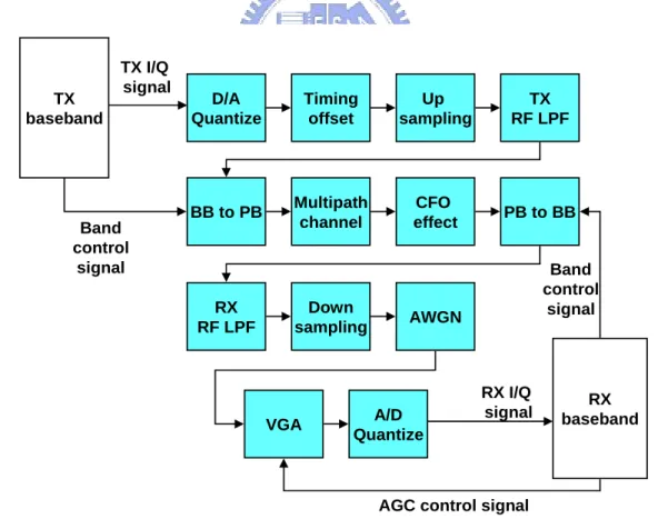
In wireless system, the channel model is developed to simulate the signal distortion caused by wireless environment and RF circuits. In the wide-band and high-speed OFDM-based wireless system, the main channel non-ideal impacts are multipath fading, multi-band hopping for multi-band system, Doppler effect, clock offset, frequency offset, RF filtering effect, and AWGN. The block diagram of channel models for the single-band wireless system and multi-band (MB) wireless system are shown in Figure 2-11 and Figure 2-12. As shown in Figure 2-11, between transmitter (TX) baseband design and receiver (RX) baseband design, there are 9 blocks: D/A quantize, clock offset, TX RF low-pass filter (LPF), multipath channel, CFO effect, RX RF LPF, AWGN, variant gain amplifier (VGA), and A/D quantize. They are developed to simulate the channel distortion of the baseband signal. The Doppler effect which causes time-variant multipath channel is included in the multipath channel block. The band-pass filters (BPF) of RF are converted to parts of LPF of RF. And the VGA block is used to simulate the RF amplification effect and AGC behavior. As shown in Figure 2-12, there are 4 blocks added to the channel model: up-sampling, baseband (BB) to passband (PB) block, passband back to baseband block, and down-sampling.
Timing offset Multipath channel CFO effect RF TX LPF RF RX LPF VGA TX baseband RX baseband D/A Quantize A/D Quantize AWGN TX I/Q signal RX I/Q signal
AGC control signal
Figure 2-11: Block diagram of the channel model for single-band wireless system
Multipath channel RX RF LPF Down sampling CFO effect AWGN A/D Quantize TX baseband RX baseband BB to PB VGA TX I/Q signal RX I/Q signal
AGC control signal Timing offset Up sampling D/A Quantize TX RF LPF PB to BB Band control signal Band control signal