IEEE MICROWAVE AND WIRELESS COMPONENTS LETTERS, VOL. 24, NO. 1, JANUARY 2014 35
Miniaturized and Large-Division-Ratio Ring Coupler
Using Novel Transmission-Line Elements
Kuan-Lin Ho and Pei-Ling Chi, Member, IEEE
Abstract—In this letter, a novel transmission-line element that
is able to exhibit a high-impedance passband is proposed and applied for coupler realization with a large power division ratio. The analysis of the transmission-line element was conducted by its equivalent circuit model and the closed-form equations for the pole and zero frequencies of the effective impedance were derived to help control the passband impedance and phase responses by the lumped parameters. The high-impedance feature of the presented artificial line was exploited to experimentally develop a 12 dB ring coupler, which occupies only 29% footprint of the conventional coupler at 3.5 GHz. Experimental results are in good agreement with the simulation data.
Index Terms—High-impedance lines, large division ratios,
miniaturization, ring couplers.
I. INTRODUCTION
D
IRECTIONAL couplers are one of the most funda-mental components used in the microwave systems. For example, the 3 dB branch-line coupler finds extensive applications in phase shifters, balanced amplifiers, mixers, and antenna/array feeding networks. In some systems where only a small amount of the power is used to drive a sub-circuit, such as the monitoring circuit at the antenna feeding terminal, the coupler’s ability to produce a large power-division ratio is of particular importance. To this end, many approaches have been reported in the literature [1]–[6]. In particular, the coupler prototype made up of the -type transmission lines [2] demon-strates up to 79% size reduction but its power division ratio is limited by the maximum attainable line impedance, typically 150 , with the PCB fabrication technique. Consequently, the short-ended coupled-line sections were incorporated into the networks in [3] to pursue large division ratios at the expense of large footprints. In [4], a 13 dB size-reduced ring hybrid was proposed where the design complexity is increased owing to the need of two distinct approaches to implementing the 90 and 270 high-impedance arms. In addition, the ring coupler comprising the unbalanced composite right/left-handed trans-mission lines [5] or 50- microstrip lines of three particular electrical lengths [6] shows an alternative for high division-ratio realization but a further attempt to enhance the miniaturization factor, which is 56% or 51% herein, may be needed.Manuscript received August 12, 2013; revised October 19, 2013; accepted October 19, 2013. Date of publication November 11, 2013; date of current ver-sion January 06, 2014. This work was supported in part by the National Sci-ence Council of Taiwan under Grant NSC 101-2221-E-009-108 and Grant NSC 102-2221-E-009-029.
The authors are with the Department of Electrical and Computer Engineering, National Chiao Tung University, Hsinchu, Taiwan (e-mail: peilingchi@ nctu. edu.tw).
Color versions of one or more of the figures in this letter are available online at http://ieeexplore.ieee.org.
Digital Object Identifier 10.1109/LMWC.2013.2288261
In this work, a high-impedance transmission-line element is proposed, analyzed, and applied for developing a ring coupler with a 12 dB power-division ratio. This presented coupler is based on the four-section prototype with alternate high- and low-impedance arms [7] and the proposed line structure can be easily designed for arbitrary high impedance with a desired 90 or 270 phase, resulting in considerable size reduction and de-sign simplicity. To realize the prescribed high impedance and phase response at a frequency of interest, the proposed line was implemented by properly tailoring the pole and zero frequencies that control the passband impedance and dispersion character-istics. Thus, the pole and zero frequencies will be analytically derived and studied in terms of the lumped parameters in the equivalent circuit model. A fully planar (via-free) 3.5 GHz ring coupler was experimentally developed and occupies only 29% footprint of the conventional coupler with the circumference of six quarter-wavelengths. Measured and simulated results are in excellent agreement.
II. EQUIVALENTCIRCUITMODELBASEDSYNTHESIS
To engineer the proposed transmission-line element with de-sired frequency behavior, i.e., a high-impedance passband, its effective impedance and dispersion relation are analyzed by means of the equivalent circuit model. Fig. 1 shows the pro-posed line prototype and its corresponding circuit model. In Fig. 1(b), the interdigital capacitor in the center is connected in parallel with a -network, which consists of a thin line loaded by a meander- or straight line and a patch in series connection. In addition, the microstrip lines on both ends contribute to the ladder networks and in the circuit model. The respec-tive lumped-element correspondences are indicated. As shown in Fig. 1(a), the complete circuit model comprises three indi-vidual parts, including the central circuit and the bilateral ladder networks as highlighted by dashed lines. Note that the parasitic effects of the central circuit are considered by and . Thus, the transmission matrix of the overall circuit can be readily ob-tained by matrix multiplication of the cascaded sections as
(1) where Section 1, 2, and 3 are designated in Fig. 1(a). Since the transmission matrices of Section 1 and 3 can be derived straight-forwardly, only that of Section 2 is given as follows:
(2a)
(2b)
36 IEEE MICROWAVE AND WIRELESS COMPONENTS LETTERS, VOL. 24, NO. 1, JANUARY 2014
Fig. 1. (a) Equivalent circuit model and (b) the lumped-element correspon-dence with the geometric structure of the proposed transmission-line element.
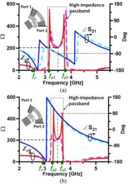
Fig. 2. HFSS (dashed lines) and circuit-model (solid lines) calculated effective impedances and phase responses of the proposed transmission-line elements. (a) The line element of impedance 205.2 and phase at 3.5 GHz. The
extracted lumped parameters are , ,
, , , , .
(b) The line element of impedance 205.2 and phase 90 at 3.5 GHz. The
extracted lumped parameters are , ,
, , , , .
Fig. 3. Variation of the effective impedance with respect to . The other circuit parameters are given as follows: , ,
, , , , .
Thus, the matrix elements , , , and in (1) can be obtained thereafter. For a symmetric single transmission-line section, the effective impedance and the dispersion relation can be found in terms of ( ) and :
(3)
To yield a passband region of desired high impedance, as shown in Fig. 2, the two pole frequencies and , which delimit the passband of interest and thus affect the impedance level, should be analyzed first. Note that and correspond to the frequencies where the dispersion relation and , respectively, and as the name suggests, the effective impedance at either frequency becomes infinite for in (3) given that . Thus, in the passband the desired impedance and phase at the operating frequency can be carried out by a proper choice of the poles and with re-spect to the operating frequency. The closed-form expressions for and are
(4a)
(4b) Assuming that is satisfied around the passband, the parasitic element can be neglected in the initial design phase. Consequently, the pole frequency , rendering a compact form with parameter dependences on , , and . As an important feature to reduce the coupler’s cir-cumference and exhibit design flexibility, the high-impedance sections with out-of-phase relation can be easily carried out based on similar structures by tailoring the poles
for the line and for the 90 line. Thus, the three-quarter-wavelength transmission line can be replaced by the proposed line with a 90 phase lead. Note that when , the phase and group velocities in the passband of the dispersion curve are anti-parallel, which shows the left-handed characteristics [8] and leads to a phase lead ( ); on the other hand, a conventional phase lag is obtained when .
For demonstration purpose, the 205.2- artificial lines of and 90 at 3.5 GHz were developed and characterized by full-wave simulations in Fig. 2(a) and (b), respectively. In practice, in (4) the lumped elements that lead to desired poles are decided first. Small values were designed for capacitances , , and so as to reduce footprint of metal patterns and facilitate fabrication of interdigital capacitors. The determination of the remaining inductances and is much simplified thereafter and large inductance, if necessary, can be easily developed in our structure by increasing the (meander-) length or reducing the line width. Next, the physical prototype was developed where the physical dimensions of each line section were optimized so that its equivalent circuit elements are in close approximation to the design data for the lumped parameters. The circuit-simulated results based on the extracted lumped elements are included in Fig. 2 for compar-ison and are in good agreement. Note that the lumped-element values were obtained by curve fitting method. Moreover, by inspection of (4), the poles and are independent of the parameter , which is then used to control the zero frequency
HO AND CHI: MINIATURIZED AND LARGE-DIVISION-RATIO RING COUPLER USING NOVEL TRANSMISSION-LINE ELEMENTS 37
Fig. 4. Photograph and configuration of the proposed 12 dB ring coupler. Ports 1 and 3 are the – and – ports, respectively. The lumped-element correspon-dence with the geometric structure is indicated. Detailed physical parameters are given in the closed-up insets.
Fig. 5. Measured (dashed lines) and simulated (solid lines) -parameters for the proposed 12 dB ring coupler. (a) The parameters obtained at port 1 ( -port) and (b) the -parameters obtained at port 3 ( - -port).
TABLE I
COUPLERCOMPARISON INTERMS OF THESIZEREDUCTIONFACTOR, POWER
DIVISIONRATIO ,AND THEFABRICATIONTECHNIQUE
(near the passband) so that . Note that is a solution to and may occur in-between frequencies and when , thus deteriorating the high-impedance characteristics. As is varied from 0.6 to 2.6 nH in Fig. 3, the zero can be effectively lowered below , and thus improves the attainable impedance level in the passband region.
III. EXPERIMENTALDESIGN: A 12 B RINGCOUPLER
By taking advantage of the engineerable high-impedance fea-ture from the proposed transmission-line element, a 12 dB ring
coupler operating at 3.5 GHz was developed on a RO4003C substrate with thickness and dielectric constant . Note that by applying the proposed line prototype, a coupler with a higher division ratio is feasible; however, the passband bandwidth will be reduced accordingly. As shown in Fig. 4, the proposed ring coupler was implemented using four transmission-line sections, including two microstrip lines of impedance 51.6 and two 205.2- line elements with the 90 phase lead and phase lag between ports 1 and 4 and between ports 2 and 3, respectively. Thus, the ports 1 and 3 are the difference and sum ports, respectively. For arbitrary power divisions, the specific arm impedances and output power distribution can be referred to [7]. Referring to the physical dimensions in Fig. 4, the proposed coupler can be easily carried out by the uniplanar microstrip technique. The measured and simulated -parameters are depicted in Fig. 5 and are in good agreement. The experimental results at 3.5 GHz are as follows: , ,
, , ,
, . The mea-sured bandwidths for return losses at - and - ports and isolation are 25.7%, 10.5%, and 20.33%, respectively. Furthermore, the bandwidths for magnitude imbalances , , and for phase imbalances are 20.35%, 15.94%, 21.11%, and 25.21%, respectively. The ring coupler has a mean radius of 6.7 mm that demonstrates a 71% size reduction as compared to the conventional coupler with a ring perimeter of at 3.5 GHz. Table I gives the comparison between the proposed work and previous couplers.
IV. CONCLUSION
In this letter, an artificial transmission-line element with engi-neerable high-impedance and phase characteristics is proposed. The line prototype is flexible for design considerations and easy for fabrication (via-free). This feature was applied to implemen-tation of a 12 dB ring coupler.
REFERENCES
[1] C. –Y. Wu, Y. –C. Chiou, and J. –T. Kuo, “Dual-band rat-race coupler with arbitrary power divisions using microwave C-sections,” in Proc.
Asia-Pacific Microw. Conf., Dec. 2009, pp. 2108–2111.
[2] C. -L. Hsu, J. -T. Kuo, and C. -W. Chang, “Miniaturized dual-band hybrid couplers with arbitrary power division ratios,” IEEE Trans.
Mi-crow. Theory Tech., vol. 57, no. 1, pp. 149–156, Jan. 2009.
[3] C. -L. Hsu, “Dual-band branch line coupler with large power divi-sion ratios,” in Proc. Asia–Pacific Microw. Conf., Dec. 2009, pp. 2088–2091.
[4] H. -R. Ahn and S. Nam, “Wideband microstrip coupled-line ring hy-brids for high power-division ratios,” IEEE Trans. Microw. Theory
Tech., vol. 61, no. 5, pp. 1768–1780, May 2013.
[5] P. -L. Chi, “Miniaturized ring coupler with arbitrary power divisions based on the composite right/left-handed transmission lines,” IEEE
Mi-crow. Wireless Compon. Lett., vol. 22, no. 4, pp. 170–172, Apr. 2012.
[6] M. –J. Park and B. Lee, “Design of ring couplers for arbitrary power division with 50 lines,” IEEE Microw. Wireless Compon. Lett., vol. 21, no. 4, pp. 185–187, Apr. 2011.
[7] C. Y. Pon, “Hybrid-ring directional coupler for arbitrary power divi-sions,” IEEE Trans. Microw. Theory Tech., vol. MTT-9, no. 11, pp. 529–535, Nov. 1961.
[8] C. Caloz and T. Itoh, Electromagnetic Metamaterials: Transmission
Line Theory and Microwave Applications. Hoboken, NJ: Wiley,