On the Data Reuse and Memory Bandwidth Analysis
for Full-Search Block-Matching VLSI Architecture
Jen-Chieh Tuan, Tian-Sheuan Chang, Member, IEEE, and Chein-Wei Jen
Abstract—This work explores the data reuse properties of
full-search block-matching (FSBM) for motion estimation (ME) and associated architecture designs, as well as memory bandwidth re-quirements. Memory bandwidth in high-quality video is a major bottleneck to designing an implementable architecture because of large frame size and search range. First, memory bandwidth in ME is analyzed and the problem is solved by exploring data reuse. Four levels are defined according to the degree of data reuse for pre-vious frame access. With the highest level of data reuse, one-access for frame pixels is achieved. A scheduling strategy is also applied to data reuse of ME architecture designs and a seven-type classifi-cation system is developed that can accommodate most published ME architectures. This classification can simplify the work of de-signers in designing more cost-effective ME architectures, while si-multaneously minimizing memory bandwidth. Finally, a FSBM ar-chitecture suitable for high quality HDTV video with a minimum memory bandwidth feature is proposed. Our architecture is able to achieve 100% hardware efficiency while preserving minimum I/O pin count, low local memory size, and bandwidth.
Index Terms—Architecture, block matching, memory
manage-ment, motion estimation, video coding.
I. INTRODUCTION
M
OTION estimation has been widely employed in the H.26x, MPEG-1, -2, and -4 video standards [1] to exploit the temporal redundancies inherent within image frames. Block matching is the most popular method for motion estimation (ME). Numerous pixel-by-pixel difference operations are central to the block matching algorithms and result in high computation complexity and huge memory bandwidth. Owing to the rapid progress of VLSI technology, computation complexity requirements can easily be fulfilled by multiple PE’s architecture, even for large frame sizes and frame rate. However, without enough data, these PEs can hardly be fully utilized and simply result in increased silicon area. The data rate is limited by available memory bandwidth. There-fore, straightforward implementation of ME is an I/O bound problem rather than a computation-bound one. The memoryManuscript received December 15, 1999; revised October 22, 2001. This work was supported by the National Science Council of the Republic of China under Contract NSC87-2215-E009-039. This paper was recommended by As-sociate Editor I. Ahmad.
J.-C. Tuan is with the iCreate Technologies Corporation, Science-Based Industrial Park, Hsinchu 300, Taiwan, R.O.C. (e-mail: [email protected]. edu.tw).
T.-S. Chang is with the Global Unichip Corporation, Science-based Industrial Park, Hsinchu 300, Taiwan, R.O.C. (e-mail: [email protected]).
C.-W. Jen is with the Department of Electronics Engineering, National Chiao Tung University, Hsinchu 300, Taiwan, R.O.C. (e-mail: cwjen@ twins.ee.nctu.edu.tw).
Publisher Item Identifier S 1051-8215(02)01122-9.
bandwidth problem may be solved by careful scheduling of the data sequence and setting up appropriate on-chip memories. Meanwhile, a well-designed ME architecture reduces the requirements of memory bandwidth and the I/O pin count, but still maintains high hardware efficiency.
Many algorithms and hardware have been dedicated to ME. The full-search block-matching (FSBM) algorithm is one these algorithms, and searches through every candidate location to find the best match. To reduce the computational complexity of FSBM, various fast algorithms were proposed [2]–[7], [19] that searched fewer points. However, these fast algorithms suffer from irregular control and lower video quality, and thus FSBM remains widespread owing to its simplicity, regularity, and superior video quality. Many architectures have been proposed for implementing FSBM. These architectures use systolic array [8]–[11], tree structure [12], or 1-D structure [14] to solve computational problem by providing enough PEs. Other architectures include a programmable architecture [31] and the integral projection-matching criterion architecture [32]. However, all of these architectures provide limited solutions to overcoming the memory bandwidth bottlenecks of high-quality video ME such as HDTV. Direct implementation is unrealistic without exploiting the locality or tricky designs. For example, the MPEG2 MP@ML format requires a memory bandwidth of tens of gigabytes per second, while the HDTV format with a large search range requires a terabytes per second bandwidth. This work only considers uni-directional ME, and bandwidth becomes even higher for bi-directional predictions. Redun-dancy relief is the solution to the huge bandwidth problem because many redundant accesses exist in the memory traffic of ME.
This work provides a data reuse analysis of FSBM to remove the redundancies caused by retrieving the same pixel multiple times. Regarding strength of data reuse, the present analysis ex-tracts four data-reuse levels from the FSBM algorithm. Further-more, a redundancy access factor is provided to measure the degree of redundancy. Weaker data reuse level has a higher value and demands a higher memory bandwidth. Meanwhile, a stronger data reuse level has a smaller and demands lower memory bandwidth. The memory bandwidth of FSBM is a func-tion of frame rate, frame size, search range, and . The former three factors are generally fixed in video compression applica-tions. Only can be altered to accommodate the bandwidth re-quirement. Actually, varies with the data reuse level; hence, the data-reuse level is important when designing a FSBM archi-tecture. Besides bandwidth and data-reuse level, local memory analysis is also addressed. The local memory is set up for storing already loaded data. Local memory size increases or shrinks 1051–8215/02$17.00 © 2002 IEEE
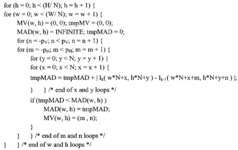
Fig. 1. Motion-estimation algorithm through six nested loops.
with the data-reuse level, with a weaker data-reuse level con-suming less local memory and a stronger data-reuse level quiring more. The relationship among local memory size, re-quired memory bandwidth, and different data-reuse levels is an-alyzed herein. FSBM architecture designers can thus trade-off among these quantitative constraints and make suitable deci-sions.
The existing literature has largely overlooked the classifica-tion of FSBM arrays. [15] presented a classificaclassifica-tion derived from dependency graph (DG) transformation. This classifica-tion divides FSBM arrays into six types, each classified ac-cording to the distribution of the subtraction-absolute-accumu-lation (SAA) operation. However, such a classification reveals few implementation issues. Consequently, a new architectural classification for FSBM array is also proposed herein. The novel classification derives seven types of data-reuse-efficient archi-tectures that are mutually transformable using simple transfor-mation operators “delay and rotate”. Designers can easily iden-tify implementation considerations from the novel classifica-tion. Each type directly identifies the interconnection structure between PEs. The novel classification is based on three data sequence scheduling strategies, each representing an efficient data-reuse scheme. Since data reuse is involved, local memory is established, and the local memory issue can also be easily un-derstood using the novel classification. The accumulation issue and its latency of different types are also addressed herein, and finally, the classified architectures are compared.
A one-access FSBM architecture for high quality video format is proposed herein. One-access indicates that each pixel is accessed just once, as in data reuse Level D and its . The memory bandwidth requirement is minimized when one-access is achieved, successfully overcoming the huge bandwidth problem in ME of high quality video. Features of the proposed design are then discussed.
The rest of this paper is organized as follows. Section II an-alyzes memory accesses and data reuse in ME. Section III then discusses scheduling strategies and presents a classification of data-reuse-efficient ME architectures. To maximize data reuse,
Section IV proposes the one-access architecture. Conclusions are finally drawn in Section V.
II. ANALYSIS OFDATAREUSE ANDMEMORYACCESSES IN MOTIONESTIMATION
A redundancy access factor is defined to evaluate the ef-ficiency of memory accesses used in FSBM
total number of memory accesses in task
pixel count in task (1)
The memory bandwidth of FSBM then becomes
(2) represents the average access count per pixel in FSBM processing, with a smaller value indicating greater reduction of memory bandwidth. When the of an architecture equals one, the architecture is said to be one-access and minimum memory bandwidth is achieved.
The FSBM algorithm can be expressed using C-like lan-guage, as in Fig. 1.
In the above algorithm, and represent the horizontal and vertical search displacement, respectively. Meanwhile,
is the pixel intensity of the current frame and is the pixel intensity of the previous frame.
For one frame ME, as described in Fig. 1, the operation count can range up to
in terms of SAA operation, as indicated in (3). Each SSA operation requires two pixels. A total of
pixels are thus accessed from the frame memory. However, each frame contains only unique pixels. The excessive frame memory access results from each pixel having multiple accesses. Redundancy access is measured using the equation
Consequently, each pixel is accessed an average of
times. These redundant accesses introduce a large memory bandwidth overhead.
A. Locality in Current Frame
In FSBM, each current block is independent, i.e., pixels of one current block do not overlap with other current blocks. Con-sequently, the lifetime of the pixels of the current block is just the time period of motion-estimating one current block. Each pixel in the block is used times during this period, showing that pixels of the current block have good locality com-pared with pixels of the search area. This characteristic allows the simple approach of keeping all current block pixels locally, allowing the design to result in a re-duction in memory accesses of the current frame. Therefore, the additional local memory reduces the access count of the current frame to just for each frame, which is also the maximum possible saving. This idea is widely applied in many proposed ME architectures for minimizing current frame band-width. Consequently, the redundancy access of the current frame is as shown in the equation at the bottom of the page.
B. Locality in Previous Frame
Each search area in the previous frame is a
rectangle centered around related current blocks. Adjacent search areas thus overlap and are no longer indepen-dent. The locality of search area data has two types: local locality and global locality. Local locality covers data reuse within a single search area, regardless of overlapping among other search areas. Global locality covers data reuse among different search areas. Four data-reuse levels are defined according to the degree of data reuse: from Level A (weakest reuse degree) to Level D (strongest reuse degree). The data-reuse level is an important factor in dealing with the memory bandwidth requirements of ME. Because stronger reuse level reduces , i.e., less memory bandwidth is required. Furthermore, in most applications, only can be varied to reduce memory bandwidth, as shown in (2). The four reuse levels are defined below.
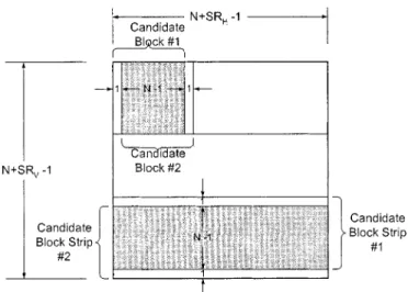
1) Level A—Local Locality Within Candidate Block Strip: Local locality can be further divided into locality within
the same row and locality between adjacent rows. A row of candidate blocks is called a candidate block strip, as shown in upper half of Fig. 2. The extension direction of the candidate block strip is arbitrarily chosen. For the two consequent candidate blocks of two motion vectors (MVs) given, pixels are significantly overlapped. The pixel access count without any data reuse is for calculating the two MVs, but only individual pixels exists. Candidate blocks #1 and #2 in Fig. 2 demonstrates this situation. Consequently, while dealing with candidate block #2, the overlapped data of candidate block #1 can be reused without accessing the frame memory again. The data-reuse approach can be extended to the
Fig. 2. Level A schematic: local locality within candidate block strip. Level B schematic: local locality among adjacent candidate block strips.
entire candidate block strip, i.e., pixels can be repeatedly used for adjacent MV calculations.
2) Level B—Local Locality Among Adjacent Candidate Block Strips: Vertically adjacent candidate block strips also
overlap significantly, as demonstrated by candidate block strips #1 and #2 in the lower half of Fig. 2. The size of the overlapping region of two candidate block strips is . The pixels in the overlapped region can be reused while pro-cessing the next candidate block strip, exploiting the locality of adjacent candidate block strips. This idea is extended to all candidate block strips within the search area.
3) Level C—Global Locality Within Search Area Strip: The
global locality within the search area strip describes data reuse among different search areas corresponding to the location of their current blocks within the same search area strip. The search area strip is like an up-sampled version of the candidate block strip, and is formed by entire rows of search area. The deriva-tion resembles the scheme in Level A, and thus the formula and derivations are ignored herein.
4) Level D: Global Locality Among Adjacent Search Area Strips: Level D resembles Level B, except that it applies to the
search area strips. Level D repeatedly reuses data already loaded from former search area strips for latter search area strips. Ap-plying this level, one-access is achieved.
C. Bandwidth Requirement of Data-Reuse Levels
Equation (2) reveals that required bandwidth is actually de-termined by . The factor for each data-reuse level can be calculated as shown in the equation at the bottom of the next page.
For simplicity, the above calculations assume and . The above four levels provide a good indication of the amount of memory bandwidth required for a given FSBM
TABLE I
BANDWIDTHREQUIREMENTS ANDDATAREUSELEVEL OFVARIOUSVIDEOFORMATS
design. Table I presents the bandwidth requirements for various common video formats corresponding to different data-reuse levels using (2). The required bandwidth easily reaches tens of gigabytes per second for high-quality video with weak data reuse, but falls significantly to sub-gigabytes per second when a higher data-reuse level is adopted. This phenomenon provides a good reason for considering stronger data-reuse level to lower frame memory bandwidth, or using low-cost memory modules or narrow bus width. Wide bus makes the chip package more costly and increases problems with skew. Furthermore, from a systematic point of view, memory traffic introduced by other components such as variable-length-codec, DCT/IDCT, and so on must also be considered. Additionally, the motion-estima-tion process only uses the luminance pixel data, while the other components also use chrominance data thus increasing the im-portance of strong data-reuse level.
All four of the above reuse levels are intra-frame data reuse. There is still another inter-frame reuse level. For example, if we
motion estimate frame , frame serves as the current frame and frame serves as the previous frame. When advancing to frame , frame servers as the current frame and frame becomes the previous frame. No-tably, frame is actually accessed twice, and this reuse can be defined as Level E, the ultimate data-reuse level. However, achieving data reuse Level E involves a significant penalty, i.e., storing at least one frame. Furthermore, bi-directional ME, such as that used in MPEG2, has to store more than one frame, be-cause this data-reuse level predicts across several frames. Level E implementation is impractical, so only Levels A–D are con-sidered herein.
D. Local Memory Size Derivation
To realize data reuse, local memory holding already loaded data for further access is required. The local memory required for the current frame, i.e., for storing one current block is .
Level A (# of candidate block strips) (# of memory access per candidate block strip) Previous Frame Size
Level B (# of search area) (# of access of memory per search area) Previous Frame size
Level C (# of search area strips) (# of memory access per search area strip) Previous Frame Size
Level D (# of memory access of all search area strips) Previous Frame Size
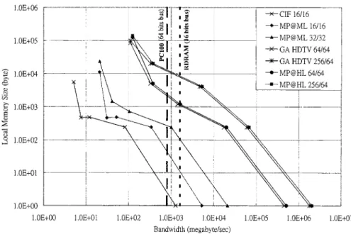
Fig. 3. Relationship between bandwidth requirements and local memory size for various video formats and data-reuse levels.
TABLE II
LOCALMEMORYSIZE FORDIFFERENTREUSELEVELS OFPREVIOUSFRAMES
The local memory size for the previous frame equals the size of the overlapped region in each data-reuse level. Table II lists the derived size, which theoretically should be the upper limit of a novel design. Actually however, few overheads exist for preloading or scheduling data. A properly scheduled data se-quence can eliminate the need for local memory. Section IV discusses the scheduling. Meanwhile, Fig. 3 presents a quanti-tative example of local memory size versus bandwidth require-ments for different video formats. Each curve consists of five data points, with the upper four points representing Levels D (upper most) to A (lower most), while the lowest point repre-sents no data reuse. The numbers labeling the different video formats are the search ranges, . Meanwhile, the two dashed vertical lines, 1.6 GB/s for RDRAM (16-bit bus) and 800 MB/s for PC100 (64-bit bus), indicate the peak bandwidth of current commodity memories [34]. Even the RDRAM scheme was found to be unable to satisfy the Level B and A bandwidth requirements of high-resolution video formats. Meanwhile, the PC100 scheme cannot afford a bi-directional Level C require-ment. The analysis presented in Fig. 3 outlines a good tradeoff decision.
III. CLASSIFICATION OFDATAREUSE-EFFICIENT ME ARCHITECTURES
This section provides a new classification that directly addresses data-reuse efficiency. While many ME architectures have been proposed, few ME classifications have been men-tioned. DG transformation [9], [15], and [28] can serve as a basis for classification through different mapping procedures. [15] proposes a classification for FSBM architectures which is derived from DG transformation and which divides FSBM arrays into six different types. Different arrays of the same type are characterized by the distribution of SAA operations among PEs. However, such classifications reveal little about imple-mentation. Numerous important implementation considerations are easily identified from our classification.
A. Scheduling Strategies
Three scheduling strategies for the array processor are de-rived according to the property of data reuse. The three strategies chosen have an important common property: heavy exploiting of the data reuse of FSBM in the spatial or temporal domains. This property removes redundancies in FSBM and helps to de-velop a data-reuse-efficient architecture. Most novel FSBM ar-chitectures, both 1- and 2-D, are covered by these three sched-uling strategies, which are defined as follows.
Concurrent Mode: This strategy is a data broadcast scheme,
i.e., the same pixel is used simultaneously by multiple PEs. Using the DG projection procedure mentioned in [27], [28] to demonstrate this strategy, the six-loop algorithm in Fig. 1 is
folded into two loops: ,
as shown in Fig. 4. Then, processor basis and scheduling vector are chosen. defines the mapping from DG nodes to PEs and defines the execution order of nodes following the procedure in [27], [28]. From a hardware perspective, defines the number of PEs and defines the PE interconnection and execution order. This projection defines the data-reuse property of current block pixel
Fig. 4. Motion-estimation algorithm folded into two nested loops. The MV calculation is omitted.
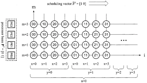
Fig. 5. Concurrent mode example for current block data, with the indexes being simplified from folded loops:N = SR = SR = 4.
Fig. 6. Data sequence example involving three scheduling modes. (a) Concurrent mode. (b) Pipeline mode. (c) Store mode. as the concurrent mode, the data sequence example of
which is displayed in Fig. 5. Owing to the broadcasting scheme of the concurrent mode, local memory and interconnection between PEs is unnecessary, regardless of the local memory size derived in Table II.
Pipeline Mode: The projection parameters for this strategy
are and , and the data-reuse property
of current block pixel is defined as the pipeline mode. Fig. 6(b) illustrates the data sequence example. For this strategy each PE must propagate its currently used data to the
neigh-TABLE III
CLASSIFICATION OFSEVENARRAYTYPES
boring PE at the next cycle, meaning that both interconnection between neighbor PEs and local memory for holding data are required.
Store Mode: The folded algorithm is . With
projection parameters of and , the
data-reuse property of current block pixel is defined as the store mode. Fig. 6(c) shows the data sequence example. In this strategy, data are only saved and used within each PE, meaning that only local memory has to be set up.
Though only the current block data is demonstrated herein, the search area pixels are simultaneously co-scheduled using the three strategies to maximize data reuse. Various co-scheduled data-reuse-efficient architectures are classified below.
B. Classification of Seven Array Types
This classification covers all seven types of efficiently co-scheduled architecture. The folded loops and projection parameters and of each type are described below. While the parameters below are used for 1-D architectures, 2-D architectures can be obtained in a similar fashion. Using these parameters to derive the PE and interconnection structures through DG mapping methodology is a simple matter. The published 1- and 2-D architectures relating to each type are also included, as classified in Table III.
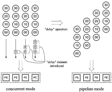
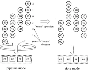
These seven types can be transformed using the transforma-tion operators “delay” and “rotate”. These two operators can convert one scheduling mode to another. The concurrent and pipeline modes are convertible through a delay operation, i.e., inserting delay elements into the data input sequence as illus-trated in Fig. 7. The pipeline and store modes can be converted by a rotation operation as illustrated in Fig. 8. Each row of the input data sequence in Fig. 8 is “left-rotated” according to the rotation distance, with “0” meaning no rotation, “1” meaning
Fig. 7. The “delay” operation.
left-rotate one node position, “2” meaning left-rotate two node positions, and so on.
Owing to the complexity of conversion between the concur-rent mode and the store mode, this conversion is not used herein. Table IV lists the transformations between different types. Ac-tually, these conversions can be obtained via different tradi-tional systolic array mapping methods, but the “delay and
ro-tate” method is easier to understand and is a more intuitive
ap-proach.
C. Comparison of Architectures
Table V lists a theoretical 2-D architecture comparison. These architectures are designed to minimize I/O ports, while main-taining 100% hardware efficiency. The 1-D comparison is not
Fig. 8. The “rotate” operation.
TABLE IV
LIST OFTRANSFORMATIONSBETWEENDIFFERENTTYPES
TABLE V
COMPARISONWITHN = 16; SR = SR = 32
included because it is simpler and less revealing. To allow a fair
comparison, the parameters are
as-sumed. The table derives the theoretical local memory (L.M.), size of the current block (C.B.), size of the search area (S.A.), accumulation type (Acc. Type), cost of the accumulation type (Acc. Cost), and the latency for completing one current block task. The latency excludes the adder and comparator overheads. Four kinds of accumulation structures exist, namely self accu-mulation, propagating accuaccu-mulation, circulating accuaccu-mulation, and parallel accumulation, as shown in Fig. 9, and the actual
Fig. 9. Four kinds of accumulation structure. (a) Self accumulation. (b) Propa-gating accumulation. (c) Circulating accumulation. (d) Parallel accumulation.
accumulation structure can be found in related works. The ac-cumulation cost is the total adder bits of accumulator. Notably, some fields of the local memory size are zero, a phenomenon that is caused by the broadcasting mechanism. From the per-spective of VLSI implementation, the broadcast mechanism will cause significant load capacitance and skew problems. Architec-ture [33] uses a slower data input rate to overcome the problem of current block broadcasting. This approach is possible because the tasks in [33] are interleaving processed by fewer PEs, and thus the required data input rate of the current block is scaled down. But fewer PEs produce less computational power un-less operating frequency is increased. A similar problem occurs when a shared bus is used to carry the final MADs, like the ar-chitectures in [12], [14], [16], [30], and [33]. This problem is solved in [33] by the slower data rate, as mentioned above.
All of the 2-D architectures in Table VI apply data reuse Level C, the data-reuse level achieved by most proposed archi-tectures. Levels A and B are inefficient and cost more I/O pins for 2-D architecture design. Meanwhile, Level D needs more local memory because of the stronger data reuse involved. Con-sequently, the local memory structure and its interface to PEs must be carefully designed. Section IV discusses the Level D architecture design.
IV. ONE-ACCESSARCHITECTURE
This section presents the FSBM architecture design of data reuse Level D, i.e., the one-access architecture. The architecture is of the CPSS type. The proposed architecture mostly comprises a ME core and some on-chip memory. Since it is inefficient to store entire frame in on-chip memory, off-chip memory (such as SDRAM) is also used. Off-chip memory bandwidth in high quality video ME with a large frame size and wide search range is the main barrier in designing a cost-efficient architecture. The proposed architecture eliminates the frame memory bandwidth bottleneck by exploiting the maximum data reuse and successfully reduces bandwidth to a level easily handled by commodity memory. Carefully local memory setup optimizes the local memory size to a near minimum value and few overheads are introduced. Simple and regular interconnections ensure high-speed operation, while efficient and distributed local memory organization is used to provide enough data. Just two I/O ports are required, one for the current block data and the other for the search area, but 100% hardware efficiency is still achieved.
TABLE VI
COMPARISON OF2-D ARCHITECTURES
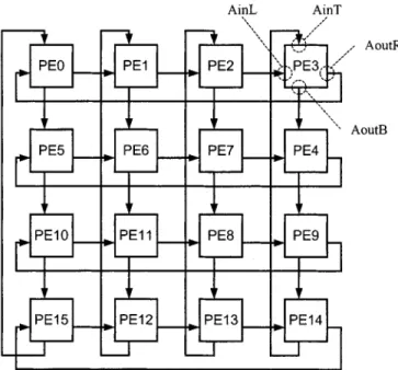
Fig. 10. Overview of the proposed CPSS type architecture and the interconnections of PE ports Pin, Pout, SA, and SUM.
Fig. 11. PE structure.
A. Architecture Overview
The architecture proposed herein is a 2-D design with PEs. For ease of illustration, and were se-lected. Consequently, total of 16 PEs exist, and the search range is 8. Fig. 10 presents an overview of the one-access architec-ture. The overview shows the three top module I/O ports and their connections, and reveals the two data-loading paths of the search area and the current block data. The search area data are loaded into PEs in series using a shared bus, and the current
Fig. 12. Data path of current block data and the interconnections of ports AinT, AoutB, AinL, and AoutR.
block data are loaded in a propagating fashion. The data path of MAD calculation is also displayed, and is a parallel adder tree design. At the output of the final stage of the adder tree, the best MV Finder determines the best motion vector. Notably, the
Fig. 13. Data sequence of the search area pixels.
architecture is illustrated in a 1-D scheme for simplicity; it is actually a 2-D architecture.
Fig. 11 shows the PE structure. Each PE contains one ac-tive register (AR) for holding acac-tive current block data, and one preload register (PR) for propagating the current block data of the next macroblock. The data provided by PRs fill the time gap between successive macroblocks. The multiplexer (MUX) se-lects data from either AR or PR. A search area memory (SAM) stores necessary search area data for data reuse. Finally, an SSA unit (SSAU) calculates the absolute difference between current block and search area data. Eight ports exist per PE, and Figs. 10 and 12 illustrate the interconnections of these ports. Notably, the adder tree is ignored in Fig. 12 for simplicity.
B. ME Operation
The partial MAD calculation (3) is distributed among all PEs in the novel architecture. The SSAU is responsible for calcu-lating the absolute difference between current block pixel and search area pixel, and thus it defines which of the pixels are paired with PEs and how. The search area data are distributed among SAMs. If the search area pixel are labeled ,
where , then will be distributed
to SAM of # % . Consequently, SAMs differ in size, and their size can be calculated according to the pixel distribution just mentioned. Total on-chip SAM size can then be calculated by summing all SAMs. The search area data are static within the SAM and will never be passed to another SAM, making the connection between SSAU and SAM very simple. Fig.13 lists the sequence of the search area data, while Fig. 14 lists the sequence of the corresponding current block data. Ex-amining the data sequence in Fig. 14 and the circulating path in Fig. 12 easily reveals the horizontal and vertical circulation property of the current block.
At the beginning of a macroblock processing, both current block data and search area data must be prepared immediately
to avoid idle cycles. The current block data are pumped in par-allel from PRs into ARs, and the search area data are prepared concurrently from the SAMs. [29] lists further transaction de-tails.
C. Performance and Comparison
The proposed ME architecture is characterized by low memory bandwidth, low latency, minimum I/O port, 100% hardware efficiency, and simple interconnections among PEs. Memory bandwidth is reduced to just twice the luminance bit rate of video sequence by using the data reuse Level D. The memory bandwidth of ME is only influenced by frame rate and frame size, regardless of changes in search range. The low latency delay is due to the parallel loading of both the search area and current block data. The theoretical latency for the
processing of each macroblock is .
For and (a
real video compression case), this architecture can complete each macroblock in just 1024 clock cycles, plus the overhead introduced from the adder tree and MV finder. This architecture has only two I/O ports, one for loading current block data and the other for loading search area data. Avoiding transition gap between macroblocks is essential to 100% utilization. Both current block and search area data should be prepared before next macroblock to avoid transition gap. The current block data are prepared by PRs and the search area data are prepared by SAMs. The data preparation also applies to macroblocks at frame boundaries, thus the one-access architecture is able to be 100% utilized via a suitable data loading sequence. The detailed transitions were provided in reference [29]. The interconnection linking PEs is simple and local.
Tables V and VII compare the proposed architecture and other architectures under different parameters. The comparisons use the HDTV video format
Fig. 14. Data sequence of the current block pixels. TABLE VII
COMPARISONWITHN = 16; SR = SR = 64
of a macroblock increases with the frame size (assuming the same macroblock size), thus enlarging the search range of the high-resolution video. To show the influence of the large search
range, and are used in Table V,
while and are used in Table VII.
The comparisons focus on frame memory bandwidth, input pin count, and hardware utilization; each pixel is assumed to have 8-bit width, and the bandwidth is measured in megabytes per second. Tables V and VII display that the novel architecture maintains the same low memory bandwidth and input pin count when the search range changes, while still achieving 100% hard-ware utilization, making it suitable for high quality video for-mats.
V. CONCLUSION
This work analyzes the I/O bound problem in ME and proposes several methods of reusing data to solve this problem. Different degrees of data reuse are classified into four levels. Greater data reuse requires lower frame memory bandwidth, but uses more local memory. Data reuse Level D achieves
the one-access goal of maximum saving in memory band-width. Local memory sizes are derived according to different data-reuse levels. Three elegant scheduling strategies dedicated to the interface between PEs and local memories are then discussed, and a simple mapping procedure is adopted to map the strategies into the hardware. These selected interface varieties can simplify interconnection networks. Applying the three modes to schedule data sequences of both the previous and current frames results in a classification of seven imple-mentation types, from which the costs of different interface modes can easily be depicted. This classification can serve as a basis for analyzing or evaluating existing ME architectures and makes it easier for new designs. Finally, a one-access FSBM architecture that minimizes bandwidth requirements is proposed. This architecture is characterized by: 1) minimum memory bandwidth requirements; 2) low latency; 3) minimum I/O pin count; 4) 100% hardware efficiency; and 5) simple and regular interconnections, features that make it suitable for high quality video ME. The low memory bandwidth also benefits from lower power consumption due to fewer bus transition activities and the adoption of inexpensive frame memory modules. Besides, other modules can obtain more bandwidth owing to memory bandwidth relief from ME in a complete video compression system.
REFERENCES
[1] K. R. Rao and J. J. Hwang, Techniques and Standards for Image, Video
and Audio Coding. Englewood Cliffs, NJ: Prentice-Hall, 1996. [2] J. R. Jain and A. K. Jain, “Displacement measurement and its application
in interframe image coding,” IEEE Trans. Commun., vol. COM-29, pp. 1799–1808, Dec. 1981.
[3] T. Koga et al., “Motion compensated interframe coding for video con-ferencing,” in Proc. Nat. Telecommun. Conf., New Orleans, LA, Nov. 1981, pp. G5.3.1–G5.3.5.
[4] L. D. Vos, “VLSI architecture for the hierarchical block matching algo-rithm for HDTV applications,” SPIE/VCP, vol. 1360, pp. 398–409, Nov. 1990.
[5] B. M. Wang, “An efficient VLSI architecture of hierarchical block matching algorithm in HDTV applications,” in Int. Workshop on HDTV, Oct. 1993.
[6] B. M. Wang, J. C. Yen, and S. Chang, “Zero waiting cycle hierarchical block matching algorithm and its array architectures,” IEEE Trans.
Cir-cuits Syst. Video Technol., vol. 4, pp. 18–28, Feb. 1994.
[7] R. Srinivasan and K. R. Rao, “Predictive coding based on efficient mo-tion estimamo-tion,” IEEE Trans. Commun., vol. COM-33, pp. 888–896, Aug. 1985.
[8] L. De Vos and M. Stegherr, “Parameterizable VLSI architectures for the full-search block-matching algorithm,” IEEE Trans. Circuits Syst., vol. 36, pp. 1309–1316, Oct. 1989.
[9] T. Komarek and P. Pirsch, “Array architectures for block matching algo-rithms,” IEEE Trans. Circuits Syst., vol. 36, pp. 1302–1308, Oct. 1989. [10] C.-H. Hsieh and T.-P. Lin, “VLSI architecture for block-matching mo-tion estimamo-tion algorithm,” IEEE Trans. Circuits Syst. Video Technol., vol. 2, pp. 169–175, June 1992.
[11] H. Yeo and Y. H. Hu, “A novel modular systolic array architecture for full-search block matching motion estimation,” IEEE Trans. Circuits
Syst. Video Technol., vol. 5, pp. 407–416, Oct. 1995.
[12] Y.-K. Lai et al., “A novel scaleable architecture with memory inter-leaving organization for full search block-matching algorithm,” Proc.
1997 IEEE Int. Symp. Circuits and Systems, pp. 1229–1232, June 1997.
[13] Y.-S. Jehng et al., “An efficient and simple VLSI tree architecture for motion estimation algorithms,” IEEE Trans. Signal Processing, vol. 41, pp. 889–900, Feb. 1993.
[14] K.-M. Yang et al., “A family of VLSI designs for the motion compensa-tion block-matching algorithm,” IEEE Trans. Circuits Syst., vol. 36, pp. 1317–1325, Oct. 1989.
[15] S. Chang et al., “Scaleable array architecture design for full search block matching,” IEEE Trans. Circuits Syst. Video Technol., vol. 5, pp. 332–343, Aug. 1995.
[16] S. Dutta and W. Wolf, “A flexible parallel architecture adapted to block-matching motion-estimation algorithms,” IEEE Trans. Circuits
Syst. Video Technol., vol. 6, pp. 74–86, Feb. 1996.
[17] G. Gupta and C. Chakrabarti, “Architectures for hierarchical and other block matching algorithms,” IEEE Trans. Circuits Syst. Video Technol., vol. 5, pp. 477–489, Dec. 1995.
[18] E. Iwata and T. Yamazaki, “An LSI architecture for block-matching mo-tion estimamo-tion algorithm considering chrominance signal,” VLSI Signal
Processing VIII, pp. 421–430, 1995.
[19] B. Liu and A. Zaccarin, “New fast algorithms for the estimation of block motion vectors,” IEEE Trans. Circuits Syst. Video Technol., vol. 3, pp. 148–157, Apr. 1993.
[20] M.-C. Lu and C.-Y. Lee, “Semi-systolic array based motion estimation processor design,” IEEE Proc. 1997 Int. Symp. Circuits and Systems, pp. 3299–3302, 1995.
[21] V.-G. Moshnyaga and K. Tamaru, “A memory efficient array architec-ture for full-search block matching algorithm,” 1997 Proc. IEEE Int.
Symp. Circuits and Systems, pp. 4109–4112, 1997.
[22] S.-H. Nam and M.-K. Lee, “Flexible VLSI architecture of motion esti-mator for video image compression,” IEEE Trans. Circuits Syst. II, vol. 43, pp. 467–470, June 1996.
[23] B. Natarajan et al., “Low-complexity algorithm and architecture for block-based motion estimation via one-bit transforms,” IEEE Trans.
Circuits Syst. Video Technol., vol. 6, pp. 3244–3247, 1995.
[24] P. A. Ruetz et al., “A high-performance full-motion video compression chip set,” IEEE Trans. Circuits Syst. Video Technol., vol. 2, pp. 111–122, June 1992.
[25] C. Sanz et al., “VLSI architecture for motion estimation using the block-matching algorithm,” in Proc. Eur. Design and Test Conf., 1996, pp. 310–314.
[26] C.-L. Wang et al., “A high-throughput, flexible VLSI architecture for motion estimation,” 1995 Proc. IEEE Int. Symp. Circuits and Systems, pp. 3289–3295, 1995.
[27] S. Y. Kung, VLSI Array Processors. Englewood Cliffs, NJ: Prentice-Hall, 1988.
[28] Y.-K. Chen and S. Y. Kung, “A systolic design methodology with appli-cation to full-search block-matching architectures,” J. VLSI Signal
Pro-cessing, pp. 51–77, 1998.
[29] J.-C. Tuan and C.-W. Jen, “An architecture of full-search block matching for minimum memory bandwidth requirement,” in Proc. IEEE 8th Great
Lake Symp. VLSI, 1998, pp. 152–156.
[30] Y.-K. Lai and L.-G. Chen, “A flexible data-interlacing architecture for full-search block-matching algorithm,” in IEEE Int. Conf.
Application-Specific Systems, Architectures and Processors, 1997, pp. 96–104.
[31] H.-D. Lin et al., “A 14-Gops programmable motion estimator for H.26X video coding,” IEEE J. Solid-State Circuits, vol. 31, pp. 1742–1750, Nov. 1996.
[32] S. B. Pan et al., “VLSI architectures for block matching algorithms using systolic arrays,” IEEE Trans. Circuits Syst. Video Technol., vol. 6, pp. 67–73, Feb. 1996.
[33] J. You and S. U. Lee, “High throughput, scalable VLSI architecture for block matching motion estimation,” J. VLSI Signal Processing, vol. 19, pp. 39–50, 1998.
[34] Next-Generation DRAM Comparison (1999). [Online]. Available: http://www.micron.com
Jen-Chieh Tuan received the B.S. degree in electrical engineering from National Tsing Hua University in 1995 and the M.S. degree in electronics engineering from National Chiao Tung University, Hsinchu, Taiwan, R.O.C., in 1997.
He is currently a Logic Design Engineer of iCreate Technologies Corporation, Hsinchu, Taiwan, R.O.C.
Tian-Sheuan Chang (S’93–M’00) received the B.S., M.S., and Ph.D. degrees in electronics en-gineering from National Chiao Tung University, Hsinchu, Taiwan, R.O.C., in 1993, 1995, and 1999, respectively.
He is currently a Principle Engineer at Global Unichip Corporation, Hsinchu, Taiwan, R.O.C. His research interests include VLSI design, digital signal processing, and computer architecture.
Chein-Wei Jen received the B.S. degree from National Chiao Tung University, Hsinchu, Taiwan, R.O.C., in 1970, the M.S. degree from Stanford University, Stanford, CA, in 1977, and the Ph.D. degree from National Chiao Tung University in 1983.
He is currently with the Department of Electronics Engineering and the Institute of Electronics, Na-tional Chiao Tung University, as a Professor. During 1985–1986, he was with the University of Southern California, Los Angeles, as a Visiting Researcher. His current research interests include VLSI design, digital signal processing, processor architecture, and design automation. He has held six patents and published over 40 journal papers and 90 conference papers in these areas.